Corrugated Tabs for Supersonic Jet Control
←
→
Page content transcription
If your browser does not render page correctly, please read the page content below
Corrugated Tabs for Supersonic Jet Control
                                                  (Keynote Paper)

                                                  Rathakrishnan E*

ABSTRACT

The efficiency of corrugated tabs in promoting the mixing of Mach 1.8 axi-symmetric free jet has been investigated
experimentally. Two rectangular tabs of 4.2% blockage, with corrugations at the edges, located diametrically
opposite at the exit of a Mach 1.8 convergent-divergent nozzle were found to be better mixing promoters than
identical rectangular tabs without corrugations, at overexpanded, correctly expanded and underexpanded states of
the jet. Furthermore, the corrugated tabs were found to be more efficient in weakening the shocks in jet core
compared to the plain tabs. As high as 78% of reduction in core length was achieved with corrugated tabs for the jet
operated at nozzle pressure ratio (NPR) of 7, the corresponding reduction with the plain tabs is only 54%. The
mixing effectiveness of corrugated tabs increases progressively with increase of NPR whereas, the maximum mixing
effectiveness of the plain tabs is found to be at the correctly expanded state. Shadowgraph pictures of the
uncontrolled and controlled jets clearly demonstrate the effectiveness of corrugated tabs in weakening the waves in
the jet core. The speculation of smaller vortices generated by the corrugated tab is supported by a preliminary
visualization with water flow channel.

INTRODUCTION

      Control of high speed jets with passive control in the form of tabs of various shapes has been
reported by large number of researchers in open literature. The generation mechanism of the streamwise
vortex pairs by tabs and their effect on entrainment and spreading of free jets have been discussed in
literature [1, 2, 3]. In the studies reported so far, tabs of straight edges only have been studied. Recently, it
has been demonstrated that the vortex generated by the flat plate can be manipulated to become smaller
by giving a curvature to the plate (Takama [4]). Exploiting this effect, Thanigaiarasu et al [5] studied arc-
tabs for jet control. To exploit the advantage of smaller vortices, rectangular tabs with corrugated edges
have been studied in the present investigation. Preliminary water flow visualization has also been carried
out to demonstrate that the vortices generated by the corrugated tab are smaller than those shed by the
plain tab.
      Bradbury and Khadem [6] reported the effect of tabs in a low-speed jet. Ahuja and Brown [1] found
that, for a round jet flow of Mach number 1.12 and total temperature 664 K, the potential core length of
the jet could be reduced from about six diameters to less than two diameters by using two diametrically
opposed mechanical tabs. Zaman et al [7] proposed that the distortion introduced by a mechanical tab is
due to a pair of streamwise vortices and which must be responsible for the phenomenal entrainment.
Subsequent researchers (Bohl and Foss [2], Wishart et al [8], Zaman et al [3]) have clearly determined
that the tab produces a pair of counter-rotating streamwise vortices. The relative magnitude of the peak
streamwise vorticity was found to be about 20% of that of the peak azimuthal vorticity for a tabbed
circular jet at a Mach number of 0.3 (Zaman [7]). Zaman [7] and Zaman et al [3] surmised two possible
sources of streamwise vorticity for the flow over a tab (Bohl and Foss [2]). In addition to the pressure
gradients which flux streamwise vorticity into the flow, the well known ‘necklace’ or ‘horseshoe’ vortices
due to boundary layer reorientation can also be important in the flow over a tab. It should be noted that,
*
    Department of Aerospace Engineering, Indian Institute of Technology Kanpur, India; e-mail: erath@iitk.ac.in
the sense of rotation of the vortex pair from the pressure hill is always opposite to that of the necklace
vortex pair.
Several other observations regarding optimal tab placement and shape have been made. Reeder and
Samimy [9] found that the tab is best placed at the trailing edge. In a chemically reacting, compressible,
two-stream shear layer, Urban et al [10] observed a significant increase in product formation and
thickening of the shear layer when a tab with a height of only 5% of the boundary layer displacement
thickness was placed at the trailing edge. After brief parametric studies, both Zaman et al [3] and Urban et
al [10] found the optimal tab shape to be triangular. In the usage of Zaman et al [3], the base of the tab
was attached to the exit edge of a nozzle and the apex tilted downstream. Navin Kumar Singh and
Rathakrishnan [11] investigated on the findings of Zaman et al [7] that for the same projected area, width
of the tab is more effective in enhancing the mixing than its length. But they found that, for the same
projected area, length of the tabs is more effective in enhancing the mixing than its width. In addition to
the influence of tab geometry on mixing, they had postulated that, when the streamwise vortices are
introduced right up to the jet centerline, it may prove to be an advantage in enhancing the mixing as high
as 80%. Further work was done by Sreejith and Rathakrishnan [12] based on the above postulation.
Instead of tabs, a wire running across a diameter (cross-wire) was used as a passive control to enhance the
jet mixing. The streamwise vortices introduced by the cross-wire lead to a more rapid decay of the
centerline pitot pressure. Also, the cross-wire was found to weaken the shocks in the jet core significantly.
The authors had authentically proved that the limit for tab length is the nozzle exit radius and not the
boundary layer thickness. This limit of tab length is termed Rathakrishnan limit (Lovaraju et al [13],
Mrinal et al [14]). Most of the studies cited so far were on free jets discharging into quiescent
surroundings. Ahuja [15] and Carletti et al [16] investigated the effect of tabs for a circular jet with a
cylindrical ejector surrounding the jet. Both found an increased mixing within the ejector under the
influence of the tabs. There have also been a few numerical studies (Grosch et al [17], Steffen et al [18]).
Steffen et al [18] compared numerical results with corresponding experimental results and noted good
agreement in terms of the vorticity field as well as overall jet entrainment. These results lent further
credence to the postulations made on the basic flow dynamics as discussed above. Thus, it is evident from
the above discussions that manipulation of the size of the vortices shed by the tabs play a dominant role in
promoting the mixing of free jets. Also, it is well known that smaller the size the better its mixing
efficiency. With this in mind, corrugations were provided at the edges of rectangular tab with the
intension to making the tabs to shed smaller vortices, compared to an identical tab without corrugation.
The effect of these vortices of reduced size on the mixing enhancement of Mach 1.8 free jet flow has been
demonstrated.
EXPERIMENTAL SETUP AND PROCEDURE
The experiments were conducted in the open jet facility at the High Speed Aerodynamics Laboratory,
Indian Institute of Technology Kanpur, India. The test facility consists of air supply system (which
consists of compressor and storage tanks) and an open jet test facility. The details of the facility are given
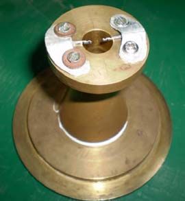
in reference 13. The experimental model used in the present investigation is Mach 1.8 axi-symmetric
convergent-divergent nozzle made of brass. The exit diameter of nozzle is 13 mm. The tabs were made of
1 mm thick aluminum sheet. Two plain rectangular tabs of length 4 mm and width 0.7 mm offering a
blockage of 4.2 percent and two rectangular tabs of identical blockage with corrugation, shown in Figs. 1
and 2, were used in the present investigation. These tabs were located diametrically opposite at the nozzle
exit, as shown in Fig. 1. The centerline pitot pressure distribution, the pitot pressure variation along the
tab direction and normal to the tab direction for the controlled jet and along the radial direction for
uncontrolled jet were measured for nozzle pressure ratios 4, 5, 5.74, 6, 7 and 8, covering the
overexpanded, correctly expanded and underexpanded states for the Mach 1.8 jet. In all the three
directions, the pitot pressures were measured at intervals of 1 mm. The waves prevailing in the supersonic
2jet core were visualized using a shadowgraph system with a helium spark arc light source in conjunction
with a concave mirror. The shadowgraph images were recorded using a still camera.
A water flow channel was used to demonstrate that the vortices shed from the corrugated rectangular
tab are smaller than those shed from the plain rectangular tab. A water flow channel of test-section width
300 mm and water stream depth 5 mm was used for this visualization. For this visualization, the tabs used
were different from those used in the jet study. Two rectangular tabs of 1 mm thickness and identical
blockage, one without corrugation and other with corrugation were made for this visualization. These tabs
were placed in the water flow channel test-section which has been tested for uniform flow by using a dye.
When there is no model, the dye streaks exhibit a fairly uniform pattern in the test-section. The tabs were
placed in the test-section at a Reynolds number of 2238 (based on tab width) and the flow field around the
tab and the wake behind the tab were recorded using a video camera. Image of the required portion of
flow field was extracted from the video.
RESULTS AND DISCUSSION
Centerline Pitot Pressure Decay
The centerline pitot pressure decay is an authentic measure of jet propagation (Lovaraju and
Rathakrishnan [20]) that is, faster the decay, the faster is the jet mixing with the entrained fluid mass and
so on. The centerline pressure decay can clearly show the extent of jet core, which is defined as the axial
extent up to which the nozzle exit velocity prevails for subsonic jets and the axial extent up to which
supersonic flow prevails for supersonic jets. In other words, it can be stated that the core of a jet, either
subsonic or supersonic, is the distance from nozzle exit at which the characteristic decay begins.
The centerline pitot pressure decay for the uncontrolled jet, controlled jet with plain tabs and
corrugated tabs are given in Fig. 3. At NPR 4, Mach 1.8 jet is overexpanded with overexpansion ratio
/ = 0.696. For this level of expansion, there will be an oblique shock at the nozzle exit to increase the
stream pressure to come to equilibrium with the backpressure, which is the pressure of the atmosphere to
which the jet is discharged. The oblique shock from the opposite edges of nozzle exit would cross each
other at a distance downstream of nozzle exit. For the present case of axi-symmetric nozzle, this shock
cross-over point would be at the jet axis. After crossing over, the oblique shocks would get reflected from
barrel shock as expansion waves, since, reflection from a free boundary is unlike (opposite in nature).
These expansion waves would travel up to the opposite boundary of the jet and get reflected as
compression waves and these waves travel from one boundary to another boundary and reflect as
expansion waves. Thus, there are a large number of compression and expansion waves prevailing in the
near field of the jet, where the flow Mach number is supersonic. It is essential to realize that, the flow
Mach number downstream of the oblique shocks at the nozzle exit would be supersonic, but with a
magnitude less than the Mach number upstream of the shock. This is because all the naturally occurring
oblique shocks are weak shocks (Rathakrishnan [19]). Thus, along the jet axis, the flow passes through a
number of compression waves cross-over points and expansion waves cross-over points. As seen in Fig.
3, for the uncontrolled jet, the pitot pressure decreases over a very narrow range of X/D from 0 to about
0.5. This is because, at the exit of the nozzle, there is an oblique shock caused by overexpansion and an
expansion fan caused by the relaxation effect due to the larger space available for the flow to expand soon
after exiting the nozzle (Rathakrishnan [21]). Therefore, the combined effect of the compression caused
by the oblique shock and the expansion caused by relaxation, dictates the flow Mach number. From X/D
= 0 to about 0.5, the pitot pressure decrease indicates acceleration of the flow. The pitot pressure attains a
minimum at X/D = 0.5. This should be the location just upstream of shock cross-over point. Soon after
the flow experiences deceleration due to the combined effect of two compression waves crossing. The
flow behind the cross-over point essentially becomes subsonic. The subsonic flow acceleration
downstream of the shocks cross-over point is indicated by the increase of pitot pressure from X/D = 0.5
onwards. At about X/D = 1, the flow attains transonic level, followed by further acceleration to
3supersonic Mach numbers. The first pressure maximum peak is a location of transonic Mach number. It is
important to note that the subsonic flow downstream of shock cross-over point accelerates to higher Mach
numbers by gaining momentum from the higher momentum fluid mass around the jet axis, where the flow
was traversed by only one compression wave. After attaining the transonic Mach number, the flow
encounters acceleration due to momentum gain as well as because of being traversed by expansion waves,
which are the reflections of compression waves from the jet boundary. The accelerating flow attains a
maximum Mach number at the location, where the pitot pressure shows a minimum peak at X/D slightly
less than 2. Downstream of this minimum pressure point, the subsonic flow accelerates, attains transonic
Mach number and continues to accelerate to attain a third supersonic Mach number maximum, which is at
about X/D = 3.2. This cycle of acceleration continues exhibiting wavy nature of pitot pressure up to about
X/D = 8.4. Beyond that, there is continuous decrease of pitot pressure indicating the jet undergoing
characteristic decay. Beyond X/D about 14, the pitot pressure asymptotically approaches fully developed
region. Thus, for the uncontrolled jet, the supersonic core (axial extent up to which wavy nature of
supersonic flow prevails) extends to about X/D = 8.4. From X/D = 8.4 to 14, the flow exhibits
characteristic decay and X/D beyond 14 could be taken as the fully developed zone of the jet. The
distance between one minimum peak to another minimum peak can be taken as a shock cell length
(Lovaraju and Rathakrishnan [20]). Thus, there are about six shock cells for the uncontrolled jet at NPR 4,
also the shocks in the jet core are of considerable strength. When the plain tab is placed at the nozzle exit,
as expected, the waves in the jet core become weaker, also the core length comes down from X/D = 8.4
for the uncontrolled jet to about X/D = 6.4 for the jet with plain tabs, and to about X/D = 6 for corrugated
tabs of same blockage of 4.2% as the plain tab. At NPR 4, both plain and corrugated tabs influence the jet
mixing significantly, making the waves in the jet core to become weaker compared to the uncontrolled jet.
For the correctly expanded jet at NPR 5.74, as seen in Fig. 4, the core length decreases from about
10D to 4D for the plain tabs and 3D for the corrugated tabs. That is, core length reduction of about 70%
is achieved with the corrugated tabs. That is, even in the presence of zero pressure gradient at the nozzle
exit, the corrugated tabs could be able to promote mixing to a greater extent than the plain tabs. That is,
even at zero pressure gradient the mixing efficiency of the corrugated tabs is much superior than the plain
tabs which cause a core length reduction of only about 60%. The characteristic decay for the corrugated
tabs is found to be faster than the plain tabs, but in the flow field beyond X/D = 14, both the tabs
influence the field almost identically.
At NPR 6, with a marginal favorable pressure gradient at the nozzle exit, the core length for
uncontrolled jet extends up to about 11.4D, whereas for the plain tabs the core length comes down to
about 9.2D and for the corrugated tabs the core length comes down to 8.4D. That is, the plain tabs reduce
the core length to about 19% and the corrugated tabs reduce the core length to about 26%. Also, the
waves in the first three shock cells are weaker for the corrugated tabs than the plain tabs.
At NPR 7, the waves in the core of the uncontrolled jet become very strong and the core extends as
long as about 20D. For the plain tabs, the core comes down to about 9.2D. Also, the waves in the core
beyond the first shock cell are made significantly weaker. The corrugated tabs result in a drastic reduction
of jet core to about 4.4D. This is about 78% decrease in core length is achieved with corrugated tabs.
Another interesting fact is that the shocks in the core, including the first cell are made considerably
weaker by the corrugated tabs. The difference in the area enclosed by pitot pressure curves of
uncontrolled and controlled jets is larger for the corrugated tabs, indicating the mixing caused by
corrugated tabs is much larger than the plain tabs. For this case, the jets with tabs show their individual
identity up to about 18D.
At the largest tested NPR of 8, the favorable pressure gradient is / = 1.392. The results show that
the core length is about 13.6D for uncontrolled jet, 12.8D for the plain tabs and 11.2D for corrugated tabs.
Even though, the core length reduction achieved with corrugated tabs is not significant, the corrugated
tabs cause the waves in the jet core to become weaker compared to the plain jet. Though acoustic
measurements are not made in the present investigation, weakening the waves in jet core can be taken as
an advantage from noise reduction point of view (Verma and Rathakrishnan [22]).
4From the above discussions of centerline pressure decay of uncontrolled and controlled jets, it is
evident that the effectiveness of tabs is strongly dictated by the level of expansion at the nozzle exit. An
interesting feature found is that, unlike the literature information namely, the control effectiveness
increases with increase of favorable pressure gradient, the tabs are found to be most efficient at and
around correctly expanded condition. This kind of observation was also reported by Navin Kumar Singh
and Rathakrishnan [11] for the limiting case of the tab length namely, a tab running across the diameter of
the nozzle exit, named cross-wire. Therefore, it is essential to relook into the statement that the control
effectiveness increases with increase of favorable pressure gradient as report in the literature.
The core length reduction achieved with the plain tabs and corrugated tabs are calculated for all the NPRs.
The Percentage reduction in core length is defined as,
and the effectiveness of corrugated tabs over plain tabs is defined as,
–
where, ΔL is reduction in core length.
The core length, core length reduction and the effectiveness of corrugated tabs over plain tabs at
different NPRs are tabulated in Table 1. It is seen that, in the presence of adverse pressure gradient, zero
pressure gradient as well as favorable pressure gradient, the corrugated tabs are more efficient in mixing
promotion than the plain tabs. However, the effectiveness of corrugated tabs is strongly influenced by the
level of expansion. Thus, it can be summarized that, generation of smaller vortices by the corrugated tabs,
compared to uniform size vortices shed by the plain tabs, is more efficient in promoting mixing, in
accordance with the vortex dynamics that, smaller the vortex size the better is the mixing efficiency.
Pressure Profiles
The pitot pressure ( ) distribution, measured along the tabs and normal to the tabs directions for the
controlled jets and along the radial direction for uncontrolled jet are made non-dimensional by dividing
with the settling chamber pressure ( ). The radial (R), transverse (Y) i.e. along the tab and normal (Z)
i.e. normal to the tab are made non-dimensional by dividing them with nozzle exit diameter (D).
The pitot pressure profiles for the uncontrolled jet at axial distances of X/D = 0.5, 1, 2, 4, 6 and 10 are
presented in Fig. 5a, for NPR 4. At X/D = 0.5, it is seen that, at the jet axis the pitot pressure is the
minimum. This implies that the jet velocity is maximum at that point. Away from the jet axis, the pitot
pressure shows almost constant level up to about R/D = 0.5, followed by a steep decrease from 0.5 to 0.6.
Beyond R/D = 0.6, the pitot pressure remains almost a constant with a magnitude of / = 0.25. At X/D
= 1, around the jet axis, the pitot pressure exhibits almost a constant pressure zone. This implies that,
there is an uniform Mach number zone around the jet axis. This prevails from R/D = 0 to about 0.3. For
R/D greater than 0.3, the pitot pressure decreases sharply up to about R/D = 0.6. Beyond that, the pressure
remains almost the same. At X/D = 2, the constant pitot pressure magnitude around the jet axis is higher
than X/D = 1. But, the radial extent of this peak pressure is from R/D = 0 to about 0.25 only. At X/D = 4,
the pitot pressure peak value comes down to 0.8 and also the decrease of pressure shows relatively a
gradual variation than the near field profiles upstream of this location. At X/D = 6, there is no constant
pressure zone around the jet axis, as exhibited by the single peak pitot pressure profile. Also, in the radial
direction the pressure decreases gradually, attaining a minimum pressure level of / = 0.2 at R/D =
around 1. At X/D = 10, the jet has encountered the characteristic decay and the pitot pressure decay
shows almost fully developed nature. In all these profiles, it is interesting to note that, the pressure
5profiles are not symmetric about the jet axis. This is because, the jet field is essentially vortex dominated
and hence, due to the vortex action, the field is rendered asymmetric, even though the jet at X/D = 0 is
essentially axi-symmetric.
For the controlled jet with plain tabs, the pitot pressure along and normal to the tabs are shown in
Figs. 5b and 5c. It is seen that, the y-profile at X/D = 0.5, does not exhibit any dip as in the case of
uncontrolled jet. Further, there is a constant pressure zone around the jet axis. This is a clear indication of
the mixing caused by the vortices shed from the tabs right at the nozzle exit. Further, the fall after the
peak pressure is also slightly reduced compared to the uncontrolled jet. The jet is rendered more
asymmetrical compared to the uncontrolled jet. Another interesting feature is that, the pressure profiles at
X/D = 1, 2 and 4 are with marginal variation in the peak pressure around the jet axis. This is a clear
indication of momentum transport caused by the control tabs. At X/D = 6, the peak pressure is much
higher than the uncontrolled jet. This is because the shock cells are made weaker by the tabs, as seen in
the centerline pressure decay plots. Due to these weakened waves, the flow could able to retain its
pressure level to a longer distance compared to the uncontrolled jet. Due to similar reason, at X/D = 10
also the peak pressure is greatly larger than the uncontrolled jet. However, in the far field the pressure
levels are almost comparable to the uncontrolled jet. This feature was observed as almost similar
asymptotic decay of controlled and uncontrolled jets in the far field from the centerline pitot pressure
decay results. The z-profiles are distinctly different from the y-profiles. This is a clear indication of the
asymmetry to the jet propagation introduced by the tabs. In z-profiles, the peak profile zone is narrower at
all axial distances compared to the y-profiles. This is because, in the direction normal to the tabs, the flow
could able to spread greatly without the influence of the vortices shed by the tabs. In other words, unlike
the direction along the tab, normal to the tab the flow could able to relax better because of the absence of
any solid body. In the z-profiles, at about X/D = 2, 4 and 6, the profiles exhibit off-center peaks. This
shows that, slightly downstream of the tabs, the jet is essentially bifurcated exhibiting two high-velocity
zones on either side of the jet axis. But at X/D = 10, the z-pressure profile is almost identical to the y-
profile. In the far field, z-profiles are identically the same as the y-profiles and radial profiles of the
uncontrolled jet.
Optical Flow Visualization
At NPR 4, which is an overexpanded state for Mach 1.8 jet, the oblique shocks at the nozzle exit are
clearly seen (Fig. 6). These oblique shocks cross each other at the jet axis and reach the barrel shock. On
reaching the barrel shock, the oblique shock reflects as expansion fan, since reflection from fluid
boundary is unlike (Rathakrishnan [19]). The kink formed at the shock reflection points are clearly seen
in this picture. The expansion waves cross each other and reach the boundary and reflect back as
compression waves. The reflected compression waves once again cross each other at the jet axis and
reflect back as expansion fan from the barrel shock boundary. This kind of wave reflection continues up
to some downstream distance. The distance between the successive shock reflection points (kinks) is
termed shock cell. At NPR 4, four cells are seen in the uncontrolled jet field. The first two cells are
prominent and the third and fourth are weaker.
For the controlled jets with plain and corrugated tabs, the visualization pictures in the direction
normal to the tabs are shown in Fig. 7a, for NPR 4. It is interesting to see that, the shock cells prevailing
in the uncontrolled jet are greatly disturbed resulting in a number of smaller diamond like structures for
both plain and corrugated tabs. However, as it can be seen in Fig. 7a, the first diamond for the plain tabs
is larger. But the second diamond for the corrugated tabs is larger than that of the plain tabs and it
alternates. This kind of number of wave crossings is seen up to some downstream distance for both the
tabs. There are four prominent diamonds along the centerline for the plain tabs. But, for the corrugated
tabs only three such diamonds are prominent. The visualization pictures in the direction along the tabs are
shown in Fig. 7b. Compared to normal to the tabs, along the tabs, the wave pattern is completely
different. Furthermore, the waves in the plain tabs case are relatively stronger than the corrugated tabs.
6At NPR 5.74, it is interesting to note that even at this correctly expanded condition, the jet field is
wave dominated. This is because, as explained by Rathakrishnan [21], the jet encounters an expansion fan
due to the relaxation effect. These expansion waves get reflected as compression waves and the process
continues. For the uncontrolled jet at this NPR also, two prominent shock cells are visible.
For correctly expanded controlled jet operated at NPR 5.74 also there are waves in the jet core due to
the relaxation effect. For the plain tabs, in the direction normal to the tabs, the waves are seen up to a
considerable distance downstream of the nozzle exit. This may be because the expansion at the exit is not
strong, as it is only due to the relaxation effect. Due to this, the flow Mach number changes caused by the
waves are not drastic. Owing to this, supersonic nature of jet could able to prevail over a longer distance
compared to NPR 4, which is an overexpanded operation. Along the tabs also, the shock cells prevail over
longer distance compared to NPR 4.
Water Flow Visualization
It was found that, the corrugated tab causes better mixing than the plain tab. The physical reason for
this was speculated as the vortices shed from the corrugated tab were relatively smaller than those shed by
the plain tab. To authenticate this speculation, a modest experimental visualization with water stream as
the flow medium was conducted. Flow past identical (same blockage) rectangular tabs, one with
corrugation and one without corrugation were visualized. The plain and corrugated tabs were placed in
the test-section with a water stream speed of 20 cm/s. By injecting water color dye, the flow fields behind
the plain and corrugated tabs were visualized. Two pictures of the flow field around the plain and
corrugated tabs are given in Figs. 8a and 8b. It is seen that, in the wake of the corrugated tab the vortices
are smaller, thus causing a better mixing compared to the plain tab. Furthermore, the flow deviation
caused by the plain tab is found to be much larger than the corrugated tab. It is important to note that,
these results are only qualitative in nature. Also, the Reynolds number of water stream, based on the
width of the tab, is just 2238. However, the corrugated tab shedding smaller vortices can be taken as a
supportive evidence of speculation used in the discussion of results of centerline pitot pressure decay and
pitot pressure profiles of jets controlled with plain rectangular and corrugated rectangular tab.
CONCLUSIONS
The quantitative and qualitative results of the present investigation clearly demonstrate that,
1. The corrugated rectangular tabs are better mixing promoters than identical plain rectangular tabs.
2. As high as 78% of reduction in core length is achieved with corrugated tabs for Mach 1.8 jet
operated at NPR 7, which is 24% higher than the core length reduction achieved with plain tabs at
the same operating condition.
3. The mixing promoting efficiency of corrugated tab progressively increases with increase of NPR,
whereas, the maximum efficiency of plain tab is at correctly expanded state. In other words, the
mixing efficiency of corrugated tab is appreciable at all levels of expansion, but for the plain tab,
the mixing efficiency is the highest only at the correctly expanded state. It may also be stated that,
corrugated tab is equally efficient in the presence of adverse, zero and favorable pressure gradients,
whereas the plain tab is not.
4. The shock strength reduction caused by the corrugated tabs is found to be much higher than those
caused by the plain tabs.
5. The mixing promoting small scale vortices generated by the corrugations are found to be
responsible for the increased mixing efficiency of the corrugated tab.
7REFERENCES
[1] Ahuja. K.K, and Brown. W.H. (1989) “Shear Flow Control by Mechanical Tabs”, AIAA Paper 89-
0994.
[2] Bohl. D, and Foss. J.F. (1996) “Enhancement of Passive Mixing Tabs by the Addition of Secondary
Tabs”, AIAA Paper 96-054.
[3] Zaman. K.B.M.Q, Reeder. M.F, and Samimy. M. (1994) “Control of an Axisymmetric Jet Using
Vortex Generators”, Physics of Fluids, Vol. 6, pp. 778-793.
[4] Takama Y, Suzuki K and Rathakrishnan. E (2008) “Visualization and size measurement of Vortex
shed by flat and arc plates in an uniform flow”, International Review of Aerospace Engineering
(IREASE), Vol. 1, No. 1, February 2008, pp. 55-60.
[5] Thanigaiarasu S, Jayaprakash S, Elangovan S and Rathakrishnan E. (2008) “ Influence of tab
geometry and its orientation on underexpanded sonic jets”, Institution of Mechanical Engineers (UK),
Part G, Journal of Aerospace Engineering, Vol. 222, pp. 331-339.
[6] Bradbury. L.J.S, and Khadem. A.H. (1975) “The Distortion of a Jet by Tabs”, Journal of Fluid
Mechanics, Vol. 70, pp. 801-813.
[7] Zaman. K.B.M.Q. (1993) “Streamwise Vorticity Generation and Mixing Enhancement in Free Jets by
Delta-Tabs”, AIAA Paper 93-3253.
[8] Wishart. D.P, Krothapalli. A, and Mungal. M.G. (1993) “Supersonic Jet Control Disturbances inside
the Nozzle”, AIAA Journal, Vol. 31, No. 7, pp. 1340-1341.
[9] Reeder. M.F, and Samimy. M. (1996) “The Evolution of a Jet with Vortex- Generating Tabs: Real-
Time Visualization and Quantitative Measurements”, Journal of Fluid Mechanics, Vol. 311, pp. 73-118.
[10] Urban. W.D, Island. T.C, and Mungal. M.G. (1998) “Mixing Enhancement in Compressible Shear
Layers via Sub- Boundary Layer Disturbances”, Physics of Fluids, Vol. 10, pp. 1008-1020.
[11] Navinkumar. S, and Rathakrishnan. E. (2002) “Sonic Jet Control with Tabs”, Journal of Turbo and
Jet Engines, Vol. 19, pp. 107-118.
[12] Sreejith. R.B, and Rathakrishnan. E. (2002) “Cross-Wire as Passive Device for Supersonic Jet
Control”, AIAA Paper 2002-4052.
[13] Lovaraju. P, Paparao. K.P.V, and Rathakrishnan. E. (2004) “Shifted Cross-Wire for Supersonic Jet
Control”, AIAA Paper 2004-4080.
[14] Mrinal. K, Pankaj. S.T, and Rathakrishnan. E. (2006) “Studies on the Effect of Notches on Circular
Sonic Jet Mixing”, Journal of Propulsion and Power, Vol. 22, pp. 211-214.
[15] Ahuja. K.K. (1993) “Mixing Enhancement and Jet Noise Reduction Through Tabs Plus Ejectors”,
AIAA Paper 93 - 4347.
[16] Carletti. M.J, Rogers. C.B, and Parekh. D.E. (1995) “Use of Streamwise Vorticity to Increase Mass
Entrainment in a Cylindrical Ejector”, AIAA Journal, Vol. 33, pp. 1641-1645.
[17] Grosch. C.E, Seiner. J.M, Hussaini. M.Y, and Jackson. T.L. (1997) “Numerical Simulation of
Mixing Enhancement in a Hot Supersonic Jet”, Physics of Fluids, Vol. 9, pp. 1125-1143.
[18] Steffen. C.J, Reddy. D.R, and Zaman. K.B.M.Q. (1997) “Numerical Modeling of Jet Entrainment for
Nozzles Fitted with Delta Tabs”, AIAA Paper 97-0709.
[19] Rathakrishnan E, Gas Dynamics 2nd Ed. Prentice Hall of India Private Limited, 2008.
[20] Lovaraju. P and Rathakrishnan. E. (2006) “Subsonic and Transonic Jet Control with Cross-Wire”
AIAA Journal, Vol. 44, No. 11, November 2006, pp. 2700-2705.
[21] Rathakrishnan E. (2008), “Waves in Correctly Expanded Supersonic Jets”, International Review of
Aerospace Engineering (IREASE), Vol. 1, No. 6, December, 2008, pp. 536-538.
[22] Verma S B and Rathakrishnan E, “Experimental Study on the Noise Characteristics of Notched
Circular-Slot Jets”, Journal of Sound and Vibration (1999), Vol. 226(2), pp. 383-396.
8APPENDIX I. NOTATION
D = nozzle exit diameter L = core length of the jet
ΔL = reduction in core length M = Mach number
NPR = nozzle pressure ratio = atmospheric pressure
= backpressure = pitot pressure
= nozzle exit pressure = setting chamber pressure
R = distance along the radial direction X = axial distance along the x-axis
for uncontrolled jet Y = distance along the y-axis (normal
x = co-ordinate along jet axis to the tabs)
y = co-ordinate normal to the tabs Z = distance along the z-axis
z = co-ordinate along the tabs
Table 1 Core length of the jet at different NPRs
L L L ∆ % ∆ %
NPR Effectiveness
(uncontrolled) (plain tabs) (corrugated tabs) plain tabs corrugated tabs
4 8.4 D 6.4 D 6.0 D 23.81 % 28.57 % 20.00 %
5 8.4 D 6.0 D 5.2 D 28.57 % 38.09 % 33.33 %
5.74 10.0 D 4.0 D 3.0 D 60 % 70.00 % 16.67 %
6 11.4 D 9.2 D 8.4 D 19.30 % 26.31 % 36.36 %
7 20.0 D 9.2 D 4.4 D 54 % 78.00 % 44.44 %
8 13.6 D 12.8 D 11.2 D 5.88 % 17.65 % 200.00 %
Fig. 1 Sketch of nozzle exit with attached corrugated tabs
9a) Plain tabs b) Corrugated tabs
Fig. 2 Photographic view of the tabs attachment
1
uncontrolled jet
0.9 with 4% Plain tabs
* with 4% Corrugated tabs
***** **
0.8
** ****
0.7 ** * **
**
* * **** ****
* * *
0.6 *
* ****** ***** ****** ***
** * ***** ** **** **
Pc/P0
0.5 * ***** ** ***
** **** *****
*******
0.4 ** ****
**********
******
0.3 **********
****************
*****************
0.2 ***********************
*
0.1
0
0 2 4 6 8 10 12 14 16 18 20 22 24
X/D
Fig. 3 Centerline pressure decay of jet at NPR 4
1
** * uncontrolled jet
0.9 ** * ** *** with 4% Plain tabs
* ********* ** *** * with 4% Corrugated tabs
*** **** *** **** ******
0.8 * ******
** *** *
0.7 ******
*****
0.6 ******
****
*******
Pc/P0
0.5
******
******
0.4 *******
*********
**************
**************************
0.3 **************************
0.2
0.1
0
0 2 4 6 8 10 12 14 16 18 20 22 24
X/D
Fig. 4 Centerline pressure decay of jet at NPR 5.74
101
* ** * ** X/D = 0.5
* * X/D = 1
* X/D = 2
* ++++ + X/D = 4
0.8
++ + *
X/D = 6
+ X/D = 10
+
+
0.6
+
+*
Pc/P0
+ *
0.4 + +
* *
+
+
+
*
***************** *
++++++++++++++ ++ * +* ++
******************
++++++++++++++++
0.2
0
-2 -1 0 1 2
R/D
Radial – Profiles
Fig. 5a Pressure profiles for uncontrolled jet at NPR 4
1 1
X/D = 0.5 X/D = 0.5
X/D = 1 X/D = 1
*
* **++* +*
* ++ * X/D = 2 ++ * X/D = 2
+ * +* * *
+
X/D = 4 + X/D = 4
0.8
+
+ 0.8 * ** * *
+
X/D = 6
+ X/D = 6 + +
X/D = 10 * + X/D = 10
*
+
+
0.6 0.6 *
+* +*
+* *
Pc/P0
Pc/P0
*
+ +*
+
+
* + +*
0.4 + 0.4 *
+* * +*
+ +
+ + +* +*
+ * ++ + ++
++ *
******
++ * ******
+++++ + *
******
++++ * ++
******
++++
0.2 0.2
0 0
-2 -1 0 1 2 -2 -1 0 1 2
Y/D Z/D
b) y – Profiles c) z – Profiles
Fig. 5 b) - c) Pressure profiles for jet with plain tabs at NPR 4
1
X/D = 0.5 1
X/D = 1 X/D = 0.5
* **
* * +* +**+++ X/D = 1
+ +* * X/D = 2 * +**++
+* * X/D = 2
0.8 *+ + X/D = 4 + *
X/D = 6 0.8 + + X/D = 4
+ +* X/D = 10 X/D = 6
+ *
X/D = 10
* +
0.6 + + + * +*
* 0.6
Pc/P0
+*
Pc/P0
* *
+ + *
*
0.4 +
*
+ +
0.4 *
+
+ *+ + +
+* + +*
++ *
***** * *******
++++++ * * ++
+++ ++ * * +******
0.2 +++ ++ *
****** +++++
0.2
0
-2 -1 0 1 2 0
-2 -1 0 1 2
Y/D
Z/D
d) y – Profiles e) z – Profiles
Fig.5 d) - e) Pressure profiles for jet with corrugated tabs at NPR 4
11Fig. 6 Shadowgraph picture for uncontrolled
u j at NPR 4
jet
With plane
p tabs ugated tabs
With corru
a) Viewed normal to the tabs, xz plaane
With plane
p tabs ugated tabs
With corru
b) Vieweed along the ttabs, xy planee
Fig. 7 Shadowgraph
S h pictures forr controlled jet at NPR 4
a) Plain tab b) Corrugatted tab
Fig. 8 Water Flow Visuaalization pictu
ures
12You can also read