Tahmoor North Western Domain Longwalls West 1 and West 2
←
→
Page content transcription
If your browser does not render page correctly, please read the page content below
REPORT: WOLLONDILLY SHIRE COUNCIL SUBSIDENCE MANAGEMENT PLAN

      SIMEC Mining:
      Tahmoor North Western Domain
      Longwalls West 1 and West 2
      Management Plan for Potential Impacts to Wollondilly Shire Council Infrastructure

© MSEC SEPTEMBER 2019 | REPORT NUMBER: MSEC1045-02 | REVISION B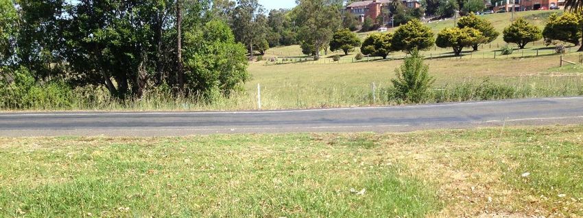
DOCUMENT REGISTER

          Date                Report No.                  Rev                            Comments

      Sep-19                 MSEC1045-02                   A          Draft for submission to Wollondilly Shire Council

                                                                      Final following consultation with Wollondilly Shire
      Sep-19                 MSEC1045-02                   B
                                                                                           Council

References:-
                                 AS/NZS ISO 31000:2009 Risk Management – Principles and guidelines
GHD Geotechnics (2017)           Glencore – Tahmoor Underground – Landslide risk assessment for identified
                                 “steep slopes” – Properties affected by retreat of LW31, GHD Geotechnics,
                                 July 2017.
MSO (2017)                       Managing risks of subsidence – Guide | WHS (Mines and Petroleum Sites)
                                 Legislation, NSW Department of Planning & Environment, Resources
                                 Regulator, Mine Safety Operations, February 2017.
MSEC (2019)                      Tahmoor Coal - Longwalls W1 and W2 - Subsidence Predictions and Impact
                                 Assessments for Natural and Built Features due to the Extraction of the
                                 Proposed Longwalls W1 and W2 in Support of the Extraction Plan Application.
                                 (Report No. MSEC1019, Revision B, July 2019), prepared by Mine Subsidence
                                 Engineering Consultants.
Traffic Professionals (2018) Traffic management plans for Tahmoor Coal near 700 Thirlmere Way, Picton.
Tahmoor Coal (2019)              Risk Assessment Report – Infrastructure. Tahmoor North – Western Domain,
                                 Longwalls West 1 and West 2, April 2019.

WOLLONDILLY SHIRE COUNCIL MANAGEMENT PLAN FOR TAHMOOR COAL LW W1-W2
© MSEC SEPTEMBER 2019 | REPORT NUMBER MSE1945-02 | REVISION B
PAGE ii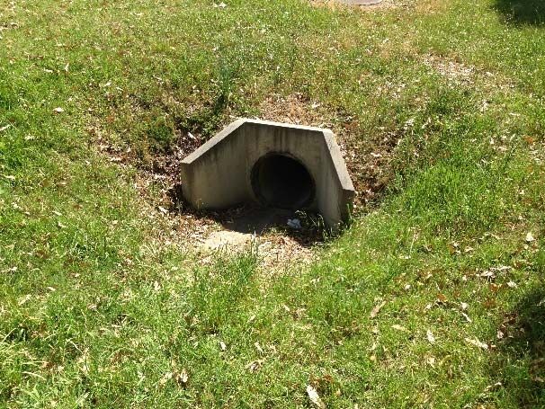
CONTENTS

1.0 INTRODUCTION                                                                                      1
1.1.       Background                                                                                 1
1.2.       Wollondilly Shire Council assets potentially affected by LW W1-W2                          1
1.3.       Consultation                                                                               2
           1.3.1.    Consultation with Wollondilly Shire Council                                      2
           1.3.2.    Consultation with Government Agencies & Key Infrastructure Stakeholders          2
1.4.       Limitations                                                                                2
1.5.       Objectives                                                                                 3
1.6.       Scope                                                                                      3
1.7.       Proposed Mining Schedule                                                                   3
1.8.       Definition of Active Subsidence Zone                                                       3
1.9.       Compensation                                                                               4
2.0 METHOD OF ASSESSMENT OF POTENTIAL MINE SUBSIDENCE IMPACTS                                         5
2.1.       NSW Work Health & Safety Legislation                                                       5
2.2.       General                                                                                    6
           2.2.1.    Consequence                                                                      6
           2.2.2.    Likelihood                                                                       6
           2.2.3.    Hazard                                                                           6
           2.2.4.    Method of assessment of potential mine subsidence impacts                        6
3.0 SUBSIDENCE PREDICTIONS AND ASSESSMENT OF POTENTIAL MINE SUBSIDENCE IMPACTS 7
3.1.       Maximum Predicted Conventional Subsidence Parameters                                       7
3.2.       Comparison of measured and predicted subsidence for single panels                          7
3.3.       Predicted Strain                                                                           7
           3.3.1.    Analysis of strains measured in survey bays                                      8
           3.3.2.    Analysis of strains measured along whole monitoring lines                       9
3.4.       Managing Public Safety                                                                    10
           3.4.1.    Subsidence Impact Management Process for Infrastructure                         11
3.5.       Summary of Potential Impacts                                                              13
3.6.       Identification of subsidence hazards that could give rise to risks to health and safety   13
3.7.       Local roads                                                                               14
           3.7.1.    Predicted subsidence movements                                                  14
           3.7.2.    Potential subsidence impacts on local roads                                     17
           3.7.3.    Thirlmere Way                                                                   19
3.8.       Road drainage culverts                                                                    23
           3.8.1.    Potential subsidence impacts on road drainage culverts                          26
3.9.       Bridges                                                                                   26
4.0 MANAGEMENT OF POTENTIAL IMPACTS                                                                  28
4.1.       Infrastructure Management Group (IMG)                                                     28
4.2.       Development and selection of risk control measures                                        28
4.3.       Selection of risk control measures for council infrastructure                             28
4.4.       Monitoring measures                                                                       29
           4.4.1.    Ground Surveys along streets and centrelines of LW W1-W2                        29
WOLLONDILLY SHIRE COUNCIL MANAGEMENT PLAN FOR TAHMOOR COAL LW W1-W2
© MSEC SEPTEMBER 2019 | REPORT NUMBER MSE1945-02 | REVISION B
PAGE iii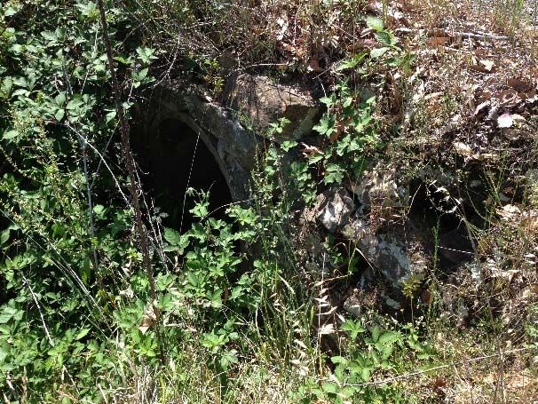
4.4.2.    Far-field Surveys                                  30
           4.4.3.    Visual Inspections                                 31
           4.4.4.    CCTV inspection of culverts and stormwater pipes   31
           4.4.5.    Structural Inspections                             31
           4.4.6.    Changes to Monitoring Frequencies                  31
4.5.       Triggers and Responses                                       31
4.6.       Subsidence Impact Management Procedures                      32
5.0 REPORTING AND COMMUNICATION PLAN                                    36
5.1.       Consultation, Co-operation and Co-ordination                 36
5.2.       IMG Meetings                                                 36
6.0 AUDIT AND REVIEW                                                    37
7.0 RECORD KEEPING                                                      37
8.0 CONTACT LIST                                                        38
APPENDIX A. Drawings and Supporting Documentation                       39

WOLLONDILLY SHIRE COUNCIL MANAGEMENT PLAN FOR TAHMOOR COAL LW W1-W2
© MSEC SEPTEMBER 2019 | REPORT NUMBER MSE1945-02 | REVISION B
PAGE iv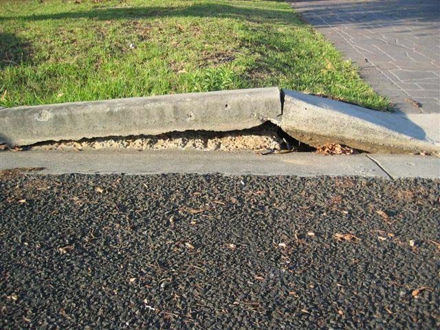
LIST OF TABLES AND FIGURES

Tables
Tables are prefaced by the number of the chapter in which they are presented.
Table No.      Description                                                                                                                                  Page
Table 1.1      Longwall dimensions .................................................................................................................. 1
Table 1.2      Schedule of Mining..................................................................................................................... 3
Table 3.1      Maximum predicted conventional subsidence parameters for LW W1-W2................................ 7
Table 3.2      Summary of Potential Mine Subsidence Impacts..................................................................... 13
Table 3.3      Maximum predicted total conventional subsidence, tilt and curvature for Thirlmere Way ....... 14
Table 3.4      Maximum predicted total conventional subsidence, tilt and curvature for Stoneqaurry Creek
               Road......................................................................................................................................... 14
Table 3.5      Road drainage culverts located within the Study Area............................................................. 23
Table 3.6      Maximum predicted total conventional subsidence, tilt and curvature for road drainage culverts
               ................................................................................................................................................. 23
Table 4.1      Risk Control Procedures during the extraction of Tahmoor Coal LW W1-W2 ......................... 33

Figures
Figures are prefaced by the number of the chapter or the letter of the appendix in which they are presented.
Figure No.         Description                                                                                                                    Page
Fig. 1.1       Diagrammatic Representation of Active Subsidence Zone ........................................................ 4
Fig. 3.1       Distributions of the maximum measured tensile and compressive strains during the Extraction
               of previous longwalls for survey bays located above goaf ......................................................... 8
Fig. 3.2       Distributions of the maximum measured tensile and compressive strains during the extraction
               of previous longwalls for survey bays located above solid coal ................................................. 9
Fig. 3.3       Distributions of maximum measured tensile and compressive strains along monitoring lines
               during the extraction of previous longwalls at the mine ........................................................... 10
Fig. 3.4       Flowchart for Subsidence Impact Management Process ......................................................... 12
Fig. 3.5       Predicted profiles of total subsidence, tilt and curvature along Thirlmere Way after the mining
               of LW W1-W2 ........................................................................................................................... 15
Fig. 3.6       Predicted profiles of total subsidence, tilt and curvature along Stonequarry Creek Road after
               the mining of LW W1-W2 ......................................................................................................... 16
Fig. 3.7       Impacts to road pavements and kerbs in Tahmoor .................................................................. 18
Fig. 3.8       Cross-section through Thirlmere Way and the ridgeline above LW W1 .................................. 19
Fig. 3.9       Installed and proposed extension of survey lines along Thirlmere Way .................................. 20
Fig. 3.10      Observed subsidence along Thirlmere Way during the mining of LWs 31 and 32 as at
               26 August 2019 ........................................................................................................................ 21
Fig. 3.11      Observed changes in distance across Thirlmere Way during the mining of LWs 31 and 32 as
               at 26 August 2019 .................................................................................................................... 22
Fig. 3.12      Culvert TH-C2 on Thirlmere Way west of LW W1 with inlet at top left, side inlet in top right and
               access cover to main culvert in bottom right ............................................................................ 24
Fig. 3.13      Predicted profiles of total subsidence, upsidence and closure along Rumker Gully after the
               mining of LW W1-W2 ............................................................................................................... 25

Drawings
Drawings referred to in this report are included in Appendix A at the end of this report.
Drawing No.                   Description                                                                                                           Revision
MSEC1045-00-01                Monitoring over LW W1-W2                                                                                                         03
MSEC1045-00-02                Far field monitoring                                                                                                             01
MSEC1045-02-01                Local roads, culverts and bridges                                                                                                01

WOLLONDILLY SHIRE COUNCIL MANAGEMENT PLAN FOR TAHMOOR COAL LW W1-W2
© MSEC SEPTEMBER 2019 | REPORT NUMBER MSE1945-02 | REVISION B
PAGE v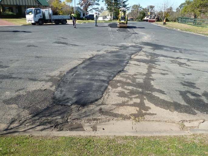
1.0 INTRODUCTION

1.1.      Background
Tahmoor Coal is located approximately 80 km south-west of Sydney in the township of Tahmoor NSW. It is
managed and operated by SIMEC Mining. Tahmoor Coal has previously mined 31 longwalls to the north
and west of the mine’s current location. It is currently mining Longwall 32.
Longwalls West 1 and West 2 (LW W1-W2) are the first two longwalls to be mined in the Western Domain.
The longwall panels are located to the north of the current longwall series, and to the south of Cedar and
Stonequarry Creeks. Infrastructure owned by Wollondilly Shire Council is located within this area.
A summary of the dimensions of LW W1-W2 are provided in Table 1.1.

                                         Table 1.1       Longwall dimensions

                                    Overall void length           Overall void width   Overall tailgate
          Longwall                      including the                including the      chain pillar
                                  installation heading (m)        first workings (m)     width (m)

           LW W1                           1875                          283                  -

           LW W2                           1685                          283                 39

This Management Plan provides detailed information about how the risks associated with mining beneath
the infrastructure will be managed by Tahmoor Coal and Wollondilly Shire Council.
The Management Plan is a live document that can be amended at any stage of mining, to meet the
changing needs of Tahmoor Coal and Wollondilly Shire Council.

1.2.      Wollondilly Shire Council assets potentially affected by LW W1-W2
A map showing the locations of Wollondilly Shire Council infrastructure in relation to LW W1-W2 is shown in
Drawing No. MSEC1045-02-01.
There are a number of local roads located directly above or adjacent to LW W1-W2. The most significant
roads are Thirlmere Way and Stonequarry Creek Road.
There are no bridges within the vicinity of LW W1-W2, though several bridges are predicted to experience
far field movements during the mining of LW W1-W2. The majority of the bridges cross the Main Southern
Railway. Risk control measures to manage potential impacts on this bridge are described in a separate
management plan for the Main Southern Railway, which will be developed in consultation with the
Australian Rail Track Corporation, ARTC. A copy of that management plan can be provided to Wollondilly
Shire Council.
There are many road drainage culverts located above and in the vicinity of LW W1-W2. The culverts
comprise concrete pipes with diameters ranging between 600 mm and 900 mm. Two culverts are located
on Stonequarry Creek Road directly above LW W1 and two culverts are located within Rumker Gully to the
west of LW W1 beneath Stonequarry Creek Road and Thirlmere Way.

WOLLONDILLY SHIRE COUNCIL MANAGEMENT PLAN FOR TAHMOOR COAL LW W1-W2
© MSEC SEPTEMBER 2019 | REPORT NUMBER MSEC1045-02 | REVISION B
PAGE 1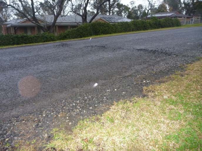
1.3. Consultation
1.3.1. Consultation with Wollondilly Shire Council
Tahmoor Coking Coal Operations regularly consults with Wollondilly Shire Council in relation to mine
subsidence effects from mining. This includes consultation during the development of Subsidence
Management Plans for previous Longwalls 22 to 32, and regular reporting of subsidence movements and
impacts.
Feedback was provided by Wollondilly Shire Council in relation to identification of Council owned buildings
and preparation of a traffic management plan for Thirlmere Way, which was submitted to Council prior to the
installation of survey marks and prior to influence of Longwall 31.
Details regarding consultation and engagement are outlined below:
Meeting with Wollondilly Shire Council, David Talbert (Tahmoor Coal) and Fiona Robinson
(Tahmoor Coal) in September 2019 to discuss the draft Subsidence Management Plan for LW W1-
W2.
Tahmoor Coal will continue to consult regularly with Wollondilly Shire Council during the extraction of
LW W1-W2 in relation to mine subsidence effects from mining.
1.3.2. Consultation with Government Agencies & Key Infrastructure Stakeholders
Government agencies including the NSW Department of Planning & Environment, Resources Regulator,
Mine Safety Operations, Subsidence Advisory NSW and key infrastructure stakeholders including
Endeavour Energy, Sydney Water, Integral, Telstra and Jemena have also been consulted as part of the
Extraction Plan approval process.
1.4. Limitations
This Management Plan is based on the predictions of the effects of mining on surface infrastructure as
provided in Report No. MSEC1019 by Mine Subsidence Engineering Consultants (MSEC, 2019).
Predictions are based on the planned configuration of LW W1-W2 at Tahmoor Coal (as shown in Drawing
No. MSEC1045-02-01), along with available geological information and data from numerous subsidence
studies for longwalls previously mined in the area.
Infrastructure considered in this Plan has been identified from site visits and aerial photographs and from
discussions between Tahmoor Coal representatives and Wollondilly Shire Council.
The impacts of mining on surface and sub-surface features have been assessed in detail. However, it is
recognised that the prediction and assessment of subsidence can be relied upon only to a certain extent.
The limitations of the prediction and assessment of mine subsidence are discussed in report MSEC1019 by
Mine Subsidence Engineering Consultants.
As discussed in the report, there is a low probability that ground movements and their impacts could exceed
the predictions and assessments. However, if these potentially higher impacts are considered prior to
mining, they can be managed. This Management Plan will not necessarily prevent impacts from longwall
mining, but will limit the impacts by establishing appropriate procedures that can be followed should
evidence of increased impacts emerge.
WOLLONDILLY SHIRE COUNCIL MANAGEMENT PLAN FOR TAHMOOR COAL LW W1-W2
© MSEC SEPTEMBER 2019 | REPORT NUMBER MSEC1045-02 | REVISION B
PAGE 2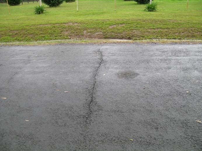
1.5. Objectives
The objectives of this Management Plan are to establish procedures to measure, control, mitigate and repair
potential impacts that might occur to roads, bridges and culverts.
The objectives of the Management Plan have been developed to:-
Ensure the safe and serviceable operation of all surface infrastructure. Public and workplace
safety is paramount. Ensure that the health and safety of people who may be present on public
property or Wollondilly Shire Council property are not put at risk due to mine subsidence.
Avoid disruption and inconvenience, or, if unavoidable, keep to minimal levels.
Monitor ground movements and the condition of infrastructure during mining.
Initiate action to mitigate or remedy potential significant impacts that are expected to occur on the
surface.
Provide a plan of action in the event that the impacts of mine subsidence are greater than those
that are predicted.
Establish a clearly defined decision-making process to ensure timely implementation of risk control
measures for high consequence but low likelihood mine subsidence induced hazards that involve
potential serious injury or illness to a person or persons that may require emergency evacuation,
entry or access restriction or suspension of work activities.
Provide a forum to report, discuss and record impacts to the surface. This will involve Tahmoor
Coal, Wollondilly Shire Council, relevant government agencies as required, and consultants as
required.
Establish lines of communication and emergency contacts.
1.6. Scope
The Management Plan is to be used to protect and monitor the condition of the Wollondilly Shire Council
infrastructure identified to be at risk due to mine subsidence and to ensure that the health and safety of
people who may be present on public property or Wollondilly Shire Council property are not put at risk due
to mine subsidence. The major items at risk are:-
Local roads
Bridges
Culverts
The Management Plan only covers infrastructure that is located within the limit of subsidence, which defines
the extent of land that may be affected by mine subsidence as a result of mining LW W1-W2 only. The
management plan does not include other roads, bridges and culverts owned by Wollondilly Shire Council
which lie outside the extent of this area.
1.7. Proposed Mining Schedule
It is planned that LW W1-W2 will extract coal working south from the northern end. This Management Plan
covers longwall mining until completion of mining in LW W2 and for sufficient time thereafter to allow for
completion of subsidence effects. The current schedule of mining is shown in Table 1.2.
Table 1.2 Schedule of Mining
Longwall Start Date Completion Date
LW W1 October 2019 August 2020
LW W2 September 2020 May 2021
Please note the above schedule is subject to change due to unforeseen impacts on mining progress.
Tahmoor Coal will keep Wollondilly Shire Council informed of changes.
1.8. Definition of Active Subsidence Zone
As a longwall progresses, subsidence begins to develop at a point in front of the longwall face and
continues to develop after the longwall passes. The majority of subsidence movement typically occurs
within an area 150 metres in front of the longwall face to an area 450 metres behind the longwall face.
This is termed the “active subsidence zone” for the purposes of this Management Plan, where surface
monitoring is generally conducted. The active subsidence zone for each longwall is defined by the area
bounded by the predicted 20 mm subsidence contour for the active longwall and a distance of 150 metres in
front and 450 metres behind the active longwall face, as shown by Fig. 1.1.
WOLLONDILLY SHIRE COUNCIL MANAGEMENT PLAN FOR TAHMOOR COAL LW W1-W2
© MSEC SEPTEMBER 2019 | REPORT NUMBER MSEC1045-02 | REVISION B
PAGE 3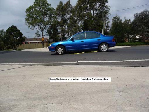
Fig. 1.1        Diagrammatic Representation of Active Subsidence Zone

1.9.      Compensation
The Coal Mine Subsidence Compensation Act 2017 (MSC Act) is administered by Subsidence Advisory
NSW (Mine Subsidence Board).
Currently, under the Coal Mine Subsidence Compensation Act 2017, any claim for mine subsidence
damage needs to be lodged with Subsidence Advisory NSW. Subsidence Advisory NSW staff will arrange
for the damage to be assessed by an independent specialist assessor. If the damage is attributable to mine
subsidence, a scope will be prepared and compensation will be determined. For further details please refer
to Guidelines – Process for Claiming Mine Subsidence Compensation at
www.subsideneadvisory.nsw.gov.au.

WOLLONDILLY SHIRE COUNCIL MANAGEMENT PLAN FOR TAHMOOR COAL LW W1-W2
© MSEC SEPTEMBER 2019 | REPORT NUMBER MSEC1045-02 | REVISION B
PAGE 4
2.0 METHOD OF ASSESSMENT OF POTENTIAL MINE SUBSIDENCE IMPACTS
2.1. NSW Work Health & Safety Legislation
All persons conducting a business or undertaking (PCBUs), including mine operators and contractors, have
a primary duty of care to ensure the health and safety of workers they engage, or whose work activities they
influence or direct. The responsibilities are legislated in Work Health and Safety Act 2011 and the Work
Health and Safety (Mines and Petroleum Sites) Act 2013 and associated Regulations (collectively referred
to as the ‘WHS laws’).
The Work Health and Safety (Mines and Petroleum Sites) Regulation 2014 commenced on 1 February 2015
and contains specific regulations in relation to mine subsidence.
As outlined in the Guide by the NSW Department of Trade & Investment Mine Safety:
“a PCBU must manage risks to health and safety associated with mining operations at the mine by:
complying with any specific requirements under the WHS laws
identifying reasonably foreseeable hazards that could give rise to health and safety risks
ensuring that a competent person assesses the risk
eliminating risks to health and safety so far as is reasonably practicable
minimising risks so far as is reasonably practicable by applying the hierarchy of control measures,
any risks that it is are not reasonably practical to eliminate
maintaining control measures
reviewing control measures.
The mine operator’s responsibilities include developing and implementing a safety management system that
is used as the primary means of ensuring, so far as is reasonably practicable:
the health and safety of workers at the mine, and
that the health and safety of other people is not put at risk from the mine or work carried out as part
of mining operations.”
Detailed guidelines have also been released by the NSW Department of Planning & Environment,
Resources Regulator, Mine Safety Operations (MSO, 2017).
The risk management process has been carried out in accordance with guidelines published by the NSW
Department of Planning & Environment, Resources Regulator, Mine Safety Operations (MSO, 2017). The
following main steps of subsidence risk management have been and will be undertaken, in accordance with
the guidelines.
1. identification and understanding of subsidence hazards
2. assessment of risks of subsidence
3. development and selection of risk control measures
4. implementation and maintenance of risk control measures, and
5. continual improvement and change management.
Each of the above steps have been or will be conducted together with the following processes.
1. consultation, co-operation and co-ordination, and
2. monitoring and review.
This Management Plan documents the risk control measures that are planned to manage risks to health and
safety associated with the mining of LW W1-W2 in accordance with the WHS laws.
WOLLONDILLY SHIRE COUNCIL MANAGEMENT PLAN FOR TAHMOOR COAL LW W1-W2
© MSEC SEPTEMBER 2019 | REPORT NUMBER MSEC1045-02 | REVISION B
PAGE 52.2. General The method of assessing potential mine subsidence impacts in the Management Plan is consistent with the Australian/New Zealand Standard for Risk Management (AS/NZS ISO 31000:2009). The Standard defines the terms used in the risk management process, which includes the identification, analysis, assessment, treatment and monitoring of potential mine subsidence impacts. In this context:- 2.2.1. Consequence ‘The outcome of an event expressed qualitatively or quantitatively, being a loss, injury, disadvantage or gain. There may be a range of possible outcomes associated with an event.’ The consequences of a hazard are rated from negligible to catastrophic. 2.2.2. Likelihood ‘Used as a qualitative description of probability or frequency.’ The likelihood can range from rare to almost certain. 2.2.3. Hazard ‘A source of potential harm or a situation with a potential to cause loss.’ 2.2.4. Method of assessment of potential mine subsidence impacts The method of assessing potential mine subsidence impacts combines the likelihood of an impact occurring with the consequence of the impact occurring. In this Management Plan, the likelihood and consequence are combined via the SIMEC Risk Matrix to determine an estimated level of risk for particular events or situations. A copy of the Risk Matrix is included in the Appendix of this Management Plan. WOLLONDILLY SHIRE COUNCIL MANAGEMENT PLAN FOR TAHMOOR COAL LW W1-W2 © MSEC SEPTEMBER 2019 | REPORT NUMBER MSEC1045-02 | REVISION B PAGE 6
3.0 SUBSIDENCE PREDICTIONS AND ASSESSMENT OF POTENTIAL MINE SUBSIDENCE IMPACTS

3.1.      Maximum Predicted Conventional Subsidence Parameters
Predicted mining-induced conventional subsidence movements were provided in Report No. MSEC1019,
which was prepared in support of Tahmoor Coal’s Extraction Plan for LW W1-W2. A summary of the
maximum predicted total subsidence parameters due to the extraction of LW W1-W2 are provided in
Table 3.1.

          Table 3.1      Maximum predicted conventional subsidence parameters for LW W1-W2

                           Maximum predicted        Maximum predicted   Maximum predicted   Maximum predicted
         Longwall             subsidence                   tilt         hogging curvature   sagging curvature
                                 (mm)                    (mm/m)              (1/km)              (1/km)

       After LW W1                  475                      3.0              0.03                0.06

       After LW W2                  750                      5.5              0.06                0.11

The values provided in the above table are the maximum predicted conventional subsidence parameters
which occur within the general longwall mining area.

3.2.      Comparison of measured and predicted subsidence for single panels
Predictions using MSEC’s Incremental Profile Method have been continually tested and refined during the
mining of previous Longwalls 22 to 31, as described in Report No. MSEC1019.
In this case, LW W1-W2 will be extracting in a new longwall series, which is located to the north of current
LW 32.
Observed subsidence above single panels is typically more variable than above subsequent longwall panels
in a series. The variations are due to different strengths of the overburden strata above the panel, which is
supported on all four sides of the longwall.
A study on observed subsidence above previously extracted single panels at Tahmoor Mine was conducted
by MSEC, with results provided in Report No. MSEC1019.
Whilst a reasonable correlation between measured and predicted subsidence was found for LW 22, which
was the most recently extracted single panel in the Tahmoor North lease, a study of the overall history of
subsidence above single panels at Tahmoor Mine found that actual subsidence above LW W1 could be
greater than predicted. There are also other cases in the Southern Coalfield where measured subsidence
above a single panel has been substantially less than predicted.
It is therefore planned to monitor the development of subsidence during the early stages of extraction of
LW W1 to compare observations with predictions. This will initially be achieved by regular surveys along
the centreline of LW W1, followed by monitoring of subsidence along the Picton-Mittagong Loop Line and
survey lines along local roads.

3.3.      Predicted Strain
The prediction of strain is more difficult than the predictions of subsidence, tilt and curvature. The reason
for this is that strain is affected by many factors, including curvature and horizontal movement, as well as
local variations in the near surface geology, the locations of pre-existing natural joints at bedrock, and the
depth of bedrock. Survey tolerance can also represent a substantial portion of the measured strain, where
the strains are of a low order of magnitude. The profiles of observed strain, therefore, can be irregular even
when the profiles of observed subsidence, tilt and curvature are relatively smooth.
In previous MSEC subsidence reports, predictions of conventional strain were provided based on the best
estimate of the average relationship between curvature and strain. Similar relationships have been
proposed by other authors. The reliability of the strain predictions was highlighted in these reports, where it
was stated that measured strains can vary considerably from the predicted conventional values.
Adopting a linear relationship between curvature and strain provides a reasonable prediction for the
conventional tensile and compressive strains. The locations that are predicted to experience hogging or
convex curvature are expected to be net tensile strain zones and locations that are predicted to experience
sagging or concave curvature are expected to be net compressive strain zones. In the Southern Coalfield, it
has been found that a factor of 15 provides a reasonable relationship between the maximum predicted
curvatures and the maximum predicted conventional strains. At a point, however, there can be
considerable variation from the linear relationship, resulting from non-conventional movements or from the

WOLLONDILLY SHIRE COUNCIL MANAGEMENT PLAN FOR TAHMOOR COAL LW W1-W2
© MSEC SEPTEMBER 2019 | REPORT NUMBER MSEC1045-02 | REVISION B
PAGE 7
normal scatters which are observed in strain profiles. When expressed as a percentage, observed strains
can be many times greater than the predicted conventional strain for low magnitudes of curvature. In this
report, therefore, we have provided a statistical approach to account for the variability, instead of just
providing a single predicted conventional strain.
The data used in an analysis of observed strains included those resulting from both conventional and non-
conventional anomalous movements, but did not include those resulting from valley related movements,
which are addressed separately in this report. The strains resulting from damaged or disturbed survey
marks have also been excluded.
3.3.1. Analysis of strains measured in survey bays
For features that are in discrete locations, such as building structures, farm dams and archaeological sites,
it is appropriate to assess the frequency of the observed maximum strains for individual survey bays.
Predictions of strain above goaf
The survey database has been analysed to extract the maximum tensile and compressive strains that have
been measured at any time during the extraction of Longwalls 22 to 32 at Tahmoor Mine, for survey bays
that were located directly above goaf or the chain pillars that are located between the extracted longwalls,
which has been referred to as “above goaf”.
A histogram of the maximum observed total tensile and compressive strains measured in survey bays
above goaf at Tahmoor Mine is provided in Fig. 3.1. A number of probability distribution functions were
fitted to the empirical data. It was found that a Generalised Pareto Distribution (GPD) provided a good fit to
the raw strain data, and this is also shown in this figure.
Fig. 3.1 Distributions of the maximum measured tensile and compressive strains during the
Extraction of previous longwalls for survey bays located above goaf
The 95 % confidence levels for the maximum total strains that the individual survey bays above goaf
experienced at any time during mining were 1.0 mm/m tensile and 1.8 mm/m compressive. The 99 %
confidence levels for the maximum total strains that the individual survey bays above goaf experienced at
any time during mining are 1.6 mm/m tensile and 3.4 mm/m compressive.
WOLLONDILLY SHIRE COUNCIL MANAGEMENT PLAN FOR TAHMOOR COAL LW W1-W2
© MSEC SEPTEMBER 2019 | REPORT NUMBER MSEC1045-02 | REVISION B
PAGE 8Predictions of strain above solid coal
The survey database has also been analysed to extract the maximum tensile and compressive strains that
have been measured at any time during the extraction of Longwalls 22 to 32 at Tahmoor Mine, for survey
bays that were located outside and within 200 metres of the nearest longwall goaf edge, which has been
referred to as “above solid coal”.
A histogram of the maximum observed tensile and compressive strains measured in survey bays above
solid coal at Tahmoor Mine is provided in Fig. 3.2. The probability distribution functions, based on the fitted
GPDs, have also been shown in this figure.
Fig. 3.2 Distributions of the maximum measured tensile and compressive strains during the
extraction of previous longwalls for survey bays located above solid coal
The 95 % confidence levels for the maximum total strains that the individual survey bays above solid coal
experienced at any time during mining were 0.7 mm/m tensile and 0.5 mm/m compressive. The 99 %
confidence levels for the maximum total strains that the individual survey bays above solid coal experienced
at any time during mining are 1.0 mm/m tensile and 0.8 mm/m compressive.
3.3.2. Analysis of strains measured along whole monitoring lines
For linear features such as roads, cables and pipelines, it is more appropriate to assess the frequency of the
maximum observed strains along whole monitoring lines, rather than for individual survey bays. That is, an
analysis of the maximum strains measured anywhere along the monitoring lines, regardless of where the
strain actually occurs.
A histogram of maximum measured total tensile and compressive strains measured anywhere along the
monitoring lines, at any time during or after the extraction of the previous longwalls at the mine, is provided
in Fig. 3.3.
WOLLONDILLY SHIRE COUNCIL MANAGEMENT PLAN FOR TAHMOOR COAL LW W1-W2
© MSEC SEPTEMBER 2019 | REPORT NUMBER MSEC1045-02 | REVISION B
PAGE 9Fig. 3.3 Distributions of maximum measured tensile and compressive strains along
monitoring lines during the extraction of previous longwalls at the mine
It can be seen from the above figure, that 33 of the 61 monitoring lines (i.e. 54 %) had recorded maximum
total tensile strains of 1.0 mm/m, or less, and that 57 monitoring lines (i.e. 93 %) had recorded maximum
total tensile strains of 2.0 mm/m, or less. It can also be seen, that 40 of the 61 monitoring lines (i.e. 66 %)
had recorded maximum compressive strains of 2.0 mm/m, or less, and that 54 of the monitoring lines
(i.e. 89 %) had recorded maximum compressive strains of 4.0 mm/m, or less.
3.4. Managing Public Safety
The primary risk associated with mining beneath Wollondilly Shire Council infrastructure is public safety.
Tahmoor Coal has previously directly mined beneath or adjacent to more than 1900 houses and civil
structures, commercial and retail properties, the Main Southern Railway and local roads and bridges. It has
implemented extensive measures prior to, during and after mining to ensure that the health and safety of
people have not been put at risk due to mine subsidence. People have not been exposed to immediate and
sudden safety hazards as a result of impacts that have occurred due to mine subsidence movements.
Emphasis is placed on the words “immediate and sudden” as in rare cases, some structures have
experienced severe impacts, but the impacts did not present an immediate risk to public safety as they
developed gradually with ample time to repair the structure.
In the case of this Subsidence Management Plan, the potential for impacts on public safety has been
assessed on a case by case basis. The assessments include a geotechnical engineer for steep slopes.
WOLLONDILLY SHIRE COUNCIL MANAGEMENT PLAN FOR TAHMOOR COAL LW W1-W2
© MSEC SEPTEMBER 2019 | REPORT NUMBER MSEC1045-02 | REVISION B
PAGE 103.4.1. Subsidence Impact Management Process for Infrastructure
Tahmoor Coal has developed and acted in accordance with a subsidence management plan to manage
potential impacts during the mining of Longwalls 22 to 32. The management strategy has been reviewed
and updated based on experiences gained during the mining of Longwalls 22 to 32 and the strategy for
LW W1-W2 includes the following process:
1. Regular consultation with Wollondilly Shire Council before, during and after mining.
2. Site-specific investigations.
3. Implementation of mitigation measures following inspections by a structural engineer, a mine
subsidence engineer, and, if required, a geotechnical engineer or other specialist engineer.
4. Surveys and inspections during mining within the active subsidence area:
Detailed visual inspections and vehicle-based inspections along the streets
Ground surveys along streets
Specific ground surveys and visual inspections, where recommended by an engineer based
on the inspections and assessments.
A flowchart illustrating the subsidence impact management process prior to, during and after Wollondilly
Shire Council infrastructure experiences mine subsidence movements is shown in Fig. 3.4.
WOLLONDILLY SHIRE COUNCIL MANAGEMENT PLAN FOR TAHMOOR COAL LW W1-W2
© MSEC SEPTEMBER 2019 | REPORT NUMBER MSEC1045-02 | REVISION B
PAGE 11Process review (implement learnings or
improvements based on new knowledge)
Inspection by
WSC infrastructure
geotechnical
is on or near steep
engineer
slope
Identification of
geological
structures
Implement Implement
mitigation and maintain
Identification IMG develop
measures (if risk control
of subsidence Management
Identification Inspection Development req’d) prior to measures
hazards and Plan in
of WSC by and selection LW face during and
Bridges consultation
infrastructure structural assessment of risk control approaching after mining
of risks of with WSC
(Extraction engineer measures structure, as (monitoring,
Plan subsidence defined in reporting,
LW W1-W2) Management triggers,
Plan responses)
WSC raises concerns Immediate
Review adequacy
about structure(s) or meeting between
and effectiveness
other feature Tahmoor Coal
Hazard identified that of risk control
and WSC to
involves potential serious measures
implement
injury or illness to a and
emergency
person or persons, and Forecast whether
procedures.
cannot be controlled continued mining is
likely to cause
impacts to health
and safety
Implement learnings or improvements
based on new knowledge during mining
Fig. 3.4 Flowchart for Subsidence Impact Management Process
WOLLONDILLY SHIRE COUNCIL MANAGEMENT PLAN FOR TAHMOOR COAL LW W1-W2
© MSEC SEPTEMBER 2019 | REPORT NUMBER MSEC1045-02 | REVISION B
PAGE 123.5. Summary of Potential Impacts
A summary of potential impacts on Wollondilly Shire Council infrastructure is provided in Table 3.2. The
summary is consistent with the risk assessment undertaken by Tahmoor Coal (2019). The results of the
risk assessment are included in the Appendix.
Table 3.2 Summary of Potential Mine Subsidence Impacts
Level of Potential
Risk Likelihood Consequence
Impact
Local Roads
Minor cracking or heaving of
LIKELY MINOR MEDIUM
pavement, kerbs and gutters
Major cracking or heaving of
UNLIKELY MODERATE MEDIUM
pavement, kerbs and gutters
Thirlmere Way
Slope instability causing loss of
support to road resulting in tension UNLIKELY MINOR LOW
cracking in road surface
Culverts and stormwater drain
Cracking or spalling of pipework UNLIKELY MINOR LOW
Additional information on each potential impact is provided below.
3.6. Identification of subsidence hazards that could give rise to risks to health and
safety
Clause 34 of the Work Health and Safety Regulation (2017) requires that the duty holder (in this case
Tahmoor Coking Coal Operations), in managing risks to health and safety, must identify reasonably
foreseeable hazards that could give rise to risks to health and safety.
This section of the Management Plan summarises hazards that have been identified in Chapter 3, which
could give rise to risks to health and safety of people on Council infrastructure.
Using the processes described in Section 3.4 of this Management Plan, mine subsidence hazards have
been identified, investigated and analysed in a systematic manner by examining each aspect of
infrastructure, as described in Sections 3.7 to 3.9 of this Management Plan. Each of the aspects below
could potentially experience mine subsidence movements that give rise to risks to the health and safety of
people.
Local roads
Bridges
Road drainage culverts.
The following mine subsidence hazards were identified that could give rise to risks to health and safety on
Council infrastructure due to the extraction of LW W1-W2.
Potential major mine subsidence damage to local roads, particularly the main roads where vehicles
travel at a higher speed (refer Section 3.7);
Potential slope instability beneath Thirlmere Way (refer Section 3.7.3); and
Potential damage or loss of services to culverts (refer Section 3.8).
The identification and risk assessment process took into account the location of infrastructure relative to
LW W1-W2 and the associated timing and duration of the subsidence event, as described in Section 1.8 of
this Management Plan.
Whilst mine subsidence predictions and extensive past experiences from previous mining at Tahmoor Mine
were taken into account, the identification and risk assessment process recognised that there are
uncertainties in relation to predicting subsidence movements, and uncertainties in how mine subsidence
movements may adversely impact Council infrastructure, as discussed in Section 1.4 and Chapter 3 of this
Management Plan. In this case, creeks have been mapped that intersect local roads, and Thirlmere Way is
situated on top of a ridgeline.
WOLLONDILLY SHIRE COUNCIL MANAGEMENT PLAN FOR TAHMOOR COAL LW W1-W2
© MSEC SEPTEMBER 2019 | REPORT NUMBER MSEC1045-02 | REVISION B
PAGE 13Tahmoor Coal has considered the outcomes of the hazard identification and risk assessment process when
developing measures to manage potential impacts on the health and safety of people, and potential impacts
on Council property in general. These are described in Chapter 4 of this Management Plan.
3.7. Local roads
There are a number of local roads that are located directly above or adjacent to LW W1-W2, as shown in
Drawing No. MSEC1045-02-01.
Thirlmere Way
One of the main roads linking the townships of Thirlmere and Picton. The finishing end of LW W1 is
located directly beneath a short section of Thirlmere Way.
Stonequarry Creek Road
The main road within the Stonequarry Estate to the north of Thirlmere Way. The northern end of the
road is located directly above LW W1.
Carramar Close, Attunga Close and Booyong Close
These streets are located directly above and adjacent to LW W1-W2.
Barkers Lodge Road
A small section is located within the Study Area and may experience minor subsidence movements
during the extraction of W W1-W2.
3.7.1. Predicted subsidence movements
The local roads are spread across LW W1 and, therefore, they will collectively experience the full range of
predicted subsidence movements, as described in Section 3.1. A discussion on the expected range of
tensile and compressive strains during the mining of LW W1-W2 is provided in Section 3.3.
The predicted profiles of conventional subsidence, tilt and curvature along Thirlmere Way and Stonequarry
Creek Road are shown in Fig. 3.5 and Fig. 3.6, respectively.
A summary of the maximum predicted conventional subsidence, tilt and curvature for Thirlmere Way and
Stonequarry Creek Road, is provided in Table 3.3 and Table 3.4, respectively. The values are the
maximum predicted parameters anywhere along the sections of roads located within the predicted limit of
vertical subsidence for LW W1-W2.
Table 3.3 Maximum predicted total conventional subsidence, tilt and curvature for Thirlmere Way
Maximum predicted Maximum predicted Maximum predicted
Maximum predicted
Longwall total subsidence total hogging total sagging
total tilt (mm/m)
(mm) curvature (1/km) curvature (1/km)
After LW W1 80 < 0.5 0.01 < 0.01
After LW W2 100 < 0.5 0.02 < 0.01
Table 3.4 Maximum predicted total conventional subsidence, tilt and curvature for
Stoneqaurry Creek Road
Maximum predicted Maximum predicted Maximum predicted
Maximum predicted
Longwall total subsidence total hogging total sagging
total tilt (mm/m)
(mm) curvature (1/km) curvature (1/km)
After LW W1 425 2.0 0.02 0.05
After LW W2 700 3.0 0.03 0.05
WOLLONDILLY SHIRE COUNCIL MANAGEMENT PLAN FOR TAHMOOR COAL LW W1-W2
© MSEC SEPTEMBER 2019 | REPORT NUMBER MSEC1045-02 | REVISION B
PAGE 14Fig. 3.5 Predicted profiles of total subsidence, tilt and curvature along Thirlmere Way
after the mining of LW W1-W2
WOLLONDILLY SHIRE COUNCIL MANAGEMENT PLAN FOR TAHMOOR COAL LW W1-W2
© MSEC SEPTEMBER 2019 | REPORT NUMBER MSEC1045-02 | REVISION B
PAGE 15Fig. 3.6 Predicted profiles of total subsidence, tilt and curvature along Stonequarry Creek Road
after the mining of LW W1-W2
WOLLONDILLY SHIRE COUNCIL MANAGEMENT PLAN FOR TAHMOOR COAL LW W1-W2
© MSEC SEPTEMBER 2019 | REPORT NUMBER MSEC1045-02 | REVISION B
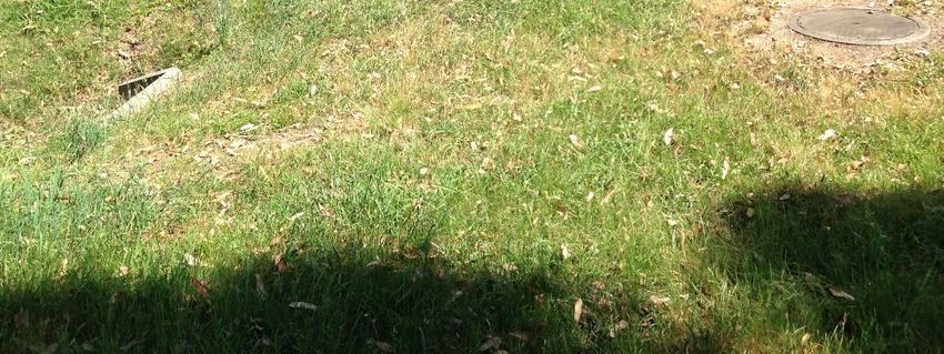
PAGE 163.7.2. Potential subsidence impacts on local roads Extensive monitoring of road pavements has been undertaken during the extraction of Longwalls 22 to 32 at Tahmoor. This includes a network of ground monitoring lines and weekly visual inspections in areas that are experiencing active subsidence. Approximately 28 km of asphaltic pavement lie directly above the extracted longwalls and a total of 52 impact sites have been reported. The observed rate of impact equates to an average of one impact for every 540 m of pavement. The impacts have not presented a public safety risk, and the majority of the impacts have been minor in nature. Impacts have also been observed to concrete kerbs, gutters and drainage pits. The impacts are most commonly focussed around driveway laybacks and involve cracking, spalling or buckling. The most severe impacts were located where substantial non-conventional movements had developed. These impact sites were identified using visual and ground monitoring and remediation was undertaken during active subsidence to maintain the roads in safe and serviceable condition. Traffic signs and other road infrastructure have not previously experienced impacts due to mine subsidence. It is expected that minor impacts will occur to the local roads during the extraction of LW W1-W2, similar in frequency and severity to those experienced during the mining of Longwalls 22 to 32. As described in Sections 1.8 and 3.4, mine subsidence movements will develop gradually as mining progresses. Impacts on the asphaltic pavements will also develop gradually due to their flexible nature, as has been previously observed during the mining of Longwalls 22 to 32 at Tahmoor Mine. WOLLONDILLY SHIRE COUNCIL MANAGEMENT PLAN FOR TAHMOOR COAL LW W1-W2 © MSEC SEPTEMBER 2019 | REPORT NUMBER MSEC1045-02 | REVISION B PAGE 17
Lintina Street (most severe to date)                            Remembrance Drive (hump at roundabout)

      Brundah Road (typical impact to pavement)                           Patterson Street (typical impact to kerb)

                      Struan Street                                                    Moorland Rd
                                                    Photographs courtesy of Tahmoor Coking Coal Operations and Colin Dove

                        Fig. 3.7       Impacts to road pavements and kerbs in Tahmoor

WOLLONDILLY SHIRE COUNCIL MANAGEMENT PLAN FOR TAHMOOR COAL LW W1-W2
© MSEC SEPTEMBER 2019 | REPORT NUMBER MSEC1045-02 | REVISION B
PAGE 18
3.7.3. Thirlmere Way
Thirlmere Way runs along the side of a ridge near the southern (i.e. finishing) end of LW W1, with steep
slopes located above and below the road. The same section of road has experienced subsidence
movements during the mining of LW 31 with no impacts observed and at the time of preparing this
Management Plan, the pavement will soon experience subsidence movements due to the extraction of
LW 32.
It is possible that surface cracking or slippage could develop on the side of the ridge due to the extraction of
LW W1 and that these may intersect with Thirlmere Way. A cross-section through Thirlmere Way and the
ridgeline above the finishing end of LW W1 is provided in Fig. 3.8.
Thirlmere Way narrows in this section, with no shoulders on either side of the pavement, limiting the access
for monitoring and undertaking repairs. The traffic along this section of road, therefore, will need to be
managed to allow surveys and inspections to be undertaken and undertake any required remediation works.
Fig. 3.8 Cross-section through Thirlmere Way and the ridgeline above LW W1
Tahmoor Coal engaged geotechnical engineer GHD Geotechnics to undertake a geotechnical assessment
of the steep slopes along Thirlmere Way (GHD Geotechnics, 2017). The existing conditions along
Thirlmere Way were appraised using RMS methodology (RMS Guide to Slope Risk Management,
Version 4), where ARL1 is a high risk, and ARL5 is low.
A scenario of approximately 20m3 of rock or soil debris flowing onto the road from the cuttings was
assessed as ARL3.
A scenario of loss of embankment edge leading to step in the road pavement was assessed as
assessed as ARL4.
The assessments were repeated taking into account the potential effects from subsidence. The
assessments did not change from the current condition.
Prior to the influence of LW 31, survey marks T101 to T127 were installed and surveyed along Thirlmere
Way where steep slopes are located above and below the road. The survey line has recently been
extended to Peg T159 to monitor changes during the mining of LW32. A map showing the locations of
survey pegs is provided in Fig. 3.9.
Weekly surveys are currently being conducted as the LW32 face approaches the road. The results of
surveys as at 26 August 2019 are shown in Fig. 3.10. It can be seen that low level subsidence was
observed during and after the mining of LW31. Additional residual subsidence has developed at survey
marks T101 to T127 during the period of time between the cessation of surveys for LW31 and the
recommencement of surveys for LW32. Mining-induced tilts and strains remain very small.
Six survey pegs were installed on the opposite side of Thirlmere Way from the main survey line to monitor
changes in horizontal distances across the pavement. A map showing the locations of the six cross
sections is provided in Fig. 3.9. The results of surveys as at 26 August 2019 are shown in Fig. 3.11. It can
be seen that some changes were observed during the period of time between the cessation of surveys for
LW31 and the recommencement of surveys for LW32. Minor changes have generally been observed since
surveys recommenced for LW32, with minor growth in ground shortening between Pegs T116A and T117,
which are oriented in a direction along the pavement.
No impacts have been observed to the pavement to date.
WOLLONDILLY SHIRE COUNCIL MANAGEMENT PLAN FOR TAHMOOR COAL LW W1-W2
© MSEC SEPTEMBER 2019 | REPORT NUMBER MSEC1045-02 | REVISION B
PAGE 19Fig. 3.9 Installed and proposed extension of survey lines along Thirlmere Way WOLLONDILLY SHIRE COUNCIL MANAGEMENT PLAN FOR TAHMOOR COAL LW W1-W2 © MSEC SEPTEMBER 2019 | REPORT NUMBER MSEC1045-02 | REVISION B PAGE 20
Fig. 3.10      Observed subsidence along Thirlmere Way during the mining of LWs 31 and 32 as at
                                          26 August 2019

WOLLONDILLY SHIRE COUNCIL MANAGEMENT PLAN FOR TAHMOOR COAL LW W1-W2
© MSEC SEPTEMBER 2019 | REPORT NUMBER MSEC1045-02 | REVISION B
PAGE 21
Fig. 3.11 Observed changes in distance across Thirlmere Way during the mining of LWs 31
and 32 as at 26 August 2019
Tahmoor Coal has developed and selected risk control measures in consultation, co-ordination and
co-operation with Wollondilly Shire Council in accordance with WHS legislation. In this instance, there are
no reasonably practicable controls which could eliminate, substitute or isolate the identified risks, nor
engineering controls that could put in place a structure or item that prevents or minimises risks. Tahmoor
Coal has identified controls that will manage potential issues associated with the identified risks, as
described by GHD Geotechnics.
Local 2D survey of subsidence along Thirlmere Way with locations of pegs shown in Fig. 3.9. Prior
to the influence of LW W1, the survey line will be extended to the north to monitor subsidence
movements during and after the mining of LW W1-W2.
Local 2D survey of changes in horizontal distance at six cross-sections across the Thirlmere Way
road pavement where the steep slopes are present. The locations of the install cross-sections are
shown in Fig. 3.9.
Visual inspections along Thirlmere Way.
Additional surveys and/or inspections, if triggered by monitoring results.
Repair of pavement if damage is observed.
As a last resort, temporary closure of Thirlmere Way if a hazard has been identified that involves
potential serious injury or illness to a person or persons and cannot be controlled.
Development of traffic management plan to manage traffic in the event that mining-induced
damage develops along the road and requires repair.
With the implementation of the above management strategy, Tahmoor Coal will ensure that the health and
safety of people along Thirlmere Way will not be put at risk due to differential mine subsidence movements
due to the extraction of LW W1-W2.
WOLLONDILLY SHIRE COUNCIL MANAGEMENT PLAN FOR TAHMOOR COAL LW W1-W2
© MSEC SEPTEMBER 2019 | REPORT NUMBER MSEC1045-02 | REVISION B
PAGE 22A traffic management plan (Traffic Professionals, 2018) has been developed for the installation and
continued monitoring of survey pegs. Visual inspections of the pavement can be undertaken whilst the
surveys are conducted. The traffic management plan has been appended to this Management Plan.
3.8. Road drainage culverts
There are four road drainage culverts located above and in the vicinity of LW W1-W2. The culverts are
single reinforced concrete pipes (RCP) with diameters ranging between 600 mm and 900 mm.
A summary of these culverts is provided in Table 3.5.
Table 3.5 Road drainage culverts located within the Study Area
Road Culvert ref. Location Size and type
SC-C1 190 m west of LW W1 Single RCP 600 mm dia.
Stonequarry Creek Road SC-C2 Directly above LW W1 Single RCP 600 mm dia.
SC-C3 Directly above LW W1 Single RCP 900 mm dia.
Thirlmere Way TH-C2 130 m west of LW W1 Single RCP 800 mm dia.
Culvert TH-C2 is an 800 mm diameter RCP culvert located on Rumker Gully approximately 130 metres to
the west of LW W1. Photographs of the culvert are shown in Fig. 3.12, where it can be seen that the inlet
(top left image) is an RCP with broken masonry headwall. On the downstream (northern) side of Thirlmere
Way, a broad drainage ditch collects surface water run off via a side inlet (top right image) and directs it into
the culvert at a buried tee connection. An access cover is located above the main culvert, as shown in the
bottom image.
The culvert then continues beneath private property before linking up with Culvert SC-C1 and discharging
into Rumker Gully.
A summary of the maximum predicted conventional subsidence, tilt and curvature for road drainage culverts
is provided in Table Table 3.6, respectively. The values are the maximum predicted values within 20 m of
each of the culverts at any time during or after the extraction of LW W1-W2.
Table 3.6 Maximum predicted total conventional subsidence, tilt and curvature
for road drainage culverts
Maximum predicted Maximum predicted Maximum predicted
Maximum predicted
Culvert total vertical total hogging total sagging
total tilt (mm/m)
subsidence (mm) curvature (km-1) curvature (km-1)
SC-C1 40 < 0.5 < 0.01 < 0.01
SC-C2 625 3.5 0.05 0.05
SC-C3 700 2.5 0.02 0.05
TH-C2 30 < 0.5 < 0.01 < 0.01
The predicted profiles of total vertical subsidence, upsidence and closure along Rumker Gully are shown in
Fig. 3.13. The locations of the road crossings are indicated in this figure.
The predicted valley related effects for Culvert TH-C2 are 50 mm upsidence and 80 mm closure. The
predicted valley related effects for Culvert SC-C1 at Stonequarry Creek Road are 50 mm upsidence and
closure.
The maximum predicted valley related effects for Culverts SC-C2 and SC-C3 along Stonequarry Creek
Road at Carramar Close and Booyong Close are also 50 mm upsidence and closure.
WOLLONDILLY SHIRE COUNCIL MANAGEMENT PLAN FOR TAHMOOR COAL LW W1-W2
© MSEC SEPTEMBER 2019 | REPORT NUMBER MSEC1045-02 | REVISION B
PAGE 23Fig. 3.12 Culvert TH-C2 on Thirlmere Way west of LW W1 with inlet at top left, side inlet in top
right and access cover to main culvert in bottom right
WOLLONDILLY SHIRE COUNCIL MANAGEMENT PLAN FOR TAHMOOR COAL LW W1-W2
© MSEC SEPTEMBER 2019 | REPORT NUMBER MSEC1045-02 | REVISION B
PAGE 24Fig. 3.13 Predicted profiles of total subsidence, upsidence and closure along
Rumker Gully after the mining of LW W1-W2
WOLLONDILLY SHIRE COUNCIL MANAGEMENT PLAN FOR TAHMOOR COAL LW W1-W2
© MSEC SEPTEMBER 2019 | REPORT NUMBER MSEC1045-02 | REVISION B
PAGE 253.8.1. Potential subsidence impacts on road drainage culverts
The maximum predicted tilt for Culverts SC-C1 to SC-C3 and TH-C2 is 3.5 mm/m (i.e. 0.35 %, or 1 in 285).
It is unlikely that the mining-induced tilts would result in adverse impacts on the serviceability of these
culverts, as the changes in grade are less than 1 %. If the flow of waters through any of the culverts were
adversely affected, due to the extraction of LW W1-W2, these could be remediated by re-levelling the
affected culverts.
The predicted curvatures and strains could be of sufficient magnitudes to result in cracking in the culverts or
the headwalls. It is unlikely, however, that these movements would adversely impact on the stabilities or
structural integrities of the culverts.
The drainage culverts are located along the tributaries and therefore could experience valley related effects.
The drainage culverts are orientated along the alignments of the tributaries and, therefore, the upsidence
and closure movements are orientated perpendicular the main axes of the culverts and unlikely to result in
adverse impacts.
Previous experience of mining beneath culverts in the NSW coalfields, at similar depths of cover, indicates
that the incidence of impacts is low. Impacts have generally been limited to cracking in the concrete
headwalls which can be readily remediated. In some cases, however, cracking in the culvert pipes occurred
which required the culverts to be replaced.
There have been no reports of impacts to road drainage culverts during the mining of Longwalls 22 to 32,
with the exception of a culvert headwall on Bridge Street during the mining of Longwall 31. The low
incidence of impacts is understandable as the culverts are typically constructed of jointed circular concrete
pipes, which are able to tolerate substantial differential ground movements. While it is possible that the
culverts could experience physical impacts such as cracking, the probability is considered low.
The potential impacts on the drainage culverts could be managed by visual inspection and, where required,
any affected culverts can be repaired or replaced. Visual inspections of Culvert TH-C2 will be conducted by
CCTV inspection and include the pipes that extend from Thirlmere Way to Culvert SC-C1 and the discharge
into Rumker Gully downstream of Stonequarry Creek Road. If the stormwater pipes experience cracking
due to mine subsidence movements, the pipes can be repaired in situ by inserting a liner or in the worst
case, replacing the damaged pipe section.
Tahmoor Coal and Wollondilly Shire Council have developed and acted in accordance with an agreed risk
management plan to manage potential impacts to roads drainage culverts during the mining of Longwalls 22
to 32. The management plans provide for visual monitoring of the culverts.
Survey lines will be installed along the local roads and monitoring data will be used to determine whether
the culverts have experienced significant differential subsidence movements. If any adverse impacts were
to occur as the result of mining, the affected culverts could be repaired or replaced.
3.9. Bridges
LW W1-W2 do not extract directly beneath any bridges, though some bridges are predicted to experience
far field subsidence movements during the mining of LW W1-W2.
Bridge Street Overbridge over Main Southern Railway
This bridge has been mined directly beneath by Longwall 29 and has experienced additional
subsidence movements during the extraction of Longwalls 30 to 32. This rail bridge is located 1.1 km
south of the proposed LW W1. Risk control measures to manage potential impacts on this bridge are
described in a separate management plan for the Main Southern Railway, which has been developed in
consultation with the Australian Rail Track Corporation, ARTC. A copy of the management plan can be
provided to Wollondilly Shire Council.
Survey marks have been placed on the bridge abutments and the bridge deck on both sides. They
have been regularly surveyed during the mining of Longwalls 30 to 32. The survey marks will be re-
surveyed at the completion of LW W1 and LW W2.
Thirlmere Way Rail Underbridge beneath Main Southern Railway
This bridge is located approximately 625 metres to the eastern side of Longwall 32 and 850 metres
from LW W2. It is predicted to experience less than 20 mm vertical subsidence and minor absolute and
differential horizontal movements during the extraction of LW W1-W2. Risk control measures to
manage potential impacts on this bridge are described in a separate management plan for the Main
Southern Railway, which has been developed in consultation with ARTC. A copy of that management
plan can be provided to Wollondilly Shire Council.
Survey marks have been placed across the base of the bridge abutment on both sides. A ground
survey mark has been installed adjacent to the bridge and its absolute position has been surveyed on a
WOLLONDILLY SHIRE COUNCIL MANAGEMENT PLAN FOR TAHMOOR COAL LW W1-W2
© MSEC SEPTEMBER 2019 | REPORT NUMBER MSEC1045-02 | REVISION B
PAGE 26You can also read