TCS 015:2021 Variable Message Signs - for
←
→
Page content transcription
If your browser does not render page correctly, please read the page content below
TCS 015:2021

Specification

Variable Message Signs
for
Fixed Installations
Supply and installation

May 2021
Revision: A
Department of Transport (Roads)

      TCS 015:2021

                                                          Foreword

                                                          This specification has been developed by DoT (Roads).
                                                          It is one of a number of technical specifications, and
                                                          associated standard drawings, which set out the
                                                          requirements for roadside ITS devices, traffic signal
                                                          equipment and other electrical equipment and associated
                                                          devices and control systems.

                                                          This specification is intended for use in all relevant
                                                          works undertaken by or on behalf of DoT (Roads).

                                                          VicRoads Standard Drawings, Specifications and
                                                          Guidelines are available for downloading from the
                                                          VicRoads website:
                                                          https://www.vicroads.vic.gov.au/business-and-
                                                          industry/technical-publications/electrical-and-intelligent-
                                                          transport-systems

      COPYRIGHT                                           Specification updates. VicRoads specifications and
                                                          associated standard drawings are subject to periodic
      © Road Corporation trading as DoT (Roads). All      review. To keep the specifications up to date,
      rights reserved.                                    amendments or new editions are issued as necessary. It
                                                          is therefore important for users of VicRoads
      This document remains the property of DoT           specifications to ensure that they have the latest version
      (Roads). No part of this document may be            and associated amendments.
      reproduced or copied in any form or by any means,
      electronic or mechanical, including photocopying,
      without the written permission of VicRoads

                                                          Intelligent Transport Systems
                                                          60 Denmark Street Kew 3101

                                                          ITS_Improvements_and_standards@roads.vic.gov.au

                                                     TCS 015:2021
 Page 2 of 52                                                                                                           Rev: A
                                                 Variable Message Signs
Department of Transport (Roads)
Revision History
Version Revision Date Author Description
2000 ITS Version 4 released
2004 ITS Version 5 released
2011 ITS Version 6 released
2016 A Feb 2016 ITS Specification fully revised and reformatted
2021 A May 2021 ITS - Revised and updated to reflect new AS
4852.1:2019
- Updated to DoT template
- Replace references to RMS with
TfNSW
- Added requirement for type approval
- Expansion of preparation and
installation sections
TCS 015:2021
Page 3 of 52 Rev: A
Variable Message SignsDepartment of Transport (Roads)
Contents
SECTION 1 SCOPE AND GENERAL..................................................................................... 6
1.1 SCOPE ....................................................................................................................................................... 6
1.2 GENERAL ................................................................................................................................................. 6
1.3 CCTV CAMERA ....................................................................................................................................... 7
1.4 INTELLECTUAL PROPERTY .................................................................................................................. 7
1.5 TYPE APPROVAL .................................................................................................................................... 7
1.6 ACRONYMS ............................................................................................................................................. 8
SECTION 2 - RELATED SPECIFICATIONS AND DRAWINGS ............................................ 9
2.1 AUSTRALIAN STANDARDS................................................................................................................... 9
2.2 DOT (ROADS) SPECIFICATIONS ........................................................................................................... 9
2.3 DOT (ROADS) STANDARD DRAWINGS ............................................................................................... 9
2.4 ADDITIONAL SPECIFICATIONS ...........................................................................................................10
2.5 EXCEPTIONS AND CLARIFICATIONS TO AS 4852.1:2019 .................................................................10
SECTION 3 MECHANICAL REQUIREMENTS ................................................................. 11
3.1 GENERAL ................................................................................................................................................11
3.2 SIGN ENCLOSURE .................................................................................................................................11
3.3 ROADSIDE CABINET .............................................................................................................................11
3.4 SIGN SUPPORT STRUCTURE AND ASSOCIATED FOOTING .............................................................12
SECTION 4 ELECTRICAL REQUIREMENTS ................................................................... 13
4.1 GENERAL ................................................................................................................................................13
4.2 OPERATING VOLTAGE .........................................................................................................................13
4.3 INTERNAL PROTECTION ......................................................................................................................13
4.4 SIGN INTERNAL POWER DISTRIBUTION ...........................................................................................13
4.5 POWER CONSUMPTION ........................................................................................................................14
4.6 EMC COMPLIANCE................................................................................................................................14
4.7 COMMUNICATIONS EQUIPMENT .......................................................................................................14
SECTION 5 DISPLAY AND OPTICAL REQUIREMENTS ............................................... 15
5.1 GENERAL ................................................................................................................................................15
5.2 DISPLAY CHARACTERS .......................................................................................................................15
5.3 DISPLAY DIMENSIONAL REQUIREMENTS ........................................................................................15
5.4 CHARACTER FORMATS........................................................................................................................16
5.5 DISPLAY CHANGES...............................................................................................................................16
5.6 COLOUR SIGNS ......................................................................................................................................16
5.7 GRAPHICS REQUIREMENTS.................................................................................................................17
5.8 SIGN DIMMING CONTROL ...................................................................................................................17
5.9 CONSPICUITY DEVICES .......................................................................................................................17
5.10 LED PIXEL LIFESPAN REQUIREMENTS..............................................................................................17
SECTION 6 COLOUR PICTOGRAM .................................................................................. 18
6.1 GENERAL ................................................................................................................................................18
6.2 PICTOGRAM DISPLAY REGION ...........................................................................................................18
6.3 PICTOGRAM OPTICAL REQUIREMENTS ............................................................................................19
6.3.1 Optical Requirements.............................................................................................................19
6.3.2 Colormetric Requirements .....................................................................................................19
TCS 015:2021
Page 4 of 52 Rev: A
Variable Message SignsDepartment of Transport (Roads)
6.3.3 Lifetime Performance Requirements.......................................................................................19
6.4 DISPLAY CHANGES...............................................................................................................................19
SECTION 7 OPERATION AND CONTROL ........................................................................ 20
7.1 GENERAL ................................................................................................................................................20
7.2 SIGN CONTROL PERFORMANCE AND CAPABILITY ........................................................................20
7.3 SIGN CONTROLLER (SC).......................................................................................................................20
7.4 ADMINISTRATION AND CONFIGURATION TOOL ............................................................................21
7.5 RESET ......................................................................................................................................................25
7.6 SIGN CONTROLLER PARAMETER DEFAULT SETTINGS ..................................................................26
7.7 ETHERNET ..............................................................................................................................................27
7.8 TFNSW PROTOCOL FOR SIGN CONTROL ...........................................................................................27
7.9 OTHER PROTOCOLS ..............................................................................................................................27
7.10 HARDWARE SERIAL PORTS:................................................................................................................28
7.11 DIAGNOSTIC FUNCTIONS ....................................................................................................................29
7.12 MONITORING, FAULT LOGGING AND REPORTING .........................................................................29
7.13 LOCAL CONTROL ..................................................................................................................................30
7.14 REMOTE CONTROL ...............................................................................................................................31
7.15 MANUAL OVERRIDE FACILITY SWITCH FUNCTION .......................................................................31
7.16 FALL-BACK SYSTEM ............................................................................................................................32
7.17 DISPLAY TEST PATTERNS ...................................................................................................................32
7.18 FIRMWARE UPGRADE ..........................................................................................................................32
SECTION 8 DOCUMENTATION ......................................................................................... 33
8.1 DOCUMENTATION ................................................................................................................................33
SECTION 9 INSTALLATION AND COMMISSIONING .................................................... 34
9.1 GENERAL ................................................................................................................................................34
9.2 PRE-INSTALLATION TESTING .............................................................................................................34
9.3 INSTALLATION ......................................................................................................................................34
9.4 CCTV CAMERA ......................................................................................................................................34
9.5 MAINS POWER SUPPLY ........................................................................................................................34
9.6 COMMUNICATIONS ..............................................................................................................................34
9.7 COMMISSIONNG ....................................................................................................................................35
APPENDIX A – DOT (ROADS) ITS PLATFORM................................................................... 36
APPENDIX B – DOT (ROADS) EXTENSION TO TFNSW PROTOCOL FOR VMS .......... 37
APPENDIX C - GENERAL REQUIREMENTS FOR TESTING ............................................ 44
APPENDIX D - LIFETIME PERFORMANCE REQUIREMENTS ....................................... 46
APPENDIX E – SIGN SUPPORT STRUCTURE ..................................................................... 48
APPENDIX F - REQUIREMENTS FOR TYPE APPROVAL ................................................. 50
APPENDIX G - GUIDELINES FOR PURCHASING AND INSTALLATION....................... 52
TCS 015:2021
Page 5 of 52 Rev: A
Variable Message SignsDepartment of Transport (Roads)
SECTION 1 SCOPE AND GENERAL
1.1 SCOPE
1.1.1 This document covers the requirements for the design, manufacture and installation of variable
message signs (VMS) used in fixed applications by DoT (Roads) within the State of Victoria.
1.1.2 Within this specification a VMS is defined as a roadside device for the purpose of providing real time,
changeable advice to road users in an alpha-numeric and/or symbolic format.
1.1.3 VMS covered by this specification shall include A, B and C size as defined in AS4852.1.
1.1.4 This specification replaces TCS 034 for arterial road VMS.
1.1.5 The design and manufacture of all components of a VMS shall be undertaken in accordance with
AS4852.1:2019, this specification and individual contract documents.
1.2 GENERAL
1.2.1 VMS’s shall comply with the Australian Standard AS 4852.1:2019: Variable message signs – Part 1:
Fixed signs”. This DoT (Roads) specification covers any additions and/or exceptions to the Standard.
12.2 Where this specification differs from AS 4852.1:2019, this specification shall have precedence.
1.2.3 Messages shall be capable of being displayed on the VMS via STREAMS using the TfNSW VMS
communication protocol as detailed in the RMS specification TSI-SP-003.
1.2.4 The sign shall typically be mounted above a carriageway on a gantry or adjacent to the carriageway
such that it is clearly visible from each lane of the carriageway of the approach to which each sign
applies.
1.2.5 The sign shall be designed to provide legible, changeable alpha-numeric information relating to on-
road incidents, real time traffic information, travel time information and other traffic management
activities during both daytime and night-time operations.
1.2.6 The sign design and operation shall comply with the requirements of AustRoads Guide to Traffic
management Part 10, Variable Message Signs.
1.2.7 Where specified in individual contract documents, the sign shall include a four-colour pictogram
section as specified in Section 6 of this specification.
1.2.8 Where a Pictogram is specified in individual contract documents, it shall be capable of displaying
colour messages on the Pictogram area using the TfNSW VMS communication protocol as detailed in
the TfNSW specification TSI-SP-003 together with the TfNSW specification ITSM-TO-ITS-CSI-002
and VicRoads extension to the RMS protocol, Appendix B.
TCS 015:2021
Page 6 of 52 Rev: A
Variable Message SignsDepartment of Transport (Roads)
1.3 CCTV CAMERA
1.3.1 Where existing CCTV coverage is not available, and where specified in individual contract
documents, a CCTV camera mounted on the VMS or associated support structure will be provided
and installed in accordance with TCS-067.
1.4 INTELLECTUAL PROPERTY
1.4.1 In relation to all Intellectual Property used in/or to operate the VMS , the contractor grants to VicRoads
non-exclusive licence to “use, modify and/or sell” or do anything else that without the licence, could
be breach of the licensors Intellectual Property.
1.4.2 Intellectual Property shall include, but not be limited to, the following:
• Software
• Source code(s)
• Schematic diagrams
• Circuit diagrams
• Wiring diagrams
• Listings of components and sub-components
• Any and all operational and maintenance documentation
1.5 TYPE APPROVAL
1.5.1 All equipment to be supplied under this specification shall hold current DoT (Roads) ‘Type
Approval’ certification.
1.5.2 To obtain DoT (Roads) ‘Type Approval’ the supplier must submit evidence of compliance in
accordance with Appendix F of this specification
1.5.3 Compliance with this version of this specification and subsequent DoT (Roads) Approval does not
constitute automatic approval against future versions of this specification.
1.5.4 Where it is considered necessary, Dot (Roads) may withdraw current Type Approval and request
that the affected product be re-submitted for evaluation against future versions of this specification.
TCS 015:2021
Page 7 of 52 Rev: A
Variable Message SignsDepartment of Transport (Roads)
1.6 ACRONYMS
The acronyms used in this document shall be interpreted as follows:
AC Alternating Current
ACMA Australian Communications and Media Authority
ANSI American National Standards Institute
AS Australian Standard
AS/NZS Australian Standard / New Zealand Standard
ANSI American National Standards Institute
CCTV Closed circuit television camera
DC Direct Current
DoT (Roads) Department of Transport (Roads)
(formerly VicRoads)
ELV Extra Low Voltage (42V AC)
EMC Electromagnetic Compatibility
IP Internal Protection
ITS Intelligent Transport Systems
LED Light Emitting Diode
LV Low Voltage (240V AC)
NATA National Association of Testing Authorities
PE Cell Photo Electric Cell
RAI Road Asset Inventory (DoT’s ITS asset database and
management tool)
STREAMS DoT (Roads) ITS platform.
TfNSW Transport for NSW
(formerly Roads and Maritime Services RMS)
VMS Variable Message Sign
TCS 015:2021
Page 8 of 52 Rev: A
Variable Message SignsDepartment of Transport (Roads)
SECTION 2 - RELATED SPECIFICATIONS AND DRAWINGS
2.1 AUSTRALIAN STANDARDS
2.1.1 The fabrication and supply of all components shall conform to the latest version of all relevant
Australian Standards.
2.1.2 The following related Australian Standards are referenced:
AS 4100 Steel structures
AS 4852.1: 2019 Variable message signs – Part 1: Fixed signs
AS 5100 Bridge Design
AS 60038 Standard voltages
AS 61000.6.3 Generic standards – Emission standard for residential,
commercial and light industrial environments
AS 61558 Safety of power transformers, power supply units and similar
2.2 DOT (ROADS) SPECIFICATIONS
2.2.1 The fabrication and supply of all components shall conform to the relevant DoT (Roads)
specifications, and related specifications and standards, as indicated throughout this document.
2.2.2 The following DoT (Roads) Specifications are referenced:
Contract Standard ITS Devices Installation
Section 732
Contract Standard ITS device testing and integration.
Section 736
TCG 016 Product Compliance Process for ITS and Electrical Products
TCN 011 Modems for ITS devices
TCS 067 Digital CCTV cameras
2.3 DOT (ROADS) STANDARD DRAWINGS
The following DoT (Roads) Standard drawings are referenced:
TC-1203 Traffic signal controller foundation details
TC-2230 Single type ITS field cabinet foundation
TCS 015:2021
Page 9 of 52 Rev: A
Variable Message SignsDepartment of Transport (Roads)
2.4 ADDITIONAL SPECIFICATIONS
2.4.1 The fabrication and supply of all components shall conform to the following specifications and
drawings as indicated throughout this document.
2.4.2 The following specifications are referenced:
Austroads Guide to Traffic Management Part 10: Traffic
Control and Communication Devices, Section 5
Electronic Signs
BTN 2010/001 DoT (Roads) Bridge Technical Note BTN
2010/001 November 2010
Design of Steel Cantilever and Portal Sign
Structures and High Mast Light Poles
IEEE 802.3 IEEE Standard for Information Technology –
Specific Requirements: Part 3
TfNSW Specification ITSM-TO- Colour Sign Interface
ITS-CSI-002 Only available from RMS
TfNSW Specification TSI-SP- Communications protocol for roadside devices
003 Only available from RMS
2.5 EXCEPTIONS AND CLARIFICATIONS TO AS 4852.1:2019
Changes or clarifications to AS 4852.1:2019 are summarised in Table 2.1 below.
AS 4852.1 TCS 015 Exception /
Description
Clause Clarification
3.1.2 Surface finish Refer to clause 3.2.2
3.1.4 Access doors Refer to clause 3.2.3
3.1.5 Double socket outlet Refer to clause 3.2.4
3.1.6 Mounting Refer to clauses 3.2.5 and 3.2.6
3.2 Roadside cabinet Refer to clause 3.3
3.2.7 Facility switch Refer to clause 7.15
4.6 Communications equipment Refer to clause 4.7
5.1.1.1 Display characteristics Refer to clause 5.2
5.1.2 Display dimensional requirements Refer to clause 5.3
5.1.4.2 Font shapes Refer to clause 5.4
5.1.6 Display changes due to facility switch Refer to clause 7.15
operation
5.1.10 Conspicuity devices Refer to clause 5.8
6 Operation and control Refer to Section 7
TABLE 2.1 – Changes and clarifications to AS 4852.1
TCS 015:2021
Page 10 of 52 Rev: A
Variable Message SignsDepartment of Transport (Roads)
SECTION 3 MECHANICAL REQUIREMENTS
3.1 GENERAL
3.1.1 The design and construction of all structural steel work shall ensure compliance with the required
design life specified in AS4852.1, Clause 2.2.
3.1.2 The internal components of the sign, such as pixel display modules, control units and heating and
cooling equipment shall be arranged in modules of a size capable of being removed and re-installed
in-situ by hand from the access walkway. The construction and layout of the cabinet, framework and
electronic driver networks should facilitate this requirement.
3.2 SIGN ENCLOSURE
3.2.1 The general construction requirements for the sign shall comply with AS 4852.1, Section 3.1.
3.2.2 The surface finish of the rear of the sign enclosure shall be matt grey in accordance with AS 4852.1,
Clause 3.1.2.
3.2.3 Access doors shall be hinged left or right in accordance with AS 4852.1, Clause 3.1.4.
3.2.4 A double socket outlet within the sign enclosure shall be provided for test equipment and other
required sign use in accordance with AS 4852.1, Clause 3.1.5.
3.2.5 Where required by the sign manufacturer, facility to adjust the angle of the mounted sign shall be
provided in accordance with AS 4852.1, Clause 3.1.6.
3.2.6 Where the sign optics have been designed for the sign to be installed vertical, the facility to adjust
the sign is not required.
3.2.7 Where the design does not incorporate a covering window, details regarding matrix sealing, cleaning
and other pertinent matters shall be provided by the supplier.
3.3 ROADSIDE CABINET
3.3.1 A roadside cabinet will typically be provided in accordance with AS 4852.1, Clause 3.2.
3.3.2 Preference is for a small pole mounted cabinet on the support structure for termination of incoming
mains power and communications (where required) and to provide a connection for local control.
3.3.3 Where required, a ground mounted roadside cabinet shall be provided.
3.3.4 Ground mounted cabinets shall be either a Universal Roadside cabinet or an ITS Field cabinet.
3.3.5 Ground mounted cabinets shall be installed on a foundation as per the following:
TCS 015:2021
Page 11 of 52 Rev: A
Variable Message SignsDepartment of Transport (Roads)
• Where a Universal roadside cabinet is used, a foundation in accordance with standard drawing
TC-1203.
• Where an ITS cabinet is installed, a foundation in accordance with standard drawing TC-2230.
3.3.6 A facility switch function shall be provided internally in the cabinet by manual switch or software
switch. A physical facility switch accessible from the exterior of the cabinet shall not be provided.
3.4 SIGN SUPPORT STRUCTURE AND ASSOCIATED FOOTING
3.4.1 The sign support structure may be required to be supplied and installed as part of the works or may
be provided by others.
3.4.2 Details of the requirements for supply and installation of the sign support structure shall be provided
in individual contract documents.
3.4.3 See Appendix E for general information regarding support structures.
TCS 015:2021
Page 12 of 52 Rev: A
Variable Message SignsDepartment of Transport (Roads)
SECTION 4 ELECTRICAL REQUIREMENTS
4.1 GENERAL
4.1.1 The electrical system of the sign shall comply with AS 4852.1, Section 4.
4.1.2 Transformers used within the sign and/or sign control system shall comply with AS 61588.
4.1.3 All cables and wires shall be insulated with a material not inferior to V-90 grade PVC and shall be
suitably labelled.
4.1.4 The electrical system shall incorporate the following facilities:
• A main switchboard located within the ground level Sign Controller cabinet to include a mains
switch, a circuit breaker to protect the expected load of the complete VMS and a double socket
outlet with integrated RCD.
• A sub-switchboard located within the VMS enclosure with a mains switch, a separate circuit
breaker for each individual 240 volt circuit within the VMS.
• The VMS enclosure shall include as many socket outlets as is required for normal VMS
operation, plus one extra double socket outlet for maintenance use. Each socket outlet shall
include an integrated RCD.
4.2 OPERATING VOLTAGE
The mains supply voltage shall be deemed to be 230Vac +10%, -6% in accordance with AS 60038 Section 2.
The system and or sub-elements of the system shall be capable of operating satisfactorily from the same within
±15 %.
4.3 INTERNAL PROTECTION
All equipment including data lines shall be internally protected against damage resulting from:
• Lightning strikes at or near the sign/gantry.
• Electrical transients on power cabling.
• Electrical transients on communications wiring.
• Radio frequency interference.
• Static electrical discharge.
• Any harmonics arising from the above and any equipment in the cabinet.
4.4 SIGN INTERNAL POWER DISTRIBUTION
4.4.1 Terminal strips are the preferred connecting arrangement for power distribution to the all internal
components.
TCS 015:2021
Page 13 of 52 Rev: A
Variable Message SignsDepartment of Transport (Roads)
4.4.2 Where socket outlets are used to distribute power amongst the signs internal components, a suitable
retaining arrangement shall be used to ensure that the plug-top cannot come loose from the socket
outlet in normal operation.
4.5 POWER CONSUMPTION
4.5.1 VMS shall have a maximum power consumption of 200W per 3,000 LED’s.
4.5.2 In-rush current at switch-on shall be not more than 4 times the normal peak operational current.
4.5.3 The supplier shall submit the following details of the power load of each individual sign:
(a) Power usage per 3,000 LED’s.
(b) Maximum power with all pixel illuminated.
(c) In rush current at switch on.
4.6 EMC COMPLIANCE
4.6.1 All equipment covered by this specification shall comply with EMC requirements as specified in
AS 4852.1, Clause 4.5.
4.6.2 It should also comply with the relevant requirements of the Australian Communications and Media
Authority (ACMA) for EMC and shall be labelled with a conforming RCM compliance label as
shown in Figure 5.
`Figure 4.1 - RCM compliance label
4.7 COMMUNICATIONS EQUIPMENT
4.7.1 Modems shall meet the requirements of Technical Notice TCN 011 and be ‘accepted’ for use by
DoT.
4.7.2 The type of modem to be used shall be specified in individual contact documents.
4.7.3 Typical modem types used for VMS include 3/4G, ADSL and fibre-optic.
TCS 015:2021
Page 14 of 52 Rev: A
Variable Message SignsDepartment of Transport (Roads)
SECTION 5 DISPLAY AND OPTICAL REQUIREMENTS
5.1 GENERAL
5.1.1 The sign shall comply with all requirements specified in AS 4852.1, Section 5.
5.1.2 Where a pictogram is specified, it shall comply with Section 6 of this specification.
5.1.3 Symbols generated on the sign shall comply with layouts approved by DoT.
5.1.4 This Section relates to the main text area of the VMS and does not relate to the pictogram area.
5.2 DISPLAY CHARACTERS
Sign size categories shall be applied for the prevailing approach speed as specified in AS 4852.1, Table 5.1
and Appendix B. For information, AS 4852.1, Table B1 has been reproduced in Table 5.1 below.
Minimum
Sign size
equivalent character Approach speed
category
height
A 200 ≤ 60
B 320 >60 -Department of Transport (Roads)
5.4 CHARACTER FORMATS
5.4.1 Character formats and fonts shall conform to the requirements of AS 4852.1, Clause 5.1.4.
5.4.2 Standard operation of the sign shall permit the generation of default Font 2 characters as specified
in AS 4852.1, Clause 5.1.4.1.
5.4.3 In addition to the standard operation, the sign shall be capable of generating:
(a) double stroke characters; and
(b) various fonts and proportional spacings.
5.5 DISPLAY CHANGES
5.5.1 Standard display changing shall comply with AS 4852.1, Section 5.1.5.
5.5.2 The total time for standard display changing shall not be greater than 0.5 seconds. Successive
flashing of any display shall occur at a rate of 0.5 second on and 0.5 second off.
5.6 COLOUR SIGNS
5.6.1 Colour signs that generate the colours specified in AS4852.1, Table 5.5 are acceptable provided they
comply with all photometric requirements of AS4852.1 and comply with the following
requirements.
Note: The use of other colours is only allowed where approval is provided by the Network Design
Team and for the specified application.
5.6.2 Colours may be generated by the use of 4-colour LED’s or RGB LED’s as shown in AS4852.1,
Figure 5.3.
5.6.3 Where RGB LED technology is used, the LED’s shall be:
(a) single package, three chip LED’s.
(b) ‘filtered’ through a lens or other optical system or otherwise designed to provide the observer
with a single pixel to view, that produces a true colour without any visibility of the individual
LED’s used to generate the colour pixel.
5.6.4 Where coloured LED’s are used, they shall have a service life rated at not less than 10 years as
specified in AS4852.1, Clause 5.1.1.4. During this service, life any degradation of any single LED
(i.e. red, green or blue) shall not cause the displayed colour to shift outside the chromaticity
coordinates specified in AS4852.1, Table 5.6.
5.6.5 RGB signs shall be capable of being programmed to prevent any other colours other than red, yellow,
green and white being displayed.
TCS 015:2021
Page 16 of 52 Rev: A
Variable Message SignsDepartment of Transport (Roads)
5.7 GRAPHICS REQUIREMENTS
For signs with a higher resolution than standard, it is preferred that graphic images are displayed on the main
display without the requirement for a separate pictogram display.
5.8 SIGN DIMMING CONTROL
5.8.1 The sign shall have the ability to dim the light output intensity of its display to comply with AS
4852.1, Section 5.1.9.
5.8.2 The supplier shall submit details of the peak normal and dimmed operational loads at the time of
tender.
5.9 CONSPICUITY DEVICES
Conspicuity devices are not used.
5.10 LED PIXEL LIFESPAN REQUIREMENTS
The lifespan requirements for LED pixels outputs shall be in accordance with AS 4852.1, Clause 5.1.1.5 and
Appendix D of this specification.
TCS 015:2021
Page 17 of 52 Rev: A
Variable Message SignsDepartment of Transport (Roads)
SECTION 6 COLOUR PICTOGRAM
6.1 GENERAL
6.1.1 Where specified in individual tender documents, C-size, standard resolution, monochrome VMS
shall incorporate a pictogram display region mounted to the left of the text area of the sign as shown
in Figure 6.1.
6.1.2 The pictogram region shall be a four colour (red, yellow, green and white) display.
6.1.3 The four colours shall typically be generated using individual red, yellow, green and white LED’s.
6.1.4 As far as practicable, there shall be no visible delineation or border between the pictogram and text
regions of the display. See Figure 6.1.
Four colour Standard display section
Pictogram section
Figure 6.1 – Layout of VMS with pictogram
6.1.5 The pictogram shall operate according to TfNSW protocol ITSM-TO-ITS-CSI-002 Colour Sign
Interface to provide pixel colour outputs of red, yellow, green and white (see Appendix B).
6.2 PICTOGRAM DISPLAY REGION
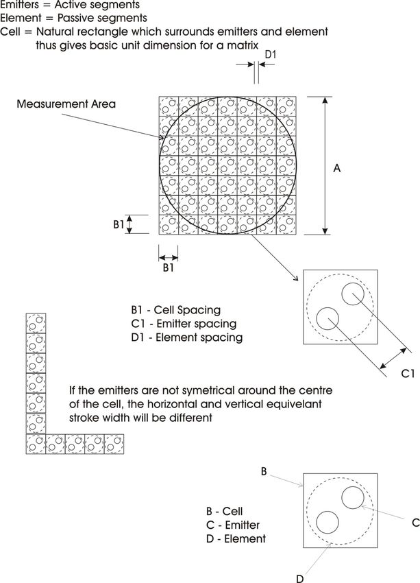
6.2.1 The pictogram display region of the sign shall be square in shape with 64 evenly spaced pixels both
horizontally and vertically.
6.2.2 The pixels shall have a height to width ratio of 1:1.
6.2.3 The overall height of the pictogram region shall be the same as the text region.
6.2.4 The pictogram display shall be capable of displaying traffic conditions for up to three destinations.
A typical display arrangement is shown in Figure 4.1.
TCS 015:2021
Page 18 of 52 Rev: A
Variable Message SignsDepartment of Transport (Roads)
6.2.5 The travel times shall be capable of displaying traffic conditions as follows:
(a) Green to indicate light traffic conditions.
(b) Yellow to indicate medium traffic conditions.
(c) Red to indicate heavy traffic conditions.
6.3 PICTOGRAM OPTICAL REQUIREMENTS
6.3.1 Optical Requirements
6.3.1.1 The optical requirements shall comply with AS 4852.1, Clause 5.2.
6.3.1.2 The photometric test procedures shall comply with AS 4852.1, Appendix C.
6.3.2 Colormetric Requirements
6.3.2.1 The colormetric requirements shall comply with AS 4852.1, Clause 5.2.4.
6.3.2.2 The colormetric test procedures shall comply with AS 4852.1, Appendix D.
6.3.3 Lifetime Performance Requirements
The lifetime performance requirements for LED pixels outputs shall be in accordance with Appendix D of this
specification.
6.4 DISPLAY CHANGES
6.4.1 The complete sign shall be capable of displaying single frames on:
• the text and pictogram regions simultaneously.
• the text region only.
• the pictogram region only.
6.4.2 The complete sign shall be capable of displaying multi-frame messages on:
• the text region only.
• the pictogram region only.
6.4.3 Where the text display region is displaying a multi-frame message, the pictogram region shall display
a static pictogram.
TCS 015:2021
Page 19 of 52 Rev: A
Variable Message SignsDepartment of Transport (Roads)
SECTION 7 OPERATION AND CONTROL
7.1 GENERAL
7.1.1 A communication link to the sign, as specified in the tender documents, shall be provided in
accordance with AS 4852.1 Section 6 and the following requirements.
7.1.2 The sign shall be capable of the following:
(a) Displaying instantaneous messages downloaded from any third-party controlling device
connected to the serial port or Ethernet port, which will temporarily override any current
displays, strings or scheduling until the instantaneous messages are completed.
(b) Displaying frames in different appearance modes.
(c) Displaying any approved font, graphic or display which fits into the given matrix, irrespective
of what pixels are on or off.
(d) Provide a list of alarms and reporting procedures.
7.1.3 This section on operation and control assumes the inclusion of the pictogram as specified in Section
6 of this specification.
7.2 SIGN CONTROL PERFORMANCE AND CAPABILITY
7.2.1 The sign shall be used for travel time information displays and the message will be updated every
two minutes. Therefore, the sign shall have the capability to support writing at least 900 messages
a day.
7.2.2 The DoT (Roads) control system uses frames numbers from 200 to 255 for displaying those
frequently updated messages.
7.2.3 The response time (the latency from when DoT (Roads) FP sends a request message to when a valid
response message is received by the FP, i.e. the response time includes the time for transferring the
request message from the FP to the sign controller via a serial link, sign controller processing time
for generating a valid response message and the time for transferring the valid response from the
sign controller to the FP via serial link) shall be less than 2 seconds.
7.3 SIGN CONTROLLER (SC)
7.3.1 The text region and the pictogram region (where required) shall each have a separate sign controller.
The pictogram section is intended to display a static message (such as travel times, roadworks
symbol, vehicle crash symbol).
7.3.2 Under normal operation, each sign controllers main purpose is to provide both serial and Ethernet
interfaces to a third-party controlling device, over which TfNSW protocol shall be transmitted in
order to control the mono-colour text region, and a 4 colour pictogram region if required, of the
connected VMS.
7.3.3 The sign controller(s) shall be designed to be installed within a standard 19’’ rack.
TCS 015:2021
Page 20 of 52 Rev: A
Variable Message SignsDepartment of Transport (Roads)
7.3.4 An alternative cabinet may be considered provided it is designed to be mounted onto the standard
VicRoads cabinet foundation.
7.3.5 The rack-mounting chassis shall be no more than 2 RU in height, and either full or half 19’’ rack
width. Half-width 19’’ modules shall be mountable on both the left and the right sides.
7.3.6 If the sign has a text and a pictogram region, the Sign Controller shall ensure:
(a) If both regions are failed, not to display any messages on either region.
(b) If the pictogram region is failed but the text region is working, continue to display the message
on the text region.
(c) If the pictogram region is working, but the text region is failed, not to display any messages on
either region.
7.3.7 All of the controller’s communication and power interfaces shall be clearly and indelibly labelled
on the controller housing.
7.4 ADMINISTRATION AND CONFIGURATION TOOL
7.4.1 The sign controller shall provide an interactive browser-based user interface using HTTP and
HTTPS to provide monitoring, configuration and diagnostic related functions.
7.4.2 Providing a Command Line Interface (CLI) based configuration interface is not mandated, however,
if provided, the interface shall:
(a) Support key-based and password authentication, with the capability to disable password
authentication
(b) SSH v2.x shall be required (SSH v1 shall not be used)
(c) Only support CLI over TCP/IP. The SC shall not have any serial-based console port on the
controller chassis, which can be used to access the SC CLI interface.
7.4.3 The software shall provide for the display and monitoring of the sign controller configuration,
including:
(a) Site Name
(b) Firmware version
(c) Current Temperature of the controller
(d) Main Power Supply status
(e) Backup Power Supply Status (if one exists)
(f) Up Time (since last reset)
(g) System time (Local date and time)
(h) MAC Address(es) of all Ethernet port(s)
(i) Current Active Control Mode (Local, serial, TCP or any other mode if present)
(j) Facility Switch position
(k) All the signs connected to the controller and, for each sign, the following information shall be
displayed:
i. TfNSW protocol Group ID
ii. TfNSW protocol Sign ID
iii. Dimensions (in pixel)
iv. Luminance dimming control mode (Auto, Time based or Fixed)
v. Current Luminance dimming level
TCS 015:2021
Page 21 of 52 Rev: A
Variable Message SignsDepartment of Transport (Roads)
vi. TfNSW Protocol Session Status (Online / Offline)
vii. TfNSW Protocol Display Mode (Message, Frame or Plan)
viii. TfNSW Protocol Display Message Number/Frame Number/Plan Number
ix. Current Sign firmware version
7.4.4 Configuration Functions – The software shall allow a user to change sign controller and sign
configurations using the browser interface. In general, all configuration changes shall be applied
immediately and take effect without the need to restart/reset the sign controller. However, changing
certain parameters may cause any currently active connection to be dropped, for example, the sign’s
password or seed offset, IP port number, etc. The following parameters shall be configurable.
(a) The Site Name – Text field with minimum 150 characters.
(b) Control Mode – The software shall allow a user to choose an active control mode from the
following:
i. Local mode – When this mode is enabled, a user can use the browser interface to
control the sign display to display a message or run test patterns. When this mode is
disabled, a user shall not be able to use this web software to control the sign display to
display a message or run test patterns.
ii. Serial – When this mode is enabled, the master (refer to TfNSW protocol section 2.1)
software can connect to sign controller via serial connection, and control the sign using
TfNSW protocol. When this mode is disabled, and there is currently an active serial
connection, the controller shall drop the connection and blank the sign(s).
When this mode is disabled and the master software attempts to connect to the sign
controller via the serial connection using TfNSW protocol, the sign controller shall
respond with a ‘Reject’ message (MI code 00h) with Application Error code ‘01’
(Device Controller offline) to the ‘Start Session’ message (MI code 02h) sent by the
master software. However, the sign controller shall still respond to ‘Heartbeat Poll’
messages (MI Code 05h) as specified in RMS Protocol Section 3.6.3.6.
(c) TCP/IP – When this mode is enabled, the master (refer to TfNSW protocol section 2.1)
software can connect to sign controller via TCP/IP connection, and control the sign using
TfNSW protocol.
When this mode is disabled, if there is currently an active TCP/IP connection, the controller
shall drop the connection and blank the sign(s). When this mode is disabled and the master
software attempts to connect to the sign controller via TCP/IP using RMS protocol, the sign
controller shall respond with a ‘Reject’ message (MI code 00h) with Application Error code
‘01’ (Device Controller offline) to the ‘Start Session’ message (MI code 02h) sent by the
master software. However, the sign controller shall still respond to ‘Heartbeat Poll’
messages (MI Code 05h) as specified in RMS Protocol Section 3.6.3.6.
Note: The control mode is exclusive. Once a mode is chosen, the other two modes shall be disabled.
7.4.5 Network configuration – The software shall allow a user to change the following network
configurations:
(a) IP address allocation (DHCP or static).
(b) If the IP address allocation is static – the following parameters: IP Address, Subnet Mask,
Default Gateway, Primary DNS and Secondary DNS.
TCS 015:2021
Page 22 of 52 Rev: A
Variable Message SignsDepartment of Transport (Roads)
7.4.6 TfNSW Protocol Configuration – The software shall allow a user to change the following TfNSW
Protocol and communications related configuration parameters:
(a) IP Port used for TCP/IP connection.
(b) Session time out for TCP/IP connection (in seconds).
(c) Security settings for TCP/IP connection (such as switch between no encryption and TLS
encrypted, TLS port to be used).
(d) Baud rate, Data bits, Parity and Stop bits for serial connection.
(e) Session time out for serial connection (in seconds).
(f) Seed offset (in Hex).
(g) Password offset (in Hex).
(h) Polling Address.
(i) Broadcast Address.
(j) Blanking Time out (in minutes, the duration that the sign controller will wait before blanking
the sign after the active RMS protocol connection is disconnected.).
(k) Sign ID and Group ID (For individual signs).
7.4.7 Luminance Dimming control – The software shall allow a user to change the following sign
dimming control related configuration for each individual sign connected to the sign controller:
(a) Luminance Dimming control mode (Auto, Time Based or Fixed). Three modes are defined in
AS 4852.1 – 2009 Section 3.11.
(b) The controller shall have pre-defined ‘Dawn’ and ‘Dusk’ times for Time Based mode as
specified in AS 4852.1 – 2009 Section 3.11 and the software shall allow a user to change those
time settings.
(c) Fixed Dimming Level (in ‘Fixed’ mode only).
7.4.8 System Time – The software shall allow a user to change the current time, time zone, Daylight
saving option and whether to use an NTP server for time synchronisation. The IP address(es) of the
NTP servers shall be configurable.
7.4.9 Security – The software shall:
(a) Allow a user to change the browser interface’s username and password.
(b) Support both HTTP and HTTPS and allow a user to choose the access mode from ‘HTTP
only’, ‘HTTPS only’ and ‘Both HTTP and HTTPS’.
(c) Allow a user to change the TCP/IP ports used for ‘HTTP’ and ‘HTTPS’.
(d) Allow a user to change the session timeout for the browser interface (duration after the last
active web request received).
7.4.10 Control and Testing – The software shall allow a user to perform local control and display test
patterns functions specified in Section 7.13 for Local Control and 7.17 for Display Test Patterns of
this specification.
7.4.11 Administration – The software shall provide the following administration functions.
TCS 015:2021
Page 23 of 52 Rev: A
Variable Message SignsDepartment of Transport (Roads)
7.4.12 Firmware upgrade
(a) The software shall allow a user to the upgrade the controller’s firmware. After the firmware is
upgraded, all existing pre-configured parameters (IP addresses, network mask, default
gateway and etc) for the controller shall be maintained.
(b) The software shall allow a user to upgrade firmware for individual signs that are connected to
the sign controller.
(c) The system shall ensure that the entire firmware file is successfully downloaded before
attempting to apply the firmware upgrade.
7.4.13 Save /recover configuration to/from file.
(a) All of the configuration parameters for the controller shall be able to be saved and retained
after rebooting the controller.
(b) The software shall allow a user to save the current configuration to a local file and be able to
restore all the configuration parameters from the file.
7.4.14 Reboot and Reset.
The software shall allow a user to reboot/reset the controller with the following options:
(a) Reset to manufacturer default.
(b) Reset to manufacturer default, except for the current network configuration (IP addresses,
network mask, default gateway, etc).
(c) Reboot the controller with all configuration maintained.
7.4.15 Reports/logs
The software shall provide separated log files, one for TfNSW protocol commands and another for
any other system logs. All the logs shall be able to be displayed via the web interface and to be
exported to text or CSV format files.
7.4.16 System event logs
The software shall log the following system events as minimum:
(a) Controller and sign fault events.
(b) TfNSW protocol connection events (only require connection and disconnection events).
(c) The login / logoff events for the browser interface software, including any failure attempts.
The parameters to be logged include the attempted usernames, passwords and source IP
addresses.
The software shall keep a minimum of the last 30 days or 5000 log entries, whichever limit comes
first. Each log shall contain a timestamp with the resolution to 1ms.
7.4.17 TfNSW command logs
The software should log every TfNSW protocol commands and response between the master
software and the controller for the last 30 days or 5000 messages. Each log shall contain:
(a) Message direction (from the master to the controller or vice versa).
(b) A timestamp with resolution to 1ms (The time the commands received or the response sent).
(c) The actually message detail in a Hex string.
TCS 015:2021
Page 24 of 52 Rev: A
Variable Message SignsDepartment of Transport (Roads)
7.4.18 Non-functional requirements
(a) Performance – The software shall respond to every user interaction less than 3 seconds
(excluding delays in the network).
(b) Security -
i. The software shall verify the username and password before granting access to the system.
ii. The software shall support both HTTP and HTTPS and allow a user to choose access mode
from ‘HTTP only’, ‘HTTPS only’ and ‘Both HTTP and HTTPS’.
iii. Only TLS shall be used for the HTTPS connection.
iv. The current VicRoads document ‘Information Security Standard: Cryptographic Controls’
shall be complied with.
v. After three successive failed login attempts, the minimum time allowed between login
attempts shall be changed to 60 seconds.
(c) Bandwidth /network requirement
The software shall be designed to run on a relatively slow IP network, such as 3G wireless network
with around 500Kbps bandwidth and 500ms latency. The user interface shall be simple to avoid
long response times. Where large amounts of information is to be displayed (such as logs), the
information shall be displayed over multiple pages with page down and page up functions.
7.5 RESET
7.5.1 On reset or reboot of the sign controller and/or VMS (regardless of source), the VMS’s display shall
be set to blank.
7.5.2 The sign controller shall incorporate a reset button accessible on the front chassis. The reset button
shall perform a soft reset the SC & Connected VMS. All configurations within the SC and VMS
shall be maintained.
7.5.3 The sign controller shall not provide any hard reset (reset the controller to manufactory default)
mechanism (such as button), which can be accessed via the chassis.
TCS 015:2021
Page 25 of 52 Rev: A
Variable Message SignsDepartment of Transport (Roads)
7.6 SIGN CONTROLLER PARAMETER DEFAULT SETTINGS
The default settings for key parameters within the SC shall be as shown in Table 7.1.
Parameter Description Default Setting
Username required for access to the SC’s Web
SC login user name ‘Admin’
based tool
Password required for access to the SC’s Web
SC login password To be provided by VicRoads.
based tool
The SC’s Site name to be displayed in the Web VicRoads allocated Site
SC Site Name
based tool Number (RAI ID)
STATIC
Selectable DHCP or statically configurable IP
SC IP address IP: 192.168.30.1
address and Netmask
Mask: 255.255.255.0
No encryption TCP: 43000
TfNSW over, TCP/IP TCP port numbers for TfNSW protocol
TLS encrypted TCP:43002
connection
Default: no encryption
Default TfNSW address TfNSW Protocol group and sign address All addresses to start from 1
RS422
Serial configuration Hardware serial settings
38400kbps, 8 N 1
TCP port number used for web access to the
HTTP: TCP 80
Web Access Ports Web based tool
HTTPS using TLS: TCP 443
Telnet TCP port number used for connection to the CLI TCP 6368
Control Mode Default controller TfNSW control mode TCP
Luminance Dimming
Default Luminance Dimming Control Mode Auto
Control Mode
Session time out for TCP/IP connection (in
TfNSW TCP Time out 300
seconds)
Session time out for serial connection (in
RTA serial Time out 180
seconds)
in minutes, the duration that the controller to
Blanking Time out black the sign after the active RTA/RMS 5
protocol connection is disconnected
in minutes, the duration that the current Web
Web Access Timeout tool connection to be after the last active web 5
request is received.
Table 7.1 – Sign controller key parameters
TCS 015:2021
Page 26 of 52 Rev: A
Variable Message SignsDepartment of Transport (Roads)
7.7 ETHERNET
7.7.1 The SC shall provide at least one 10/100 TX Ethernet interface. The Ethernet interface shall support
the modes of communication and protocols detailed in Sections 7.8, 7.9 and 7.10 of this
specification.
7.7.2 A Cat6 Ethernet cable shall be used to connect the SC to the network switch. The length of the Cat6
Ethernet cable shall not exceed 100m.
7.8 TFNSW PROTOCOL FOR SIGN CONTROL
7.8.1 The operation of the sign shall be controlled by means of the TfNSW communications protocol to
comply with AS 4852.1 Section 4.5, via the physical serial and the Ethernet interfaces defined above.
This protocol is defined in the TfNSW specification TSI-SP-003 “Communications Protocol for
Roadside Devices” current version 2.1.
7.8.2 Remote control of the sign shall be facilitated via STREAMS.
7.8.3 In order to implement the 4-colour operation of the VMS pictogram element, extensions to the
default TfNSW protocol message suite as defined by VicRoads (provided in Appendix B) will be
required. The TfNSW specification for this is ITSM-TO-ITS-CSI-002 Colour Sign Interface.
7.8.4 If a controlling device (usually a VicRoads field processor) sends an RMS command which is not
supported, then the SC shall reply with a Reject Message with an appropriate Application Error
Code as defined in the TfNSW protocol specification.
7.8.5 The sign controller shall support all fault logging and diagnostic functionality provided by the
TfNSW protocol.
7.8.6 TfNSW “Heartbeat Poll” messages from the controlling device shall be serviced by the sign
controller within 0.5 seconds of reception of the heartbeat request.
7.8.7 The sign controller may also support customised messages for special functions. In this case, such
messages shall be in TfNSW protocol format and shall be fully documented for integration with 3rd
party systems. The proposed customised messages shall be provided to VicRoads for review and
approval before implementation. The supplier shall supply full details of any such customised
TfNSW protocol messages for integration with 3rd party software vendors.
7.8.8 The sign controller shall fully implement all defined TfNSW protocol layers including error
checking as described in the TfNSW protocol specification, and with changes as described in
Appendix B of this specification.
7.9 OTHER PROTOCOLS
7.9.1 In addition to standard TCP/IP detailed above, the SC shall support the following protocols as a
minimum:
(a) ICMP (ping).
(b) NTP (to set & maintain the SC / VMS clocks).
TCS 015:2021
Page 27 of 52 Rev: A
Variable Message SignsDepartment of Transport (Roads)
Note: The SC shall set its time based on the configured NTP server or the manual input from the
admin and configuration interface. However, once the SC is connected to master software via
TfNSW protocol and if the master software uses the ‘Update Time’ command to update the SC’s
time, the SC shall use the time set by the master software until the RMS protocol session is
disconnected.
(c) HTTP (interface for admin and configuration).
(d) HTTP using TLS (secure interface for admin and configuration).
7.9.2 Where encryption is enabled, the SC shall provide a facility to securely upload encryption
certificates and/or change the encryption password from a remote location.
7.9.3 Where encryption is enabled, TLS shall be used as the encryption mechanism. TLS shall be
implemented as follows:
(a) The control system shall be the client and the sign is the server.
(b) The focus is on communication privacy and integrity, therefore, neither client nor server
authentication is required.
(c) The sign controller shall be able to have a TLS certificate (with private key) uploaded to be
used as a server certificate, to be used in the negotiation of a secure TLS/SSL connection.
(d) The sign controller shall perform as a TLS server endpoint and does not need to authenticate
the client.
(e) TLS v1.2 shall be supported.
7.10 HARDWARE SERIAL PORTS:
7.10.1 The SC shall provide a minimum of two hardware serial ports with standard DB-9 connectors. Each
of the ports shall correspond to the text and pictogram elements respectively and shall provide
control of these sign elements using TfNSW protocol.
7.10.2 Both of the serial ports shall function in accordance with Table 7.2:
Physical Interface Std. RS422 and RS485
(autosensing, or software configurable)
Baud Rate 38400bps – 115200bps
Data bits / stop bits Configurable
Parity Configurable
Table 7.2 – Serial port function
TCS 015:2021
Page 28 of 52 Rev: A
Variable Message SignsYou can also read