Using the AirLink RV50X - with LI-COR Eddy Covariance and Soil Gas Flux Systems Instruction Manual
←
→
Page content transcription
If your browser does not render page correctly, please read the page content below
Using the
AirLink RV50X
with LI-COR Eddy Covariance
and Soil Gas Flux Systems
Instruction Manual
Using the AirLink RV50X
                                            with LI-COR Eddy Covariance
                                               and Soil Gas Flux Systems

LI-COR Biosciences
4647 Superior Street
Lincoln, Nebraska 68504
Phone: +1-402-467-3576
Toll free: 800-447-3576 (U.S. and Canada)
envsales@licor.com

Regional Offices

LI-COR Biosciences GmbH
Siemensstraße 25A
61352 Bad Homburg
Germany
Phone: +49 (0) 6172 17 17 771
envsales-gmbh@licor.com

LI-COR Biosciences UK Ltd.
St. John’s Innovation Centre
Cowley Road
Cambridge
CB4 0WS
United Kingdom
Phone: +44 (0) 1223 422102
envsales-UK@licor.com

LI-COR Distributor Network:
www.licor.com/env/distributors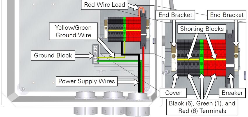
NOTICE
The information contained in this document is subject to change without notice.
LI-COR MAKES NO WARRANTY OF ANY KIND WITH REGARD TO THE THIS MATERIAL, INCLUDING, BUT NOT
LIMITED TO THE IMPLIED WARRANTIES OF MERCHANTABILITY AND FITNESS FOR A PARTICULAR PURPOSE.
LI-COR shall not be liable for errors contained herein or for incidental or consequential damages in connection with the
furnishing, performance, or use of this material.
Sierra Wireless™, ACEmanager™, and AirLink® are trademarks of Sierra Wireless. Laird is a registered trademark of
Laird Technologies®, Inc. AT&T® is a registered trademark of AT&T Intellectual Property. Rogers™ is a trademark of
Rogers Communication Inc. Internet Explorer® is a registered trademark of Microsoft® Corporation. Firefox® is a
registered trademark of The Mozilla® Foundation. Chrome® browser is a registered trademark of Google™, Inc. All
other trademarks or registered trademarks are property of their respective owners.
New editions of this manual will include all updates. An update addendum may be used between editions to provide up-
to-date information. Revisions are indicated by the version number. Minor updates that do not alter the meaning of the
content will be incorporated without affecting the version number.

Printing History
Copyright © 2020, LI-COR, Inc. All rights reserved.
Publication Number: 984-17122 Rev 3
Created on: Tuesday, September 29, 2020
This document contains proprietary information which is protected by copyright. All rights are reserved. No part of this
document may be may be reproduced or translated into another language with prior written consent of LI-COR, Inc.

                                                            ii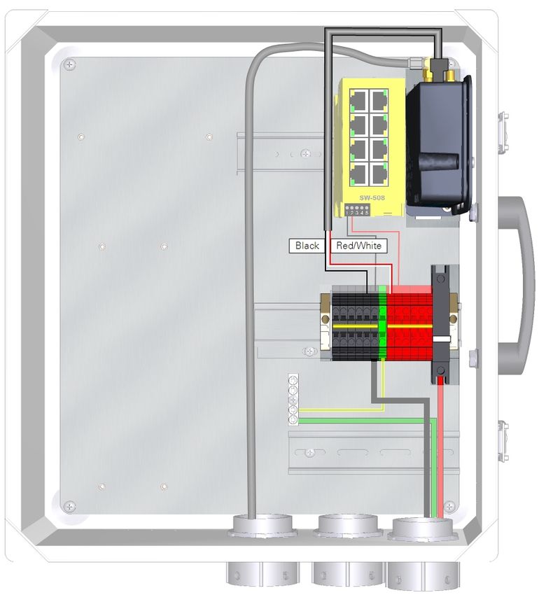
Notes on Safety
This LI-COR product has been designed to be safe when operated in the manner described in this manual. The safety of
this product cannot be assured if the product is used in any other way than is specified in this manual. The product is
intended to be used by qualified personnel. Read this entire manual before using the product.

 Equipment markings:

                  The product is marked with this symbol when it is necessary for you to refer to the manual or
                  accompanying documents in order to protect against injury or damage to the product.
                  The product is marked with this symbol when a hazardous voltage may be present.

                  The product is marked with this symbol if a Chassis Ground connection is required.

                  The product is marked with this symbol to indicate that a direct current (DC) power supply is
                  required.
   WARNING        Warnings must be followed carefully to avoid bodily injury.
   CAUTION        Cautions must be observed to avoid damage to your equipment.
 Manual markings:

   Warning        Warnings must be followed carefully to avoid bodily injury.
   Caution        Cautions must be observed to avoid damage to your equipment.
   Note           Notes contain important information and useful tips on the operation of your equipment.

 Note: Read and comply with all instructions provided by the manufacturers prior to using the wireless gateway or
 router, satellite modem, network switch, and antennas.

CE Marking:
This product is a CE-marked product. For conformity information, contact LI-COR Support at envsupport@licor.com.
Outside of the U.S., contact your local sales office or distributor.

                                                           iii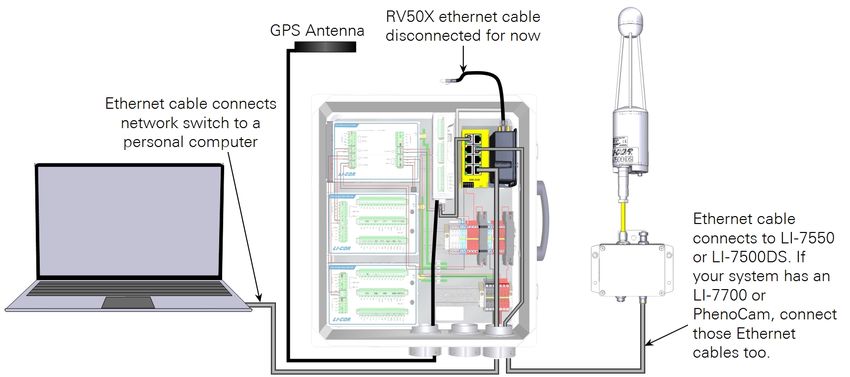
iv
Contents

Section 1. Introduction to the communication system
Arranging a data plan                                     1-1
What's what                                               1-2
Overview of the RV50X                                     1-2
    Cable connections                                     1-2
    Power connector                                       1-3
    Product labels                                        1-3
    Indicator LEDs                                        1-4
Optional accessories                                      1-6
    Pre-configured biomet system enclosure                1-6
    Eddy covariance system enclosure                      1-6
    Power distribution kit                                1-7
    35 mm DIN rail                                        1-7

Section 2. Initial assembly
Preparing the enclosure                                   2-1
Installing the SIM card                                   2-3
Attaching the mounting bracket                            2-3
Connecting cables to the RV50X                            2-4
Mounting the RV50X in the enclosure                       2-5
    Connecting power wires                                2-6
    Connecting network cables                             2-7
Connecting the antenna                                    2-8
Installing the antenna in the field                       2-8
Securing cables                                           2-9

Section 3. Configuring instrument IP addresses
Power on the system                                       3-1
Configuring the instrument network                        3-2
    Setting the LI-7700 IP address                        3-2
    Setting the PhenoCam IP address                       3-4
    Setting the LI-8100A IP address                       3-5
    Setting the LI-7500A/RS/DS or LI-7200/RS IP address   3-6
    Identifying the SmartFlux 2 System MAC address        3-7

                                                     v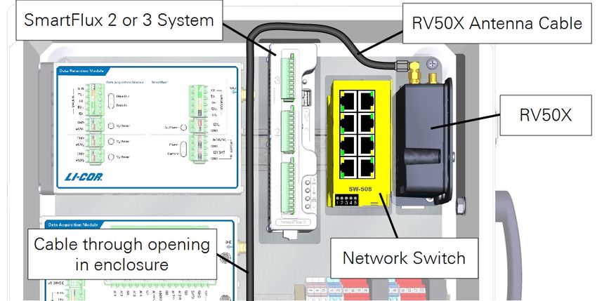
Section 4. Configuring the RV50X
Connect the RV50X Ethernet cable to the switch                                                                 4-1
Logging in to ACEmanager™                                                                                      4-2
Configuring the access point name                                                                              4-2
Viewing the RV50X IP address                                                                                   4-4
Reserving an IP address range                                                                                  4-4
Configuring port filtering                                                                                     4-5
Enabling port forwarding                                                                                       4-6
   For   the   LI-7500A/RS/DS or LI-7200/RS and file transfer utility                                          4-7
   For   the   LI-7700                                                                                         4-8
   For   the   Biomet Data Acquisition System                                                                  4-9
   For   the   PhenoCam                                                                                       4-12
   For   the   LI-8100A system                                                                                4-13
   For   the   Biomet System (Sutron datalogger)                                                              4-14
Enabling remote access to the RV50X                                                                           4-15
Applying settings and restarting the RV50X                                                                    4-15

Section 5. Connecting with remote instruments
Connecting to the LI-7500A/RS/DS or LI-7200/RS system                                                          5-1
Eddy covariance file management and data transfer                                                              5-2
Connecting to the LI-7700                                                                                      5-5
Connecting to a LI-COR Biomet Data Acquisition System                                                          5-6
Connecting to the PhenoCam                                                                                     5-6
Connecting to the biomet system (Sutron logger)                                                                5-6
Connecting to the LI-8100A system                                                                              5-8
LI-8100A data management and file transfer                                                                     5-8

Section 6. Troubleshooting
Power on problems                                                                                              6-1
Cannot connect to RV50X using ACEmanager                                                                       6-1
Cell reception is poor (>-110 dBm)                                                                             6-2
Connection problems                                                                                            6-2
   I can connect to the internet through the RV50X, but I can't connect to my instruments over the internet    6-2
   I can connect to the RV50X over the internet, but I can't connect to some instruments                       6-2

Section 7. Maintenance

                                                           vi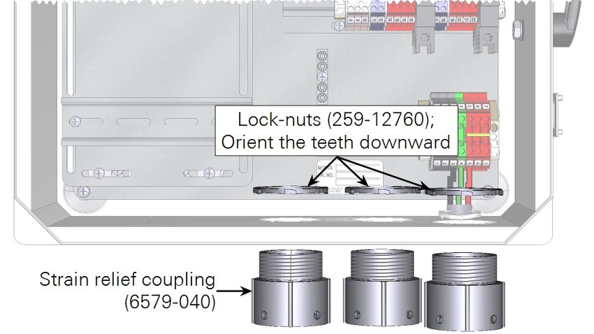
Appendix A. Additional considerations
Selecting a data plan                              A-1
About sensor networks                              A-2
One-way or two-way communication with the RV50X    A-4
    One-way communication                          A-4
    Two-way communication                          A-4
About the SmartFlux 2 System IP address            A-7
    For the NTP server                             A-7
    For file transfer functions                    A-7
Changing the RV50X password                        A-8
Configure PC network communication                 A-9
Setting the Sutron Datalogger IP address          A-11

Appendix B. Specifications

Appendix C. Warranty

Appendix D. Index

                                            vii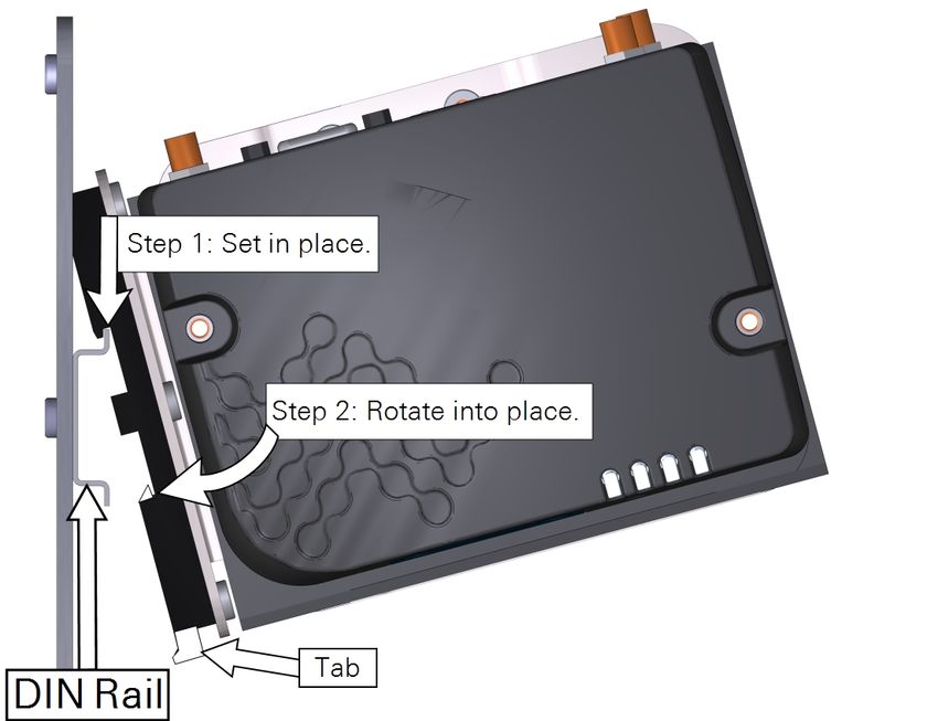
viii
Section 1.
Introduction to the communication system
                  The cellular communication system enables wireless communication with LI-COR
                  eddy covariance systems and soil gas flux systems over cellular networks. The sys-
                  tem includes a Sierra Wireless AirLink RV50X cellular modem that supports 4G
                  LTE with fallback to HSPA+ protocols. The RV50X requires a service agreement
                  with a cellular provider.
                  Two models of RV50X are available to support global cellular networks. These are
                  made available from LI-COR as package 7900-715 and 7900-716 (see Table 1-1
                  below). Both packages include all of the hardware required to use the cellular com-
                  munication system with LI-COR eddy covariance and soil gas flux systems.

                  Table 1-1. LI-COR cellular communication packages and regions supported.
                   Part Number    Region
                   7900-715       North America, South America, Europe, Middle East, Africa (NA, SA,
                                  EMEA)
                   7900-716       Asia Pacific (APAC)

Arranging a data plan
                  Prior to using the RV50X you need to arrange a data plan with a wireless service
                  provider that offers cellular coverage at your site. The cellular service should be
                  3G/4G and be compatible with the frequencies and bands supported by the modem.
                  Obtain public fixed IP address. If you have access to a corporate or institutional cel-
                  lular account, you may need to arrange a payment plan within your institution. See
                  Selecting a data plan on page A-1.
                  Typically, the service provider will issue a SIM card (mini SIM, 2FF) that must be
                  installed in the modem see Introduction to the communication system above). They

AirLink Cellular Communication                                                                         1-1
Section 1. Introduction to the communication system
will also provide a telephone number, IP Address, and Access Point Name (APN)
that are associated with the SIM card.
What's what
If you have just taken delivery of the communication system, check the packaging
list to verify that you received everything ordered. The system will include an
RV50X, power cable, data cable, antenna, antenna cable, and mounting hardware.
Table 1-2. Communication system components.
Description Qty. Part Number
Sierra Wireless AirLink RV50X Cellular Modem 1
RV50X; NA, SA, EMEA (included with 7900-715) - 616-18846
RV50X; APAC (included with 7900-716) - 616-18847
Power Cable 1
90° Right-angle Coaxial Antenna Cable Adapter 1 312-13913
4.6 m Coaxial Antenna Cable 1 380-13839
Laird Technologies High-Gain Cellular Antenna 1 609-13832
Antenna Mounting Hardware -
1.5 m Antenna Mounting Post 1 9879-064
Ethernet Cables
30 cm Standard Ethernet Cable 1 616-16844
2.1 m Standard Ethernet Cable 1 616-06116
5 m Ethernet Cable (8-pin Turck to RJ-45) Optional 392-13977
25 m Ethernet Cable (8-pin Turck to RJ-45) Optional 392-16699
50 m Ethernet Cable (8-pin Turck to RJ-45) Optional 392-13767
Overview of the RV50X
An RV50X Quick Start Guide is included in the device. Full documentation is avail-
able from Sierra Wireless: (https://source.sierrawireless.com/devices/rv-series/rv50x/).
Cable connections
The cable connectors that are used in this application are labeled below.
1-2 AirLink Cellular CommunicationSection 1. Introduction to the communication system
Power connector
In the power cable, the red and white wires must be twisted together and connect to a
positive (+) 9 to 36 VDC power supply. The black wire goes to the negative (-). The
green wire is not used.
Product labels
You may need certain details about your RV50X, such as the IMEI Number when
configuring the data plan. This information is given on the label on the bottom of
the RV50X and the packaging box. For devices that support unique passwords, the
default password is printed on the device label. For other devices, the default pass-
word is 12345.
Power connector 1-3Section 1. Introduction to the communication system
Indicator LEDs
The RV50X indicator panel has four LED lights to indicate the status.
All LEDs
l Green LED chase: Radio module reconfiguration/firmware update or Network
Operator Switching is in progress.
l Amber LED chase: ALEOS software update is in progress.
l Solid Amber: ALEOS software update complete (all LEDs are amber except the
Power LED)
l Red LED chase: The RV50X is in Recovery mode.
Network LED
Indicates the status of the network connection.
l Solid Green: Connected to an LTE network. Off when in LED power saving
mode.
l Solid Amber: Connected to a 3G network. Off when in LED power saving
mode.
l Flashing Green: Connecting to a network.
l Flashing Red: No network available.
l Flashing Red/Amber: Network Operator Switching is enabled. Consult the
RV50X documentation for details.
Signal LED
Indicates the cellular signal strength.
l Solid Green: Good signal; equal to about 4 or 5 bars.
l Solid Amber: Fair signal; equal to about 2 or 3 bars.
1-4 AirLink Cellular CommunicationSection 1. Introduction to the communication system
l Flashing Amber: Poor signal; equal to about 1 bar. Relocate the antenna in an
attempt to improve the signal strength.
l Flashing Red: Insufficient signal. Relocate the antenna in an attempt to
improve the signal strength.
Activity LED
Indicates data transfer over the cellular network.
l Flashing Green: Data is being transmitted or received over the WAN interface.
This behavior only appears if the RV50X is configured to display it.
l Flashing Red: Data is being transmitted or received over the RS-232 Serial con-
nection. This behavior only appears if the RV50X is configured to display it.
l Flashing Amber: Data is being transmitted or received over both the WAN inter-
face and the serial connection.
Power LED
Indicates the input power.
l Off: No power or input voltage is ≥36 VDC or ≤7 VDC.
l Solid Green: Power is present.
l Green with Amber Flash: Power is present and the RV50X has a GPS fix.
l Solid Red: Standby mode.
l Flashing Green: When you press the reset button, flashing green indicates
when to release the reset button to reboot the RV50X.
l Flashing Red: When you press the reset button, flashing red indicates when to
release the reset button to reset the RV50X to the factory default settings.
l Flashing Amber: When you press the reset button for more than 20 seconds,
flashing amber indicates when to release the reset button to enter Recovery
mode. Consult the RV50X documentation for details.
Indicator LEDs 1-5Section 1. Introduction to the communication system
Optional accessories
The following accessories are available to support the communication system.
Pre-configured biomet system enclosure
Part Number: The pre-configured enclosure is a large weather resistant box with mounting hard-
7900-126 ware. It is set up for the LI-COR Biomet Data Acquisition System and other
accessories. It includes all of the terminal connections and DIN rails required for a
complete eddy covariance system.
Table 1-3. Components included with the enclosure. Many of these parts are
installed in the enclosure prior to delivery.
Component Qty. Part Number
10-amp Circuit Breaker; DIN Mountable 2 275-13499
Red 1-tier Terminals; DIN Mountable 8 331-12822
Gray 2-tier Terminals; DIN Mountable 3 331-12885
Blue 2-tier Terminals; DIN Mountable 4 331-12959
Red 4 mm Terminals; DIN Mountable 3 331-13508
Green 4 mm Terminal; DIN Mountable 1 331-13510
Black 4 mm Terminals; DIN Mountable 3 331-13511
4-position Shorting Blocks 2 331-17204
3-position Shorting Blocks; 4 mm 2 331-16821
2-position Shorting Blocks 2 331-13646
DIN Terminal Covers 5 331-12825
DIN End Bracket 4 331-12922
DIN Terminal Labels 2 331-12934
Adhesive Cable Tie Mounts 5 218-03683
Phillips Pan Head Screw (10-32; 3/8") 4 122-00072
Risers to mount the battery 2 9879-090
Riser Plate 1 9879-091
Raised Terminal Block and DIN Mount 1 6579-078
DIN Rail (14 cm) 4 6579-079
Eddy covariance system enclosure
Part Number: A basic enclosure with a minimal set of internal components. Includes a pre-drilled
7900-050 internal back plate, three DIN rails for mounting components, and three strain
relief fittings. It is best to pair this with the Power Distribution Kit (7900-235).
1-6 AirLink Cellular CommunicationSection 1. Introduction to the communication system
Power distribution kit
Part Number: Includes DIN-mountable terminal connections, shorting blocks, and a 10-amp cir-
7900-235 cuit breaker. Provides 11 individual positive and negative power terminals for the
system. Installs in the 7900-050 eddy covariance system enclosure.
Description Quantity Part Number
10-amp Circuit Breaker; DIN Mountable 1 275-13499
DIN Terminal Cover 1 331-12825
DIN Terminal End Bracket 2 331-12922
Red 4 mm Terminals; DIN Mountable 6 331-13508
Green 4 mm Terminals; DIN Mountable 1 331-13510
Black 4 mm Terminals; DIN Mountable 6 331-13511
6-position Shorting Box 2 331-13512
14 AWG Red Wire Lead 1 392-13829
18 AWG Green/Yellow Ground Wire Lead 1 372-04621
35 mm DIN rail
Part Number: Optional DIN rail to mount additional hardware in the eddy covariance system
6579-023 enclosure.
Power distribution kit 1-7Section 1. Introduction to the communication system 1-8 AirLink Cellular Communication
Section 2.
Initial assembly
                  This section describes how to assemble and deploy the communication system. The
                  following tools are required:

                   l   Phillips and Standard slotted screwdrivers
                   l   Bolt drivers or wrenches: 16 mm, 13 mm, and 8 mm (5/8", 1/8", and 5/16"
                       approximate SAE equivalents)
                   l   Post driver for antenna post

                  The hardware installation will take about 30 to 60 minutes. Software configuration
                  will take about 30 minutes to 2 hours.

                    Note: We recommend that you fully assemble the system, configure your data
                    plan, and test the system in your office or lab before deploying it in the field.
                    Allow ample time to troubleshoot any issues and to verify that everything is work-
                    ing as expected to avoid having to make unplanned site visits.

Preparing the enclosure
                  In both the eddy covariance system enclosure (7900-050) and the Biomet Data
                  Acquisition System enclosure (7900-126), install the three strain-relief couplings in
                  the three bottom openings.

AirLink Cellular Communication                                                                      2-1
Section 2. Initial assembly
In the eddy covariance system enclosure (7900-050), install the Power Distribution
Kit (7900-235) on the raised DIN rail. Connect the red wire lead between the top of
the breaker and top right red terminal. Install one shorting block to connect all
black terminals and another to connect all red terminals.
Figure 2-1. The power distribution kit (7900-235) installed in the enclosure (7900-050).
2-2 AirLink Cellular CommunicationSection 2. Initial assembly
Installing the SIM card
The SIM card installs in the upper slot. The upper slot is the primary slot; do not
install the card in the lower slot unless you have both primary and backup cards.
Press it in until the card clicks in place, the reinstall the cover.
Attaching the mounting bracket
Attach the mounting bracket and connect the DIN rail clip.
Installing the SIM card 2-3Section 2. Initial assembly
Connecting cables to the RV50X
Connect the 30 cm Ethernet cable and power cable to the RV50X. Connect the 90°
elbow to the connector labeled Cellular . Connect the antenna cable to the elbow.
2-4 AirLink Cellular CommunicationSection 2. Initial assembly
Mounting the RV50X in the enclosure
Install the RV50X on the DIN rail. Set the top in place, and then rotate until the
lower part clips to the lower rail. Pull the white tab to release the clip.
Mounting the RV50X in the enclosure 2-5Section 2. Initial assembly
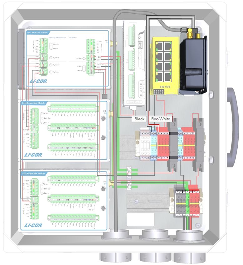
Connecting power wires
Note: Do not power on the RV50X yet. Leave the breakers OFF until later in the
process (see Power on the system on page 3-1).
Cut the power cable to a suitable length (30 to 50 cm) and carefully remove about
5 cm (2") of outer insulation. Strip about 1.3 cm (½") of insulation from the black,
red, and white wires. Twist the red and white wires together. The green wire is not
used. Connect the wire leads to suitable power terminals in the enclosure.
Table 2-1. RV50X power wire connections for the Biomet Data Acquisition System
enclosure or the eddy covariance system enclosure.
From Wire Color To
DIN Terminal 11 (top) or Black DIN Terminal black RV50X Ground (-)
DIN Terminal 13 (top) or Red DIN Terminal red and white RV50X Power (+)
2-6 AirLink Cellular CommunicationSection 2. Initial assembly
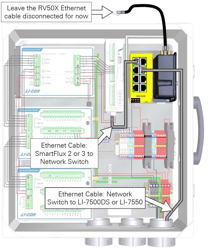
Connecting network cables
Important: Do not connect the RV50X Ethernet cable to the switch yet. Leave it
disconnected until all of the instruments are configured.
Install an Ethernet cable between the LI-7550 or LI-7500DS and the switch; and the
SmartFlux System and the switch. Leave the 30-cm Ethernet cable (part number
616-16844) from the RV50X disconnected for now.
Connecting network cables 2-7Section 2. Initial assembly
Connecting the antenna
Warning: Maintain at least 20 cm separation distance between the antenna and
your body when the RV50X is powered on.
The antenna cable is a slender coaxial cable that attaches to Cellular terminal on the
RV50X. The other end connects to the terminal on the bottom of the antenna.
Tighten the cable connections securely.
Note: When closing the enclosure, carefully fold over any cables and secure
them in the box. Use caution to ensure that the cables are not bent sharply or
pinched by the lid.
Installing the antenna in the field
Important: The antenna is a transmitter-receiver that broadcasts electromagnetic
radio signals. Some electronic devices, data recorders, and sensors may be sus-
ceptible to radio interference from this antenna. Therefore, it is important to pos-
ition the antenna at a reasonable distance from sensors and data recorders. Never
put the antenna in an instrument enclosure, adjacent to instruments on your
instrument platform, or pointing toward instruments or cables. Maximize the dis-
tance between instruments and the antenna using the provided 4.6 m cable to
reduce the chance of radio interference.
Position the antenna so that it has clear reception and does not interfere with the
variables you are measuring. Be sure it does not shadow any radiation sensors,
obstruct the rain gauge, or obstruct eddies in an eddy covariance system.
1 Before you dig!
Check to ensure that there are no underground gas lines, electrical lines, or unex-
ploded ordnance in the vicinity.
2 Drive the antenna mounting post.
Drive the post at least 50 cm into the ground and attach the antenna using the
included bracket and band clamp. In sandy, muddy, or loose soils additional sup-
port may be required to secure the mounting post.
2-8 AirLink Cellular CommunicationSection 2. Initial assembly
Figure 2-2. Antenna mounting configuration. Drive the post at least 50 cm into the ground
or more in sandy, loose, or muddy soil.
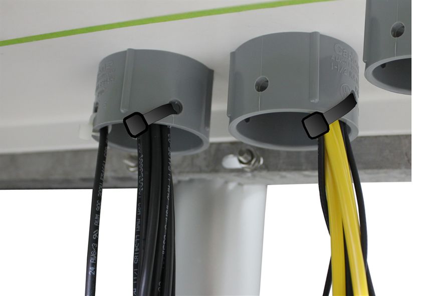
Securing cables
Communication and power cables
should be secured so they do not apply
strain to connectors and junctions.
Secure the cables to the strain-relief
plugs as shown.
Securing cables 2-9Section 2. Initial assembly 2-10 AirLink Cellular Communication
Section 3.
Configuring instrument IP addresses
                  The objective of this section is to configure the network settings of the instruments,
                  including the LI-7500A/RS/DS, LI-7200/RS, LI-7700, and LI-8100A. You'll need to
                  do this for each instrument to enable communication through the network con-
                  nection. If you are using a biomet system with a Sutron Datalogger, also see Setting
                  the Sutron Datalogger IP address on page A-11.

Power on the system
                    Note: Disconnect the RV50X Ethernet cable for this section.

                  Double check the power wiring and data cable connections. Flip both breakers to
                  the ON position and wait a few minutes for everything to start up.

                  Figure 3-1. Connecting to the system with a PC. At this point, the RV50X Ethernet cable is
                  still unplugged but the system can be powered on.

AirLink Cellular Communication                                                                          3-1
Section 3. Configuring instrument IP addresses
Configuring the instrument network
Go through the following pages to configure IP addresses for each component.
Skip any sections that don't apply to you until you get to Setting the LI-7500A/RS/DS
or LI-7200/RS IP address on page 3-6.
Table 3-1. Suggested IP addresses for instruments in an eddy covariance system.
Sensor Suggested IP Address
SmartFlux 2 System1 192.168.13.200
LI-7200/RS or LI-7500A/RS/DS 192.168.13.201
LI-7700 192.168.13.202
LI-8100A 192.168.13.203
Biomet System (Sutron Datalogger) 192.168.13.204
PhenoCam 192.168.13.205
Setting the LI-7700 IP address
If your system includes an LI-7700, start by configuring its IP address. If you do not
have an LI-7700, skip to the next section.
1 Launch the LI-7700 software and connect to the instrument.
1Required only to enable the NTP (network time protocol) and two-way communication with a Biomet
Data Acquisition System connected to the SmartFlux 2 System.
3-2 AirLink Cellular CommunicationSection 3. Configuring instrument IP addresses
2 Click the Manual Controls button.
3 Set the IP Address, Netmask, and Gateway.
l IP Address: 192.168.13.202
l Subnet Mask: Typically 255.255.255.0
l Gateway: Set this to the IP address used to connect with the RV50X:
(192.168.13.31)
Reboot the LI-7700 after changing the network settings.
Setting the LI-7700 IP address 3-3Section 3. Configuring instrument IP addresses
Setting the PhenoCam IP address
If your system includes a PhenoCam, set its IP address next.
1 Be sure the camera is powered on and the Ethernet cable is connected to the switch.
2 Launch the StarDot Tools application.
Download it from http://www.stardot.com/downloads and install it on your Win-
dows computer. Launch the app and it will present all of the PhenoCams that are
on your network. Identify the one you want to configure and record its ID and IP
address.
3 Enter the IP Address into a web browser address bar.
Upon connecting, the browser will display a recent image from the camera as well
as some menu links.
4 Click Config in the lower left of the page and log in when prompted.
l User Name: admin
l Password: admin
5 Click the Network tab and configure the settings:
A Under IP Assignment, select Manual.
B Set the IP Address:
l IP Address: 192.168.13.205
l Subnet Mask: Typically it should be 255.255.255.0
l Gateway: Set this to the IP address used to connect with the RV50X:
(192.168.13.31)
Reboot the PhenoCam after changing the network settings.
3-4 AirLink Cellular CommunicationSection 3. Configuring instrument IP addresses
Setting the LI-8100A IP address
If your system includes an LI-8100A, set its IP address next.
1 Connect a PC to the LI-8100A using the RS-232 cable.
2 Launch the LI-8100A PC software and connect with the instrument.
3 Click 8100 > Networking... and enter an IP Address, Netmask, and Gateway.
l IP Address: 192.168.13.203
l Subnet Mask: Typically it should be 255.255.255.0
l Gateway: Set this to the IP address used to connect with the RV50X:
(192.168.13.31)
4 Restart the LI-8100A after changing the network configuration.
If you are using a stand-alone RV50X, connect the LI-8100A network cable to the
RV50X and keep the RS-232 cable in place for the remaining configuration. If you
Setting the LI-8100A IP address 3-5Section 3. Configuring instrument IP addresses
are using the LI-8100A in an eddy covariance station, connect the LI-8100A to the
network switch.
Setting the LI-7500A/RS/DS or LI-7200/RS IP address
The LI-7500A/RS/DS or LI-7200/RS, in combination with the SmartFlux 2 or 3 Sys-
tem is the hub of the eddy covariance system.
1 Launch the gas analyzer software.
Select the gas analyzer and Connect to it.
2 Stop data logging.
Click the Stop button on the software dashboard.
3 Configure the LI-7500A/RS/DS or LI-7200/RS for a Static IP Address: Click Settings > Network
and enter the IP Address, Subnet Mask, and Default Gateway.
l IP Address: 192.168.13.201
l Subnet Mask: Typically 255.255.255.0
l Default Gateway: Set this to the local IP address of the RV50X (192.168.13.31).
3-6 AirLink Cellular CommunicationSection 3. Configuring instrument IP addresses
4 Reboot the instrument after changing the network settings.
Identifying the SmartFlux 2 System MAC address
This step is required only if you want to use the SmartFlux 2 System as an
NTP server or to enable two-way communication with the Biomet Data Acquisition
System that is connected to a SmartFlux 2 System (to upload a new configuration
file to a DAqM or DRM, for example). To find the SmartFlux 2 System MAC
address, click the SmartFlux button and select the SmartFlux Connection tab. Copy
the MAC Address or keep the window open so you can find it later when you'll
enter it into the RV50X software.
Now you are ready to configure the RV50X. See Configuring the RV50X on page 4-1.
Identifying the SmartFlux 2 System MAC address 3-7Section 3. Configuring instrument IP addresses 3-8 AirLink Cellular Communication
Section 4.
Configuring the RV50X
Prior to using the communication modules, you have a data plan with a service pro-
vider (see Arranging a data plan on page 1-1).
Note: Sometimes networked cellular devices take a few minutes to finish booting
and to establish communications. If the devices seem unresponsive, wait a few
minutes and try again before you give up.
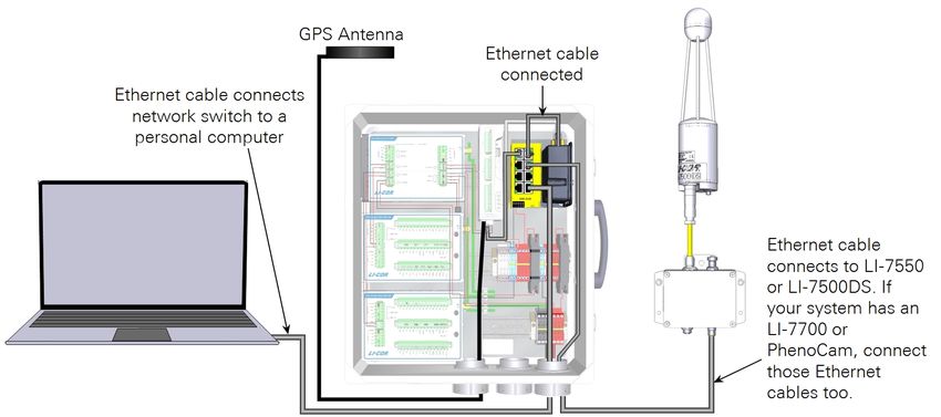
Connect the RV50X Ethernet cable to the switch
At this point in the setup, everything should be powered on. Connect the RV50X
Ethernet cable to the network switch then proceed through the steps in this sec-
tion.
AirLink Cellular Communication 4-1Section 4. Configuring the RV50X
Logging in to ACEmanager™
If you have trouble connecting to ACEmanager™, refresh the window (press F5) or
try a different web browser. Firefox, Google Chrome, and Microsoft Edge all seem
to work well.
1 Open an internet browser and enter: http://192.168.13.31:9191 in the address bar.
This will connect to the RV50X with the ACEmanager™ interface.
2 Enter the default user name and password. The user name is user .
For devices that support unique passwords, the default password is printed on the
device label. For other devices, the default password is 12345.
IMPORTANT: To protect your data and system from digital security threats, it is
important to change the password. See Changing the RV50X password on page A-8.
In addition, check the Sierra Wireless website for product information. Update
the embedded software any time updates are available.
Configuring the access point name
Your service provider will provide you with an Access Point Name (APN) when
you sign up for cellular service. If not, you may need to contact the provider and
request the APN associated with your wireless account. The APN will either be con-
figured automatically or it must be entered manually. To check and configure the
APN:
1 Log into ACEmanager (see Logging in to ACEmanager™ above).
2 Check the IP address.
Under Status > Cellular , the IP Address field will show the IP address. If it is 0.0.0.0
or anything other than your assigned IP address, follow these steps to set the APN.
4-2 AirLink Cellular CommunicationSection 4. Configuring the RV50X
3 Click the WAN/Cellular tab.
If you installed the card in slot 1 (see Installing the SIM card on page 2-3), select SIM
Slot 1. The APN assigned by the service provider may already be shown beside APN
In Use. If it is not, enter your assigned APN beside User Entered APN.
If the service provider also requires network authentication, on the same page,
under Advanced, enter information for Network Authentication Mode, Network
user ID, and Network Password.
4 Click Apply.
When prompted, Restart the device and log in again.
5 Repeat step 2 above and check the IP Address.
Look for your assigned IP address. It will be a numeric string of four octets (groups
of three-digit numbers >0 andSection 4. Configuring the RV50X
Viewing the RV50X IP address
You must know the RV50X IP address in order to connect with the system and any
connected device. The RV50X will have either a public Static IP address (recom-
mended) or a public Dynamic IP address (see One-way or two-way communication
with the RV50X on page A-4 for more information).
When your computer is connected to the RV50X and you are logged in, you can
view the RV50X IP Address under Status > Home > Active WAN IP Address.
Reserving an IP address range
It is useful to have an IP address range reserved so do not have to alter your com-
puter's network settings when connecting. In doing so, you will be able to connect
a computer that is configured for a dynamic IP address (assumed to be the com-
mon default setting) to the RV50X. It will be assigned an IP address by the RV50X
when connecting.
The range of 192.168.13.100 to 192.168.13.150 will work for the applications
described here. This range should not encompass the IP addresses assigned to
instruments.
4-4 AirLink Cellular CommunicationSection 4. Configuring the RV50X
Configuring port filtering
Inbound Port Filtering can protect the instruments at the site from nefarious hack-
ing attempts over the network. For this reason we recommend blocking port 22, as
described below.
1 In ACEmanager, click Security > Port Filtering - Inbound.
2 For Inbound Port Filtering Mode, choose Blocked Ports.
3 Click Add More and set Start Port to 22 and End Port to 22.
Configuring port filtering 4-5Section 4. Configuring the RV50X
Enabling port forwarding
Port forwarding allows remote computers and devices to connect to a specific
device within a Local Area Network. Port forwarding must be enabled in the
RV50X software to allow you to communicate with the devices that are connected
to it (such as an LI-7500DS or other instrument).
1 In ACEmanager, click Security > Port Forwarding.
2 Set Port Forwarding to Enable.
3 Click Apply or wait until you've finished configuring port forwarding for instruments.
You do not need to click apply and reboot immediately; you have additional
changes to make. But port forwarding does not take effect until the device is
rebooted. Wait to restart until you've finished the remaining configuration.
4-6 AirLink Cellular CommunicationSection 4. Configuring the RV50X
For the LI-7500A/RS/DS or LI-7200/RS and file transfer utility
This procedure configures ports for the LI-7500A/RS or LI-7200/RS (with the
SmartFlux 2 System), or the SmartFlux 3 System (with the LI-7500DS). It also
opens a port for the file transfer utility, which makes it possible to copy data files
from the device. In ACEmanager™, under Security > Port Forwarding, click Add
More and enter the information.
Add port 7200 for the gas analyzerfile transfer utility are 7200 and 22.
If using the SmartFlux 2 System (not SmartFlux 3), open an additional port to
allow files to be copied from the LI-7550 USB drive.
Table 4-1. Ports for the LI-7500A/RS or LI-7200/RS and SmartFlux 2 System, the
LI-7500DS and SmartFlux 2 System, and the file transfer utility used by both.
Public Start Port Public End Port Protocol Host IP Private Start Port
7200 0 TCP 192.168.13.201 7200
7222 0 TCP 192.168.13.201 22
52221 0 TCP 192.168.13.200 22
1Used only to make it possible to copy files from the SmartFlux 2 System USB drive. Not required for the
SmartFlux 3 System.
For the LI-7500A/RS/DS or LI-7200/RS and file transfer utility 4-7Section 4. Configuring the RV50X
For the LI-7700
If the system includes an LI-7700, click Add More and enter the highlighted
information below.
Public Start Port Public End Port Protocol Host IP Private Start Port
7200 0 TCP 192.168.13.201 7200
7222 0 TCP 192.168.13.201 22
7700 0 TCP 192.168.13.202 7700
4-8 AirLink Cellular CommunicationSection 4. Configuring the RV50X
For the Biomet Data Acquisition System
If the system includes a LI-COR Biomet Data Acquisition System, you do not need
to open ports in order to log data. However, to enable two-way communication (to
update the biomet system configuration remotely, for example) or to use the
SmartFlux 2 or 3 System as an NTP server, you must also open three ports. Port for-
warding settings apply to the SmartFlux that the Biomet Data Acquisition System is
connected to. The IP address associated with the ports is different for SmartFlux 2
(see Table 4-2 below) and SmartFlux 3 Systems (see Table 4-3 on the next page).
Click Add More to add three more ports as shown in the applicable table. If you
have the SmartFlux 2 System, also see Setting the SmartFlux 2 System IP address via
the RV50X on page 4-11.
Table 4-2. Host IP addresses for the SmartFlux 2 System when using a Biomet Data
Acquisition System.
Public Start Public End Private Start
Protocol Host IP (SmartFlux 2)
Port Port Port
7200 0 TCP 192.168.13.201 7200
7222 0 TCP 192.168.13.201 22
7700 0 TCP 192.168.13.202 7700
50111 0 TCP 192.168.13.200 50111
50112 0 TCP 192.168.13.200 50112
50311 0 TCP 192.168.13.200 50311
For the Biomet Data Acquisition System 4-9Section 4. Configuring the RV50X
Table 4-3. Host IP addresses for the SmartFlux 3 System when using a Biomet Data
Acquisition System.
Public Start Public End Private Start
Protocol Host IP (SmartFlux 3)
Port Port Port
7200 0 TCP 192.168.13.201 7200
7222 0 TCP 192.168.13.201 22
7700 0 TCP 192.168.13.202 7700
50111 0 TCP 192.168.13.201 50111
50112 0 TCP 192.168.13.201 50112
50311 0 TCP 192.168.13.201 50311
4-10 AirLink Cellular CommunicationSection 4. Configuring the RV50X
Setting the SmartFlux 2 System IP address via the RV50X
To enable two-way communication with the Biomet Data Acquisition System (to
update the configuration remotely, for example) or to use the SmartFlux 2 System
as an NTP server, the RV50X must be configured to set the SmartFlux 2 System IP
address (see About the SmartFlux 2 System IP address on page A-7 for more details).
This is accomplished by entering the MAC address of the device you want to
reserve an IP address for (the SmartFlux 2 System in this case) and the desired
IP address for the device. To apply the setting:
1 Click the LAN > DHCP Addressing tab and expand the DHCP Reservation List.
2 Click Add More and enter the following:
l MAC Address: Enter the SmartFlux 2 System MAC address. See Identifying the
SmartFlux 2 System MAC address on page 3-7.
l IP Address: Enter the IP address you want to reserve for the SmartFlux 2 System.
Use 192.168.13.200 if following suggestions in this manual.
3 Click Apply.
4 Reboot the modem.
You can configure the remaining settings before restarting the RV50X. The
SmartFlux System will switch addresses automatically, but it may take up to 24
hours for the setting to be applied. Restart it to apply the setting immediately.
For the Biomet Data Acquisition System 4-11Section 4. Configuring the RV50X
For the PhenoCam
If the system includes a StarDot PhenoCam, click Add More and enter the high-
lighted information below. The port public start port 7980 is choosen arbitrarily.
Port 80 is the factory default.
Public Start Port Public End Port Protocol Host IP Private Start Port
7200 0 TCP 192.168.13.201 7200
7222 0 TCP 192.168.13.201 22
7700 0 TCP 192.168.13.202 7700
50111 0 TCP 192.168.13.20x 50111
50112 0 TCP 192.168.13.20x 50112
50311 0 TCP 192.168.13.20x 50311
7980 0 TCP 192.168.13.205 80
4-12 AirLink Cellular CommunicationSection 4. Configuring the RV50X
For the LI-8100A system
If the system includes an LI-8100A, click Add More and enter the highlighted
information below.
Public Start Port Public End Port Protocol Host IP Private Start Port
7200 0 TCP 192.168.13.201 7200
7222 0 TCP 192.168.13.201 22
7700 0 TCP 192.168.13.202 7700
50111 0 TCP 192.168.13.20x 50111
50112 0 TCP 192.168.13.20x 50112
50311 0 TCP 192.168.13.20x 50311
1526 0 TCP 192.168.13.203 1526
For the LI-8100A system 4-13Section 4. Configuring the RV50X
For the Biomet System (Sutron datalogger)
If the system includes a biomet system based on the Sutron datalogger, click Add
More and enter the highlighted information below.
Important: The Telnet port (23) used by the 9210B datalogger is unsecured.
Information transferred over this port is unencrypted and can be intercepted. If
you leave this port open, your system may be vulnerable to hackers. Therefore,
we recommend that you only open port 23 if and when you need direct access to
the 9210B datalogger, and that you close the port after you have finished. To
close the port, click the button to remove it from the list. Then apply the set-
tings and restart the RV50X.
4-14 AirLink Cellular CommunicationSection 4. Configuring the RV50X
Enabling remote access to the RV50X
If you need to access the RV50X software remotely (for example, to open another
port), the RV50X must be configured to allow over-the-air access. In ACE-
manager™, under Services > ACEmanager , set Remote Access to Enable and set
Local Access to Both HTTP and HTTPS.
Applying settings and restarting the RV50X
After changing port forwarding settings, restart the RV50X. To restart the RV50X
click Reboot in the software (upper right System > Files > Reboot) or cycle the
power supply. It will take a few minutes to reboot.
Enabling remote access to the RV50X 4-15Section 4. Configuring the RV50X 4-16 AirLink Cellular Communication
Section 5.
Connecting with remote instruments
                  If the RV50X configuration and data plan both support two-way communication,
                  you can change the settings of each instrument in the system.

Connecting to the LI-7500A/RS/DS or LI-7200/RS system
                  This section describes how to connect with the LI-7500A/RS/DS or LI-7200/RS
                  from a computer with Internet access. You will find this useful if you want to
                  retrieve data, review the performance of the instruments, or alter the configuration.

               1 On a computer that has Internet access, launch the gas analyzer PC software.
               2 Connect with the instrument.
                  In the Host (IPv4 Hostname): field, enter the IP address of the RV50X. The Port
                  will be 7200 for the LI-7500A/RS/DS or LI-7200/RS analyzers.
                   l   If the RV50X has a Static IP address, simply type it in (see Viewing the RV50X IP
                       address on page 4-4).
                   l   If the RV50X has a Dynamic IP address, retrieve the IP address from the DDNS
                       service provider and enter it (see Dynamic IP address on page A-5).

AirLink Cellular Communication                                                                        5-1
Section 5. Connecting with remote instruments
3 Set the update rate to 0.1 Hz to reduce the data transferred and click Connect.
After connecting to the instrument you can check the performance and modify the
configuration as you normally would, or manage logged data as described in Eddy
covariance file management and data transfer below.
Eddy covariance file management and data transfer
The LI-COR File Transfer Application (FTA) is a simple tool that allows you to
manage data that is stored on the gas analyzer USB drive. It is installed with the gas
analyzer PC software. With FTA you can download raw data from your eddy cov-
ariance station whenever you desire or automatically at scheduled times, copy data
to an archive on the USB device, and delete files from the USB device.
This section assumes that you have completed all the required steps in Configuring
the RV50X on page 4-1 and that you have verified that the RV50X can connect with
the Internet.
5-2 AirLink Cellular CommunicationSection 5. Connecting with remote instruments
Tips:
l Set the download to begin at 00:15 (12:15 am) if you are using the SmartFlux
System. That way all the logged files will be processed before the download
begins.
l Close the application to your system tray to keep it running in the back-
ground.
l Be sure the computer that runs the application is on and not in power saver
mode.
l Download files daily, if possible, to avoid long wait times for data transfer.
The operation described here relates to gas analyzer PC software, which is available
from www.licor.com/env/support).
1 Launch the software, connect to an instrument, and click the download button.
2 Connect to your eddy covariance system.
Enter the IP Address for RV50X (see Viewing the RV50X IP address on page 4-4), port
7222, Password (default password is licor ) and click Verify Connection.
3 The available operations are described below.
Eddy covariance file management and data transfer 5-3Section 5. Connecting with remote instruments
USB Drive Information displays the size of the USB drive, available memory, num-
ber of .ghg files, number of flux results files, number of daily summary files, and
the number of files in the archive. When new files are transferred, they are then
moved to the archive or deleted, depending on the Transfer Options selected.
Transfer Options are used to configure FTA settings and other features:
l Destination: This is where the transferred files will be placed. Ideally, this will
be a directory on your computer or a server. Or you can choose a cloud-based
service such as a Dropbox directory on your computer.
l When to transfer: You can Transfer files daily at a scheduled time or Transfer
files now (click the start button).
Note: If you Transfer files daily, you should close the File Transfer application
to your system tray (close it, but choose No) so it continues running in the back-
ground. Also be sure your computer does not go to sleep before the scheduled
transfer.
l Files to transfer: Select Raw data files (.ghg, .data., metadata) to transfer all raw
data files. Select Flux Results to transfer SmartFlux System results. Select Daily
Summaries to download a small summary of the flux results. Select Archived
files to copy the archives.
Note: When you check a box a corresponding tab will be added to the box.
Here you can choose which files you want to download.
l After transfer: You can choose Move files to the archive. This is useful if you
want to keep a copy of the files on the USB drive but you want them com-
pressed to save space. You can Delete files from the instrument to remove them
from the USB drive. Use this option if you want to clear space from the flash
drive and you have backed up the data elsewhere. You can also choose to Do
nothing after the transfer.
After configuring the transfer and selecting files, click Start to begin transfer imme-
diately.
5-4 AirLink Cellular CommunicationSection 5. Connecting with remote instruments
Connecting to the LI-7700
This section describes how to connect with the LI-7700 from a computer with Inter-
net access. You will find this useful if you want to review the performance of the
instrument or alter the configuration.
1 On a computer that has Internet access, launch the LI-7700 configuration software.
2 Click the Connect button and select Ethernet.
In the Select Instrument: field, enter the IP address of the RV50X.
l If the RV50X has a Static IP address, simply type it in (see Viewing the RV50X IP
address on page 4-4).
l If the RV50X has a Dynamic IP address, retrieve the IP address from the DDNS
service provider (see Dynamic IP address on page A-5) and type it in.
3 Click Connect.
After connecting to the instrument you can check the performance and modify the
configuration as you normally would.
Connecting to the LI-7700 5-5Section 5. Connecting with remote instruments
Connecting to a LI-COR Biomet Data Acquisition System
To connect with the LI-COR data acquisition system with the Blueprint Utility:
1 On an internet-connected computer, launch the Blueprint Utility.
2 Enter the IP address for the RV50X that hosts the Data Acquisition System.
3 Click Connect.
You may need to set the serial port.
Connecting to the PhenoCam
To connect directly to the PhenoCam:
1 Open a web browser.
2 Type the RV50X IP address into the address bar, followed by a colon and the Private Start Port.
It will take a format similar to this: xxx.xxx.xxx.xxx:7980
3 Press Enter to connect.
Connecting to the biomet system (Sutron logger)
This section describes how to connect with the Biomet System (Sutron logger)
from a computer with Internet access. You will find this useful if you want to
retrieve data, review the performance of the system, or alter the configuration. You
will need to open port 23 on the RV50X, as described in Configuring the RV50X on
page 4-1).
1 On a computer that has Internet access, launch the Sutron XTerm configuration software.
2 Select TELNET from the Hardware field, then enter the RV50X IP address as the URL. Click
OK.
l If the RV50X has a Static IP address, simply type it in (see Static IP address on
page A-5).
l If the RV50X has a Dynamic IP address, retrieve the IP address from the DDNS
service provider (see Dynamic IP address on page A-5) and type it in.
5-6 AirLink Cellular CommunicationSection 5. Connecting with remote instruments
l Change the Telnet Port to 2300.
Note on Internet Security: The Telnet port (23) used by the 9210B datalogger is
unsecured. Information transferred over this port is unencrypted and can be inter-
cepted. If you leave this port open, your system may be vulnerable to hackers.
Therefore, we recommend that you only open port 23 if and when you need dir-
ect access to the 9210B datalogger, and that you close the port after you have fin-
ished. To close the port, click the button.
After connecting to the instrument you can check the performance and modify the
configuration as you normally would.
Connecting to the biomet system (Sutron logger) 5-7Section 5. Connecting with remote instruments
Connecting to the LI-8100A system
If the RV50X is configured to support two-way communication you can change the
settings of the LI-8100A remotely.
1 On a computer that has Internet access, launch the LI-8100A configuration software and click the
Connect button.
2 Select TCP/IP, enter the RV50X IP Address, and click Connect.
l If the RV50X has a Static IP address, simply type it in (see Viewing the RV50X IP
address on page 4-4).
l If the RV50X has a Dynamic IP address, retrieve the IP address from the DDNS
service provider (see Dynamic IP address on page A-5) and type it in.
After connecting to the instrument you can check the performance and modify the
configuration as you normally would.
LI-8100A data management and file transfer
The LI-8100A software has a built-in file manager that you can use to copy files to
your computer.
1 Connect with the LI-8100A as described in Connecting with remote instruments on page 5-1.
2 Launch the File Manager (Utilities > File Manager ).
5-8 AirLink Cellular CommunicationSection 5. Connecting with remote instruments
The Local PC panel on the left displays the file directories on your computer. The
Internal Storage panel on the upper right displays the LI-8100A data files currently
stored on the LI-8100A internal flash memory and the free memory available. The
Compact Flash Card panel on the lower right shows the files stored and memory
available on the compact flash card (if it is installed).
3 Move files from the LI-8100A.
Select the file you want to transfer and select Transfer to PC or Copy to CF. When
Transfer to PC is selected, the file(s) will be transferred to the selected destination in
the Local PC panel.
or
Drag and drop the file(s) you want to transfer.
Some useful keyboard shortcuts: Most of the common keyboard shortcuts can be
used when selecting and/or moving files in the LI-8100A directory list. For
example, press CTRL + A to select all files, Shift + click to select a range of files, or
CTRL + click to select multiple files individually. You can also ‘drag and drop’ selec-
ted files to a PC destination or to the Compact Flash card.
LI-8100A data management and file transfer 5-9Section 5. Connecting with remote instruments
Copying files from internal storage…
Click the Transfer to PC button to move the highlighted file(s). When you are fin-
ished moving files, you can delete selected files or all files by clicking Delete or
Delete All, respectively. Click Refresh to update the file list. Click Copy to CF to
move the selected files to the compact flash card. Click View File to open the entire
file in a new text window. You can also drag and drop files to/from the internal stor-
age.
Files generated by the LI-8100A are denoted with a .81x file extension, and contain
all of the raw data records and summaries.
Copying files from the compact flash card…
Click on Format to format the compact flash card. Note that all files on the card
will be deleted. Click the Transfer to PC button to move the highlighted file(s).
When you are finished moving files, you can delete all files by clicking Delete All.
Click View File to open the entire file in a new text window. Click Eject Card to
unmount the compact flash card and safely remove from the instrument. Click
Refresh to update the file list.
5-10 AirLink Cellular CommunicationSection 6.
Troubleshooting
Power on problems
Check the power supply wire connections to be sure all the connections are secure.
Depending upon what is included in the system, the devices typically require
between 12 and 28 VDC at 3 Amps (the maximum voltage allowed depends on
components in the system). Check the power supply voltage at the enclosure to be
sure it is adequate. With long power cables, expect some voltage drop between the
origin and end of the cable. Be sure adequate voltage is delivered to each com-
ponent in the system.
For the RV50X, be sure that both the white and red power supply wires are con-
nected to the (+) power supply. The white lead controls a switch in the RV50X that
must be activated before the RV50X will power on.
Cannot connect to RV50X using ACEmanager
l Wait a few minutes for the RV50X to initialize; it may just need to finish.
l Only connect one computer to the RV50X at a time. If you have connected mul-
tiple computers to the RV50X simultaneously, restart the RV50X and try con-
necting again.
l Restart your web browser or use a different web browser.
l Restart your computer.
l Check the Ethernet cable to be sure it is good. Swap it out with another one to
test it.
l Check the user name and password.
AirLink Cellular Communication 6-1Section 6. Troubleshooting
Cell reception is poor (>-110 dBm)
l Out of cellular range. Try to reposition the antenna to get better reception.
l Antenna wires not tightened properly—check the cable connections and tighten
them.
Connection problems
These problems are described as the inability to connect completely, or the inability
to interact with the devices as expected.
I can connect to the internet through the RV50X, but I can't connect to
my instruments over the internet
Does your data plan support two-way communication? If not, you'll be unable to
connect. Try to connect to the modem's configuration page remotely via a web
browser with one of the following (where xxx.xxx.xxx.xxx is the RV50X external IP
address):
l http://xxx.xxx.xxx.xxx:9191 or
l https://xxx.xxx.xxx.xxx:9443 (secure access)
If the log in page opens, then you have a public IP address.
Improperly entered Access Point Name (APN) from the network provider? Did the
service provider give you an APN? See Configuring the access point name on page 4-2).
Improperly configured port forwarding in the RV50X? Check the port forwarding
configuration, as described in Enabling port forwarding on page 4-6.
I can connect to the RV50X over the internet, but I can't connect to
some instruments
This can be caused by an unplugged or faulty network cable or software con-
figuration issues.
l Check the Ethernet cable connections between each component and the switch
to ensure that each cable is connected. Each port on the switch has Send and
Receive LED indicators that blink when data are transferred.
6-2 AirLink Cellular CommunicationSection 6. Troubleshooting
l Verify the port forwarding configuration, as described in Enabling port for-
warding on page 4-6.
l Verify the IP configuration for the instrument(s) you cannot connect to. See
Configuring the instrument network on page 3-2.
I can connect to the RV50X over the internet, but I can't connect to some instruments 6-3Section 6. Troubleshooting 6-4 AirLink Cellular Communication
Section 7.
Maintenance
                  When visiting the field site, check over the system to ensure that everything is
                  installed properly and that the components are free of damage. Check the fol-
                  lowing:

                   l   Mounting hardware - periodically check the nuts, bolts, and band clamps that
                       secure the enclosure to the tower and tighten any loose fixtures.
                   l   Power and communication cables - check the junctions to ensure that they
                       are tight. Check any cable ties that are used to secure the cables to ensure that
                       they have not slipped. Also look for damage from rodents and replace any dam-
                       aged components.

AirLink Cellular Communication                                                                        7-1
Section 7. Maintenance 7-2 AirLink Cellular Communication
Appendix A.
Additional considerations
                  This section describes several operations that may simplify your use of the RV50X.

Selecting a data plan
                  Prior to selecting a data plan, it is wise to consider your data transfer needs and
                  what you wish to accomplish while accessing the instruments remotely. For
                  example, do you want daily or weekly status reports on the overall performance of
                  the system? Do you want to download raw eddy covariance data sets directly to your
                  computer?
                  The typical raw data volume when logging compressed .ghg eddy covariance files is
                  about 1 MB per half hour, or about 1.5 GB of raw data in 30 days. See Table A-1
                  below for more details.

                  Table A-1. Suggested data volume for eddy covariance flux and soil CO2 flux
                  systems.
                                                                                            Files to       Data
                   Sensors in System
                                                                                            Transfer       Volume 1
                   Any configuration given below                                            Status
Appendix A. Additional considerations
Table A-1. Suggested data volume for eddy covariance flux and soil CO2 flux
systems. (...continued)
Files to Data
Sensors in System
Transfer Volume 1
CO2 /H2 O Eddy Flux System with Biomet Data: Includes Raw DataAppendix A. Additional considerations
The IP Address is a number that uniquely identifies each device on the network.
The address is composed of a set of four numbers called "octets", where each octet
ranges in value from 0 to 255. When entering an IP address, the octets are sep-
arated with a period. For example, 192.168.13.201 is a valid IP address. Some IP
address ranges have been set aside for private use, and are typically used by organ-
izations for internal networks. For a peer-to-peer network (such as the network you
will create with your instruments), we suggest choosing an IP address from the
private range—192.168.13.151 to 192.168.13.255. In this range, the first 3 octets,
which represent the network address, are fixed at 192.168.100. The last octet, which
represents the host address, must be different for each node on the network. For
simplicity, you can number your first device 192.168.13.201, your second device
192.168.13.202, and so on.
For example, if you have an eddy covariance flux system with an LI-7200x or LI-
7500x, LI-7700, Biomet Station, LI-8100A, and a PC, you could assign IP addresses
given in Table 3-1 on page 3-2. In addition to the IP address, you may need to set
the netmask and gateway.
The Netmask is a set of 4 octets used to separate an IP address into two parts; the
network address and the host address. If you are using LI-COR's recommended IP
address range, the netmask should be set to 255.255.255.0 for all instruments.
The Gateway is a node that routes traffic to another network. For cellular com-
munication systems, the gateway should be set to the local IP address (e.g.,
192.168.x.x) that has been assigned to the router.
Note: LI-COR sensors always use static IP addresses when in wireless com-
munication systems. Therefore, when connecting to an existing network make
sure you choose IP addresses that are unique and in the range of addresses sup-
ported by that network.
About sensor networks A-3You can also read