Tech United Eindhoven Team Description 2019
←
→
Page content transcription
If your browser does not render page correctly, please read the page content below
Tech United Eindhoven Team Description 2019

       Wouter Houtman, Chiel Kengen, Peter van Lith, Roy ten Berge,
     Milan Haverlag, Koen Meessen, Yanick Douven, Ferry Schoenmakers,
    Dennis Bruijnen, Wouter Aangenent, Jorrit Olthuis, Marzieh Dolatabadi,
       Stefan Kempers, Mathijs Schouten, Ruben Beumer, Johan Kon,
       Wouter Kuijpers, Harrie van de Loo, and René van de Molengraft

                      Eindhoven University of Technology,
        De Rondom 70, P.O. Box 513, 5600 MB Eindhoven, The Netherlands
                             techunited@tue.nl,
                        Home page: www.techunited.nl

       Abstract. The Tech United Eindhoven Middle-Size league (MSL) team
       achieved a first place in RoboCup 2018. To break the sequence of winning
       only in even years (2012, 2014, 2016, 2018) the team has made a consider-
       able amount of developments. For the sake of qualification for RoboCup
       2019, this paper describes the most notable of those developments.

       Keywords: RoboCup Soccer, Middle-Size League, multi-robot, online
       calibration

1    Introduction

Tech United Eindhoven represents the Eindhoven University of Technology in
the RoboCup competitions. The team started participating in the Middle-Size
League (MSL) in 2006 and has been playing the final of the world championship
for 11 years now, while achieving the first place four times: 2012, 2014, 2016
and 2018. At the moment of writing, the MSL team consists of 6 PhD-, 8 MSc-,
4 BSc-, 6 former TU/e students, 3 TU/e staff members and two members not
related to TU/e.
This paper describes the major scientific improvements of our soccer robots over
the past year. First, in Section 2, an introduction of our fifth generation soccer
robot is given. Section 3 focuses on our efforts towards our sixth generation
soccer robot; the eight-wheeled platform. Section 4 continues with our efforts in
hardware and software to obtain a more reproducible shot. Section 5 describes
two of our efforts to integrate methods from the domain of artificial intelligence
into our robots. Section 6 concludes this paper.

2    Robot Platform

Our robots have been named TURTLEs (acronym for Tech United RoboCup
Team: Limited Edition). The development of the TURTLEs started in 2005.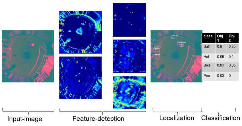
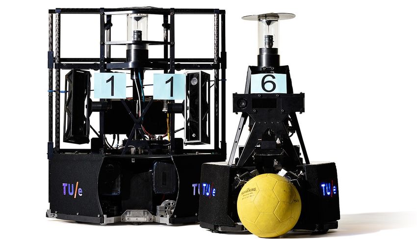
Fig. 1. Fifth generation TURTLE robots, with on the left-handside the goalkeeper
robot. (Photo: Bart van Overbeeke)

Through tournaments and numerous demonstrations, these platforms have evolved
into the fifth generation TURTLE, a very robust platform. For an outline of our
robot design the reader is referred to the schematic representation in [1]. A
detailed list of hardware specifications, along with CAD files of the base, upper-
body, ball handling and shooting mechanism, has been published on a ROP
wiki 1 . The software controlling the robots is divided into four main processes:
Vision, Worldmodel, Strategy and Motion. These processes communicate with
each other through a real-time database (RTDB) designed by the CAMBADA
team [2]. More detailed information on the software can be found in [3] or in the
flow charts as part of the qualification package.

3     Eight-Wheeled Platform

Last year, the mechanical design, presented in Figure 2(a), and the first version
of the low level control architecture of the eight-wheeled platform were pre-
sented [4]. The main advantages compared to the three-wheeled platform are
the possibility to apply the torque delivered by the motors in the desired move-
ment and the expectation to keep all wheels on the ground while accelerating. In
this section, first the improvements in the low-level control will be discussed. As
the eight-wheeled platform is non-holonomic while the current high-level soft-
ware assumes the platform to be holonomic, some adaptations have to be made
in order to be able to play soccer. The ideas on how to make this connection will
be elaborated in Section 3.2.

1
    http://www.roboticopenplatform.org/wiki/TURTLE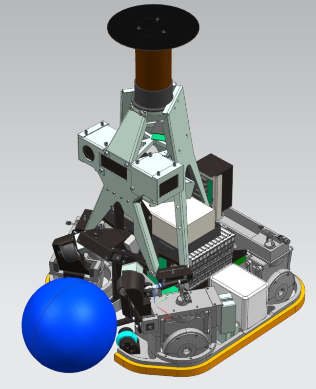
3.1   Improved Low-level Control Architecture

This platform consists of four sets each having two hub-drive wheels and thus five
times over-constrained. Each pair of wheels can rotate around its suspension by
actuating the corresponding wheels in opposite direction [4]. In order to actuate
the platform, last year a kinematic control scheme was presented. Here it was
observed that the performance was limited due to interaction between the wheels.
As a result, the control-architecture as shown in Figure 3 was designed.

                                                                    yw

                                                                             xw
                                                                               δ

                                                                y
                                                                     x
                                                                         φ
                                                               C

                                            Y

                                        O         X
       (a) Mechanical Design                    (b) Graphical Representation

Fig. 2. The eight-wheeled platform with four suspended wheel combinations which are
able to rotate around its center hinge.

For this controller, it is desired to manipulate the position x, y and orientation φ
of the center C of the platform. First is looked at the left lower part of this figure,
which is marked with ”Reference Generation of Pivots”. Here, the reference angle
δsp of each wheel-unit i = 1, 2, 3, 4 is based on the desired platform velocity
vsp = [ẋ ẏ φ̇]T using the inverse kinematics G of the platform. Here it is still
assumed that the platform is holonomic. As this is not the case and in order
to prevent step-responses, each pivot-setpoint is smoothed with a second order
setpoint generator. Next, in the right lower part of the same figure indicated
with ”Pivot Controllers”, each reference angle of the pivots is controlled using
a separate but identical position-to-force PD-controller Cδ . Here, the torque τw
has an opposite direction for each wheel in a wheel-unit. By designing a feed-
forward F Fδ for each pivot, the performance of these controllers is significantly
increased. Now, using an estimate of the wheel-velocities vw of each wheel and
the rotation δi of each wheel unit, the platform-velocity v is determined using
the forward kinematics J of the platform. This is required to control the motion
of the platform, shown at the left-upper part of the figure. As the platform is
non-holonomic, two velocity-to-torque PID-controllers are used to control three
degrees of freedom. The first controller Ct controls the translation by projecting
the velocity-errors ėx and ėy of both the x and y direction into the direction of
the setpoint. This is considered as the controllable direction, as the wheels are
kinematically oriented according to this reference. The orientation is controlled
using a separate controller Cr . Finally, the wrench wp is distributed among the
eight-wheels. It is still under investigation on how to improve this distribution.
Low-Level Motion Control
Platform Controllers
v
J (δ)
Velocity Controller
(Rotation) Forward Kinematics
Strategy ėθ
Cr (s)
Action Handler
Determine control ėx wp [2x1]
− v̂x ex
priorities
ėy ·
v̂y ey Ct (s) fτ (δ)
v̂x
s.t. = 1
v̂y 2
Control Velocity Controller Torque
Mode Project error in distribution
(Translation)
controllable space
Pivot Controllers
Determine Reduction F Fpl
Factor (x, y or φ) F Fδ
Reference Generation of Pivots
vw [8x1]
δ [4x1] Smooth δsp τw [8x1]
vsp [3x1] × G(δ) Cδ (s)
Pivots δ [4x1]
−
Inverse Kinematics 1D Trajectory Pivot angle
Generator (4x) controller (4x)
Fig. 3. Improved low-level control architecture of the eight-wheeled platform.
3.2 Integration into High-Level Software
The software used for the current three-wheeled platforms is designed assuming
the platform to be holonomic. As a result, the motion software will attempt to
control the position x, y, φ of the platform. For the eight-wheeled platform, this
is however not possible due to the non-holonomic constraints set by the pivots.
Therefore, in order to position at a specific location on the field, reducing small
positioning errors requires the pivots to change orientation continuously. As a
result, a large amount of energy is consumed in order to reduce these errors.
However, in order to play soccer, it is not always necessary to control all three
directions similarly. If, for example, the task of a robot is to intercept a pass, it
is important that it positions itself on the line of the movement of the ball. In
this situation, it is less important to position a bit more towards or a bit away
from the ball. Therefore, as shown in Figure 3, depending on the action set by
the high-level strategy, the relevant directions will be prioritized. This prioritymode is then communicated to the motion controller, where it is used to lower
the velocity references in the non-relevant directions.
4 Accurate Shooting
During matches it has been observed that the variation in the lob shots of the
robots is too large, causing a lot of shots at goal to miss [5]. This section elab-
orates on improvements of the shooting performance of the robots, to make lob
shots more reproducible. To this extent, two solutions are proposed. One so-
lution to gain improvements over short time, by adding a passive mechanism
to the shooting mechanism. In addition, one solution is to improve the shoot-
ing performance over longer time, uses the Kinect as a feedback mechanism to
calibrate the shooting mapping. This section is structured alike.
Thorough analysis of the cause of variation between the lob shots showed that
a significant amount of variation was caused by the shooting lever not returning
to its initial starting position before each shot. This results in the lever to have a
different velocity when it impacts the ball. To eliminate this cause of variation,
a passive mechanism was designed to retract the lever to its initial position, and
Fmag
to hold it at this position during driving.
Fmag
Fmag
Fmag
(a) end of stroke, after shot (b) rest position, before shot
Fig. 4. Schematical representation of how two sets of magnets ensure a consistent initial
position of the solenoid.
Figure 4(a) shows schematically how a set of repelling magnets push the lever
backwards when it has moved fully forward after a shot. A second set of magnets
at the front of the solenoid pulls the lever into the initial starting position,
and hold it there, Figure 4(b). Experiments and theoretical analysis showed no
observable decrease in shooting power using this mechanism. As a result, the
reproducability of the shot increased as the standard deviation decreased from
0.32 m/s to 0.08 m/s and from 1.06 degrees to 0.49 degrees for the ball’s starting
velocity and angle respectively.
Over longer periods of time (weeks, months), small changes in the shooting mech-
anism (lubrication, bearing performance) occur, which need to be compensated.
To shoot at a specifc target, the inverse dynamics of the shooting mechanism ismodelled in order to calculate the required robot inputs from a desired initial ball velocity v0 and angle α0 . For this mapping a second order polynomial de- scribing the robot shooting dynamics was chosen, since this was proven to be sufficient from previous research [6]. Using an extended Kalman Filter (EKF), the polynomial coefficients can be recursively updated after each shot while tak- ing the variation in the measured initial ball state into account. The state vector of the filter becomes x = [a0 a1 a2 a3 a4 a5 ]T , u = [K L]T . a0−5 are the polyno- mial coefficients, and K and L the shooting duty cycle and lever height settings respectively; the inputs of the shooting mechanism. Using the 3D Kinect camera mounted on the robot, the realised initial ball velocity v0 and angle α0 can be estimated in order to update the mapping. 5 Artificial Intelligence This section describes our efforts to arbitrary ball detection, subsection 5.1, and efforts towards learning opponent behavior, subsection 5.2. The latter is a con- tinuation of our work on recognizing robots in camera images [7] and predicting robot behavior [8] as described in [3,4]. 5.1 Arbitrary Ball Detection Ball detection is currently based on the upper and lower bounds of the YUV values of the ball its color. This detection method works fluently in most cases, however it comes with limitations. For example, changes in the brightness make the calibration of the upper- and lower bounds less accurate, the algorithm is more likely to make false predictions if the color of the ball is similar to its en- vironment, and the algorithm is only capable of detecting one-colored balls. To solve these inaccuracies and make the detection more humanlike, an ap- proach using a machine learning algorithm is proposed. The new ball detection algorithm uses multiple convolutional layers to create feature mappings of the camera frame. These feature maps are then used to localize potential ball loca- tions. Finally, the potential ball locations are classified through a neural network providing the probability-rate of the location actually holding a ball. Figure 5 visually represents the algorithm. A speed of 13 frames per second using only one CPU core with an accuracy of 80% on images with different balls with variable brightness and colors was achieved. In further research, the focus will be on implementation. The achievable speed on a Jetson board will be researched, if needed different ways of integration will be explored. 5.2 Analysis The arbitrary ball recognition may be combined with previous work on recogniz- ing robots [7] and forms the basis for a new method of building a shared world model. Currently the world model is based on conventional image processing
Fig. 5. Object detection algorithm

technology and kept as a logfile by all robots of the team. The aim is to use this
information to learn the behavior of competing teams and use this in our simula-
tor. The world model information from the TURTLEs during a game is obtained
with a frequency of about 10-30 Hz. In that data Game Turning Points (GTP)
are identified. GTP’s are points where a switch is made between attacking and
defending. Such situations occur typically when the ball is lost or regained, or
shot at the goal. Using these GTP’s all successful or failing episodes during a
game are found. Episodes describe a game moment as a series of successive steps.
The number of steps of an episode varies between just a few to sometimes several
hundreds of steps. Our analysis is limited to the last 100 steps of an episode.

5.3   Classification
Having collected these episodes, two functions are performed. First a Game Sit-
uation Image (GSI) is created for each step of an episode, analogous to the work
of van ‘t Klooster [8]. Then all episodes are classified according to its status as
being one of the following: Attack or Defend, Own Half or Opponent Half, Our
Ball or Opponent Ball and the starting situation, like Kickoff, ThrowIn etc. For
each step in an Episode, the movements of the four field players of a team are
calculated as single steps in the X and Y direction as Quantized Team Moves
(QTM). The GSI and its QTM steps are fed into a neural network and let the
network learn the relationships between the world model and moves. Because
each Episode leads to a desirable or undesirable situation, a reward or punish-
ment is assigned to the episode. This network then learns how a team responds
to the various game situations. Two different approaches will be tested: a Deep
Recurrent Q-Learning Network (DRQN) and a Deep Residual Network (DRN)
to find out which of these two approaches best captures the team behavior.
6    Conclusions
In this paper we have described the major scientific improvements of our soccer
robots over the past year. Our developments in the control of the eight-wheeled
platform expand to the platform and strategy level, bringing the introduction
of the eight-wheeled platform closer. By integrating magnets into the solenoid
assembly, we have reduced the standard deviation of our shots, increasing repro-
ducibility. For arbitrary ball detection we have verified the feasibility of a neural
network on the TURTLE’s computational units. The research to modelling op-
ponents continues, currently the classification process is revisited.
Altogether we hope our progress contributes to an even higher level of dynamic
and scientifically challenging robot soccer during RoboCup 2019 in Sydney, Aus-
tralia. The latter, of course, while maintaining the attractiveness of our competi-
tion for a general audience. In this way we hope to go with the top in Middle-size
league for some more years and contribute to our goal in 2050!

References
1. Lopez Martinez, C., Schoenmakers, F., Naus, G., Meessen, K., Douven, Y., Van De
   Loo, H., Bruijnen, D., Aangenent, W., Groenen, J., Van Ninhuijs, B., Briegel, M.,
   Hoogendijk, R., Van Brakel, P., Van Den Berg, R., Hendriks, O., Arts, R., Botden,
   F., Houtman, W., Van ’t Klooster, M., Van Der Velden, J., Beeren, C., De Koning,
   L., Klooster, O., Soetens, R., Van De Molengraft, R.: Tech United Eindhoven Team
   Description 2014. (2014)
2. Almeida Luis, , Santos, F., and Facchinetti Tullio, and Pedreiras Paulo, and Silva
   Valter, and Lopes L Seabra: Coordinating Distributed Autonomous Agents with
   a Real-Time Database: The CAMBADA Project. In Aykanat C., Dayar, T.,
   Körpeoğlu I., eds.: Computer and Information Sciences - ISCIS 2004, Berlin, Hei-
   delberg, Springer Berlin Heidelberg (2004) 876–886
3. Schoenmakers, F., Meessen, K., Douven, Y., Van De Loo, H., Bruijnen, D., Aan-
   genent, W., Van Ninhuijs, B., Briegel, M., Van Brakel, P., Senden, J., Soetens, R.,
   Kuijpers, W., Olthuis, J., Van Lith, P., Van ’t Klooster, M., De Koning, L., Van De
   Molengraft, R.: Tech United Eindhoven Team Description 2017. (2017)
4. Schoenmakers, F., Meessen, K., Douven, Y., Loo, H.V.D., Groot, C.D., Farahani,
   M.D., Lith, P.V., Scheers, P., Sommer, R., Ninhuijs, B.V., Brakel, P.V., Senden, J.:
   Tech United Eindhoven Team Description 2018. (2018)
5. Kengen, C.M., Douven, Y.G.M., Van De Molengraft, M.J.G.: Towards a More Re-
   producible Shot with the Tech United Soccer Robots. Technical report, Eindhoven
   University of Technology, Eindhoven (2018)
6. Senden, J., Douven, Y., van de Molengraft, R.: A Model-Based Approach to Reach
   a 3D Target with a Soccer Ball , Kicked by a Soccer Robot. PhD thesis, Eindhoven
   University of Technology (2016)
7. Van Lith, P., van de Molengraft, M., Dubbelman, G., Plantinga, M.: A Minimalistic
   Approach to Identify and Localize Robots in RoboCup MSL Soccer Competitions
   in Real-time. Technical report
8. van ’t Klooster, M., Nijmeijer, H., Dubbelman, G.: Deep Learning for Opponent
   Action Prediction in Robot Soccer Middle Size League. Technical report, Eindhoven
   University of Technology, Eindhoven (2018)
You can also read