FALCONS TEAM DESCRIPTION PAPER 2019 - ROBOCUP MIDDLE SIZE LEAGUE
←
→
Page content transcription
If your browser does not render page correctly, please read the page content below
Falcons Team Description Paper 2019

          Edwin Schreuder, Jan Feitsma, Erik Kouters, and Jaap Vos

                        Falcons, Veldhoven, The Netherlands
                         http://www.falcons-robocup.nl

      Abstract. The Falcons are a robotic soccer team participating in the
      RoboCup Middle Size League (MSL). Over the course of the last year,
      several significant improvements and investigations have been performed.
      This paper describes the most notable developments done in order to
      qualify for RoboCup 2019. These developments include the introduction
      of a novel mirrorless vision system, a redesign of the mechanical layout of
      the robot, the integration of new motor electronics allowing for improved
      motion control and the adaptation of the robot software to use Real-Time
      Database (RtDB).

1   Introduction
The Falcons are a robotic soccer team from Veldhoven, The Netherlands, who
participate in the RoboCup MSL. The team consists of around 30 ASML em-
ployees who share the same passion and vision: to work with robots as a hobby
and become champions in the RoboCup MSL league in the foreseeable future.
    The Falcons team was formed in November 2013 and forms a voluntary ac-
tivity outside working hours, actively encouraged and sponsored by ASML. We
share a passion for robotics, technical innovation and teamwork. Together we
try to maximize and expand the capabilities of our robots on software, hardware
and strategy. Key values for us are: sharing information, knowledge and having
fun. By sharing knowledge, we want to push forward the boundaries of the MSL
towards the main goal of robocup.
    An important aspect of the team is to teach and inspire children and stu-
dents for a technical career. To this end, the Falcons participate in several events
in the Eindhoven area for technical promotion, such as the Dutch Technology
Week, presentations and classroom training at secondary schools. Furthermore
we also provide opportunities for our members to improve their professional
skills. This can range from deepening the knowledge in their own field of ex-
pertise, to learning new technical or soft skills. In this way, team members can
prepare themselves for new challenges within ASML, and/or practice learnings
in their professional or day to day life.
    This paper gives a brief overview of the status of our soccer robots and de-
scribes the most significant investigations and improvements for 2019. In section
2, an introduction to the hardware and software of our current robot platform
is given. Section 3 presents the novel mirror-less vision system that was devel-
oped over the course of 2018. The ongoing effort to adapt the robot software
2      Falcons

to RtDB is described in section 4, while section 5 elaborates on the design of a
new electronics platform to improve the motion control of the robots. Finally,
the changes in mechanical layout of the robots are presented in section 6.

2   Robot Platform Overview
The Falcons MSL robots are based on the Turtle 5K design. Five years ago we
started working on improving the reliability and predictability of the robots.
This phase is successfully finished, playing most games with 5 robots in the field
and having a minimum of unexpected behavior/rogue robots.
    Since then, the focus shifted to optimizing the software and tactics of the
team; improving the control loops for faster moving and more accurate passing
next to better anticipation on the competitor. The team has defined a technical
roadmap which will constantly enrich the functionality of the existing robots and
improve parts which are fully utilized or end of life. The novelty for 2018/2019
was a mirror-less camera system, with the use of 4 cameras looking forward,
each covering 90 degrees. This concept was well received by our peers.
    Items on the roadmap are a lighter kicker design, new control electronics, and
improved ball handlers. At the 2017 world championship, the robots were at the
maximum weight limit of 40Kg. A weight reduction is needed to enable hardware
additions in the future. A weight plan of all components was created and the
base plate is changed from steel into aluminum. First steps are taken to redesign
the internal structure of the robot and change the shooting height mechanism.
Together those groups contribute for half the robots weight. The battery packs
are now of the NiMh type, and the idea was to go to a LiPo system, but this
was abandoned because of Air Traffic regulations and technical complexity.

3   Mirror-less MSL Vision System
The multiCam is a novel, multi-camera setup to achieve robot omni-vision, with-
out the use of a parabolic mirror as was present in the original Turtle 5K design.
The system consists of an assembly of four Raspberry Pi v2.1 cameras (Sony
IMX 219) each connected to their own Raspberry Pi model 3 B+, a network
switch (Netgear GS108) and several power supplies, and is connected to the
main Central Processing Unit (CPU) (Intel i7-6700) in the robot. A mechanical
overview of the multiCam setup is depicted in Figure 1.
    The multiCam system was introduced on the robots mainly because the
range of the previous vision system proved too limited. The decision was made
to choose for multiple cameras instead of a single camera, mirror-based setup,
for various reasons.
    For instance, when using front-facing cameras, the mounting can be adjusted
such that the main part of the camera image is used to register details that
are relatively far away from the robot. In contrast, when using a parabolic mir-
ror, one has to use the image reflected towards the edges of the mirror where
distortion is most prominent. Also the number of available pixels is increased.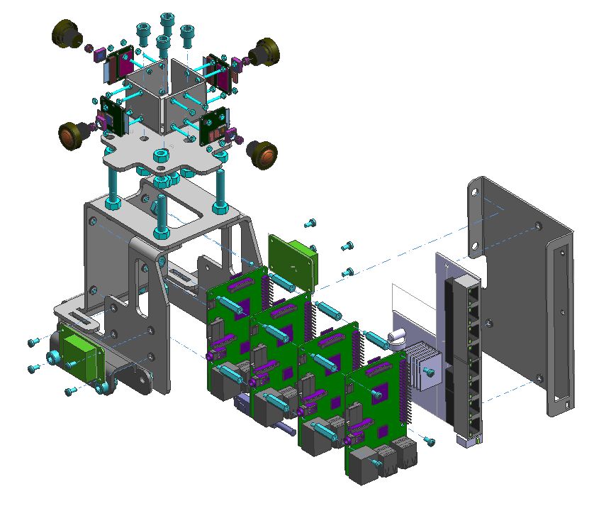
Falcons Team Description Paper 2019         3

                    Fig. 1: Multi-camera setup for omnivision

    Another advantage of the multiCam setup is that the cameras are positioned
radially on the robot. This not only allows for registering objects on the ground,
but also those flying in the air. For this reason, airborne balls can be almost
continuously detected, leading to strategic advantages and more accurate ball
tracking.
    Finally the potential for applying parallelism in the detection algorithms is in-
creased when using multiple cameras, as processing of the image feeds can easily
be distributed over multiple processors or even different computation platforms.
This also implies that the concept is inherently scalable.
    The images that are captured by each camera are first acquired and filtered
by the Raspberry Pi. At this stage the camera hardware control, color conversion
(RGB to HSV) and detection, and detection of objects with similar colors (e.g.
lines) takes place. Vector data of these objects is then forwarded to the main
CPU. The multiCam software on the CPU then tries to determine the position
of the robot on the field and to identify balls and obstacles.
    In order to improve the portion of the field that can be seen by the cameras,
the viewing angle of the cameras has been increased by replacing the default
lenses that are supplied with the Raspberry Pi cameras with fisheye lenses.
Furthermore, the cameras are rotated by 90 degrees such that the wide angle is
in the vertical plane.
    The lenses themselves have been adjusted such that the camera maintains
infinity focus, where the center of the camera is directed at the horizon. The
selection of the lenses has been such that the robot is able to see the ball near
its base and cover a full 360 degrees of vision, with each camera overlapping for
about 5 degrees. An example of an image captured by one of the cameras of a
18 by 12 meter field is displayed in Figure 2.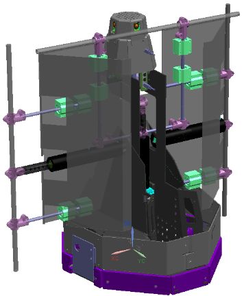
4       Falcons

                  Fig. 2: Raw vision image from a single camera

4     RtDB Transition in Robot Software

Up to this year, the Inter-Process Communication (IPC) on the robots was gov-
erned by the Robot Operating System (ROS) and the inter-robot communication
was supported by a self-built UDP messaging protocol. Although functional, this
setup had several disadvantages. For instance the messaging framework, as well
as the facilities provided by ROS have high resource usage, adding latency to
the robot performance and development cycle. Furthermore, our WiFi band-
width usage during RoboCup 2018 was very high.
    In order to simplify and speedup both the IPC and inter-robot communi-
cation, while leveraging the work that has been done by CAMBADA [1], we
are adopting the RtDB2 library. This has the added benefit that it can replace
custom-made software facilities (such as data logging, sync protocols), and en-
able new improvements (such as (wifi) data compression, simulation). This has
turned out to be a major software redesign activity, yet the investment is still
found to be worth the effort.

4.1   Changes in Execution Architecture

The software architecture in the robot consists of a number of software com-
ponents that each take input data and convert it into output data. For exam-
ple, the Teamplay component takes the world state as input data and makes
a decision on which action the robot should take, which is Teamplay’s output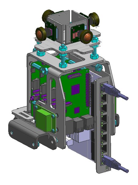
Falcons Team Description Paper 2019        5

data. Subsequently, MotionPlanning takes the output data of Teamplay and uses
it to define setpoints for PathPlanning, ShootPlanning and BallHandling. Our
complete software architecture is designed in such a cascading flow of software
components that convert specific input data into output data.

                   Fig. 3: Software Control Flow using RtDB

    ROS offers a facility to put a software component to sleep, and wake up as
soon as new data is available. This design introduces less latency compared to a
design where every software component sleeps and wakes up after a fixed time
interval.
    With the transition from ROS to RtDB, the facility to wake up a software
component when new data is available was no longer available. For this reason,
RtDB was extended with an interface named wait for put during the 2018 MSL
Workshop in Aveiro, Portugal. Figure 3 shows the different RtDB data elements
which trigger the software component to wake up using wait for put.

4.2   Logging
A facility was written to write RTDB frames as binary into a file. Here, a frame is
a sequence of key/value pairs specific to one robot, as used by the comm process.
The visualizer can read data from such files and browse through it. This logging
functionality will be proposed as extension to the Cambada RtDB2 package.
    Additionally, this logging facility allows us to apply a new kind of component
testing. Each software components typically takes an input data stream and
produces an output stream. Given a log file, any component under test can be
6 Falcons
put under test and will create a new output log file. This proves to be very
valuable for regression and progression testing.
4.3 Comm2
The comm utility is in need of improvement. For instance, it turns out the
data sub-sampling option is not yet implemented. Furthermore its code quality
could be improved as well. We are considering to use comm2 to sync timestamps
between robots, taking over the responsibility of ntp. At the time of writing, we
are still working on defining and implementing comm2. Once finished, it will be
proposed as improvement to the Cambada RtDB2 package.
5 Motion Control Electronics Platform
The electronic controller boards present in the robots over the last years were
part of the original Turtle 5K design. Unfortunately, these existing controller
boards are not good in terms of reliability. After repeated improvement effort in
hardware and software, the serial and USB communication between the CPU and
the controller boards still suffers from sudden resets, hickups and connectivity
issues.
Furthermore, the control system is limited in functionality. The motor con-
trollers are for instance not able to actively monitor or limit the current, which
has resulted in several burned motors. The lack of torque feedback and the low
sampling rate (100Hz) limits the controllability of the system and the type of
control algorithms that can be applied. Finally the controllers do not allow for
brushless motors and software upgrades can only be applied manually.
In order to attain faster and more precise controlled motion and improved
ball handling and shooting accuracy, it is key that these problems are resolved.
For that reason effort has been put in the design of a new motion electronics
platform, which is depicted in figure 4.
The platform is centered around a so-called Motion Control Board (MCB),
which will govern the active motion feedback control of the robot. In practice this
MCB is implemented as BeagleBone Black (BBB) to which all the peripheral
hardware on the robot is connected. The three driving motors and encoders,
as well as the ballhandler motors, tachos and angular sensors, are connected
via Maxon EPOS4 (Compact 50/15) positioning controllers over EtherCAT to
the MCB. All devices previously connected to the Input-Output board, i.e. the
kicker height adjustment, capacitor charging, kicker solenoid and switches on
the robot, are rerouted to the MCB as well. In addition a Inertial Measurement
Unit (IMU) is connected directly to the board. As such, the board serves as
general hardware interface module towards the CPU.
The MCB will mainly be used to orchestrate the motion control of the robots
and the ball handling. By using communication over EtherCAT a sample rate
towards the motor controllers of 1000 Hz can easily be achieved. The control
loop and logging can therefore also be applied at 1kHz, which will add to theFalcons Team Description Paper 2019 7
diagnosability and controllability of the robot. By deploying this part of the
robot control on a dedicated board, the CPU can run on the frequency dictated
by the acquisition of vision, while the MCB can run on the higher frequency
necessary for motion control.
Additionally, by introducing the IMU to the system, the motion control need
not only rely on the odometry data that is sourced from the motor. Instead,
sensor data from the motor encoders and IMU can be fused, allowing for more
accurate position or velocity control at a low level.
Fig. 4: Motor Control Platform using EtherCAT
6 Mechanical Robot Layout Redesign
The mechanical layout of both the keeper and the field players has been re-
designed, and are shown in Figures 5a and 5b. This was primarily done to incor-
porate the new motion control electronics and attain weight reduction. Next to
that the frame bottom plate has been upgraded, as an earlier attempt to reduce
its weight of left the structure prone to unwanted deformation during games
and transport. In the Team Description Paper of 2018 [2] the development of
the moving keeper frame was discussed, yet it proved difficult to integrate the
hardware for the moving keeper frame in the existing Turtle 5K hardware. In
this year’s updated keeper design, the integration of the moving keeper frame
and its actuators has been explicitly taken into consideration.
References
1. Almeida, L., Santos, F., Facchinetti, T., Pedreiras, P., Silva, V., Seabra Lopes,
L.: Coordinating Distributed Autonomous Agents with a Real-Time Database: The
CAMBADA Project. In: Computer and Information Sciences - ISCIS 2004, Aykanat,8 Falcons
(a) Field player design (b) Keeper design
Fig. 5: Mechanical robot architecture
C., Dayar, T., Körpeoğlu, İ., (Eds.), Lecture Notes in Computer Science, LNCS, Vol.
3280, pp. 876–886. Springer, Heidelberg (2004). https://doi.org/10.1007/978-3-540-
30182-0 88
2. Vos, J.: Team Description Paper, Qualification for World Championship Montreal,
Canada 2018, http://www.falcons-robocup.nl/images/Qualification-2018/
falcons_team_description_2018.pdfYou can also read