GLORUNNER MICROPLATE LUMINOMETER OPERATING MANUAL
←
→
Page content transcription
If your browser does not render page correctly, please read the page content below
GloRunner™ Microplate Luminometer
              Operating Manual

                        Dated: 09/18/2006
                           Version: 1.2
                      Part Number: 998-9005

               645 N. Mary Avenue Ÿ Sunnyvale CA 94085
               Phone: 408.636.2400 Ÿ Toll Free: 888.636.2401
               Fax: 408.737.7919 Ÿ www.turnerbiosystems.com

www.turnerbiosystems.com                                       1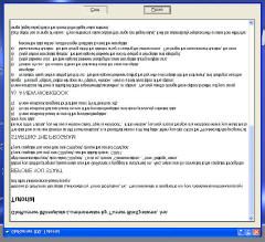
Table of Contents
I. Introduction 4
Description 4
Inspection 4
General Precautions 4
II. Hardware Overview 5
Functions and Features 5
III. Setting up the GloRunner™ Microplate Luminometer 7
Procedure 7
IV. GloRunner™ Microplate Luminometer DXL Software 7
Overview 7
Software Operation 9
Communications Settings Procedure 11
GloRunner™ User Interface Features 13
Setting the Options 14
V. Reading Samples 16
Starting a Run 16
VI. Calibration of the GloRunner 17
Procedure 17
VII. Relative Light Units and Common Questions 19
Overview 19
FAQs: 19
APPENDIX A - Installing the Software 21
Overview 21
Procedure 21
APPENDIX B - LED Messages and Firmware Upgrades 23
LED Lights 23
Firmware Upgrades 23
www.turnerbiosystems.com 2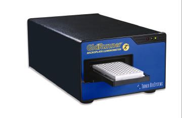
APPENDIX C - Maintenance, Warranty, & Service 24
Maintenance 24
Warranty 24
Obtaining Service 25
Warranty Service 25
Out-of-Warranty Service 26
Address for Shipment: Error! Bookmark not defined.
APPENDIX D – Specifications 27
Specifications for the GloRunner Microplate Luminometer 27
www.turnerbiosystems.com 3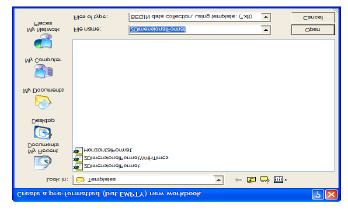
I. Introduction
Description
The GloRunner is an easy-to-use, sensitive luminometer with a broad
dynamic range designed to read glow luminescent reactions in 96-well
plates. The instrument’s small size and affordable price make it an
ideal laboratory instrument. This manual is designed to guide you
through the installation, setup, calibration, and operation of your
instrument.
Inspection
Upon receiving your luminometer, please inspect it carefully and make
sure all accessories are present (refer to the packing list shipped with
the instrument).
Standard accessories:
v Power Cord
v 9-pin Serial Cable
v Operating Manual
v Quick Start Guide
v Software
General Precautions
v This instrument is intended for indoor use only.
v A clear, transparent adhesive film should be placed over the 96-
well microplate to prevent spills or cross-contamination between
wells.1
v Wipe up spills immediately. See Appendix C for cleaning
instructions.
v The luminometer contains sensitive optical components and
precision-aligned mechanical assemblies. Avoid rough handling.
1
This adhesive film may be purchased at Rainin, catalog no. 96-SP-100
or any similar manufacturer.
www.turnerbiosystems.com 4II. Hardware Overview
Functions and Features
This section describes the various hardware features of the GloRunner, with
Figures 1-3 as references.
v LED Status Lights: These lights report the status of the
instrument. The green LED indicates the unit is on and ready. A
solid yellow LED indicates the instrument is not communicating
with the host computer. The red LED indicates a potential
component failure within the instrument. See Appendix B for a
detailed description of what the lights represent.
v Sample Tray: Sample plates are placed on the tray for reading.
The plate format for this version is 96-well. No other well format
can be read.
v Drawer: The drawer opens to receive sample plate.
v Power Switch: The ON/OFF switch is located on the back panel
of the instrument.
v Power Cord Connection: The power cord connects into the rear
panel of the instrument.
v RS-232 Serial Port Connection: The 9-pin serial port is used to
connect the GloRunner to a computer via the RS-232 cable.
v RS-232 Cable
www.turnerbiosystems.com 5Figure 1
LED Status
Lights
Drawer
Sample Tray
Figure 2
9-pin Male Connector
9-pin Female Connector
(To GloRunner)
(To Computer)
RS-232 Serial
Port
Connection Power Power Cord
Switch Connection
Figure 3
www.turnerbiosystems.com 6III. Setting up the GloRunner™ Microplate Luminometer
Procedure
1. Position the instrument on a flat surface. Leave enough room for the sample
tray to extend in front of the unit (approximately 7 inches).
2. Plug in the unit. In some countries, the power plug provided may not match
the wall connection. If this is the case, you can use the appropriate power
cord if the input power is between 100 and 240 volts AC, and the nominal
frequency is between 50 and 60 Hz.
3. From your own computer, install the software according to the instructions
in Appendix A.
4. Connect the 9-pin serial cable between the luminometer and the computer.
The male 9-pin connector attaches to the GloRunner and the female 9-pin
connector attaches to your computer (See Figure 2).
5. Turn on the power switch (rear of unit).
Note: The sample tray opens and closes via the software user interface. To
open the sample tray, please proceed to the next section for further
instructions.
IV. GloRunner™ Microplate Luminometer DXL Software
Overview
The GloRunner Microplate Luminometer DXL software is very easy to use.
This direct-to-Excel based software is designed to give the user flexibility in
data retrieval, storage, and manipulation while using the GloRunner
Microplate Luminometer. User-defined protocols can be stored as templates for
easy retrieval of stored settings. For added help while using the GloRunner
DXL software, a tutorial is available. You will see the following dialog box
after clicking on the GloRunner icon from your desktop (an alternate way of
accessing the GloRunner DXL software is through the program manager):
Figure 4
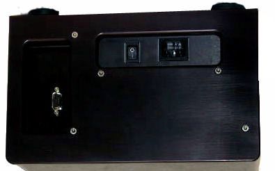
www.turnerbiosystems.com 7If you elect to review the tutorial, you will see the following tutorial window. The tutorial can be printed by clicking the “Print” button. Figure 5 When you are done reviewing the tutorial, click the “Close” button to close the window. www.turnerbiosystems.com 8
The following dialog box will appear after closing the tutorial, or if you elect not to review the tutorial: Figure 6 Software Operation The GloRunner DXL software is designed to run in conjunction with Excel. When using the GloRunner Microplate Luminometer, you have two workbook options. The first option is to create a new workbook for data collection. This option should be selected when first using the GloRunner. The second option is to use an existing workbook. This feature allows you to add data to an existing workbook. This should be selected if you would like to keep a running log of data from multiple assays. If you are using the luminometer for the first time, select the “Create a new workbook” option. Once this is selected you will be prompted to select a data storage template format. We suggest using the “2DimensionalFormat” template. The “2DimensionalFormatWithTimes” template can also be used if you are interested in knowing well read times. Figure 7 shows the workbook selection screen. Figure 7 www.turnerbiosystems.com 9
After selecting the data storage format, the GloRunner dialog box will open along with the active Excel spreadsheet. You should see the following on your screen. Note: These are two separate windows. Figure 8 The top window is the GloRunner dialog box. The bottom window is the active Excel spreadsheet in which data from the run will appear. The dialog box is used for starting runs, changing or selecting options, toggling the tray position, and establishing communication between the GloRunner and the computer. If communication has not already been established between the GloRunner and the computer, this should be done now. www.turnerbiosystems.com 10
Communications Settings Procedure
1. Select Communications from “Settings” on the GloRunner dialog box
pull-down menu, and the screen in Figure 9 will be displayed.
Figure 9
2. Select the proper COM port and click on “OK”. The COM port selection
depends upon the computer that is connected to the instrument. If you are
unsure of which COM port to select, select COM 1 and proceed to the next
step.
Figure 10
www.turnerbiosystems.com 113. Click on the “Tray In/Out” option, see Figure 11. If an error message
appears, such as the one displayed in Figure 12, go back to step 2, and
select the next COM port. For most computers, the COM port selection will
need to be either COM 1 or COM 2. If no error message appears, and the
tray door opens this is the correct COM port. Please note the COM port
selection for future reference.
Figure 11
Figure 12
www.turnerbiosystems.com 12GloRunner™ User Interface Features
The GloRunner user interface has some built-in features to assist you while
using the GloRunner. The first feature is mouseover messages. These
messages appear when the mouse pointer is stationary over a button for longer
than 1 second. An example can be seen in Figure 13.
Figure 13
The status bar is another useful GloRunner feature. It indicates the status of
the GloRunner during operation. For example, the following message is used
to indicate that the GloRunner is getting ready to take readings:
Figure 14
The GloRunner tray detection mechanism is helpful in two ways:
v This mechanism prevents plates being unintentionally left in the
GloRunner. If you have not selected the option to have your
plate stored inside the instrument after the run, the plate will be
automatically ejected. This will help prevent the evaporation of
fluid from the plate into the internal parts of the instrument.
v The tray detection mechanism will also detect the absence of a
plate if you initiate a run without a plate in the sample tray. You
will be prompted with the following message:
Figure 15
www.turnerbiosystems.com 13Setting the Options
Once the communications settings are properly set up, click on the "Tray In/
Out" button. If the tray door opens and closes, the proper communication has
been established.
1. Click on “Options” to access the options screen as shown in Figure 17.
Figure 17
2. There is an option to set a delay time before the first measurement is made.
The delay time can be set between 0-150 minutes.
3. The instrument can be set up for a single run of multiple runs. To read the
plate once, select “1” in number of runs. To run the same plate multiple
times, select a number for multiple runs. You can select up to 999 runs of
the same plate with up to a 999-second delay between the end of one run
and the start of the next run.
4. The GloRunner™ will automatically eject the microwell plate at the end of
the run. If you prefer to temporarily store the plate within the instrument
after the run, select the “Delay, before microplate ejection” option. The
plate can be stored inside the instrument for up to 150 minutes after the run
has been completed. Once the delay time has expired, the plate will be
ejected.
5. The measurement duration may also be selected. The measurement
duration is the time in which the detectors sit over the well. During this
time the measurements are averaged for more accurate measurements.
Note: A longer measurement time does not mean larger RLU values.
www.turnerbiosystems.com 146. Select the wells you want to read. If the well is highlighted in blue, the well
will be measured. Select or de-select all the wells by clicking the “All”
button in the top left corner of the grid. Alternatively, individual rows and
columns can be selected or de-selected by pressing the letter or number at
the head of the row or column. Select or de-select individual wells by
clicking on that well.
7. Once you have made your selections, click the “OK” button.
8. The Excel Spreadsheet also contains the reading parameters as seen in
Figure 18.
Figure 18
www.turnerbiosystems.com 15V. Reading Samples
Starting a Run
The process of reading samples with the GloRunner is simple. The instrument
will read only the wells that are selected in the Options menu. Any skipped
wells are denoted with an “X” in the data. To read samples:
1. Fill in any information you would like in the Operator, Test, and Notes
section.
2. Verify that the Options menu has the correct wells selected and the correct
number of runs selected.
3. Open the sample tray door if it is not already open. If the tray door is
closed, click the “Tray In/Out” button on the GloRunner Dialog Box.
4. Insert the plate in the sample tray so that well A1 is positioned to the right
rear of the sample tray.
5. Click on the “Start” button in the software to close the sample tray and start
the instrument.
6. The GloRunner will read the whole plate in approximately 30 seconds if
the measurement duration is set at 1 second. Once the run is complete,
results will appear in the Excel spreadsheet.
Note: It is highly recommended that you elect to save your data at this
time. Your data may be lost if you choose not to save at this time.
7. If multiple runs were selected, subsequent runs will appear on the Excel
Spreadsheet in the respective run order (See Figure 19).
Figure 19
www.turnerbiosystems.com 16VI. Calibration of the GloRunner
Overview
Calibration of the GloRunner is possible if you purchased the GloRunner
Standardization Light Plate. The calibration procedure is password protected and
should only be done after contacting Turner BioSystems for the password. This
calibration is a process that normalizes the detectors and is not usually required.
If it is determined that detector normalization is required, choose “Utilities” on
the pull down menu. Next select “Calibrate Using Light Plate”. You will see the
following pop-up menu:
Figure 20
Procedure
1. Type in the password and click on the “Enter New Password” button. You
will be prompted with the following pop-up button.
Figure 21
2. Turn on the light plate by briefly pressing on the “Start” button. Insert it
into the sample tray with the proper plate placement. (Proper plate
placement is the alignment notch corner of the light plate to the right rear
of the sample tray. See Figure 22). Click “OK”.
Figure 22
www.turnerbiosystems.com 173. Once “OK” is clicked the plate will be drawn into the GloRunner and the
detectors will be standardized.
4. If you see a message similar to Figure 23, and your light plate is powered
on, please contact Turner BioSystems for support:
Figure 23
www.turnerbiosystems.com 18VII. Relative Light Units and Common Questions
Overview
The GloRunner Microplate Luminometer’s output is in relative light units.
This means that there is no absolute way to quantitate the number of photons
emitted from the sample. This is true for all luminometers. All luminometers
are “photon counters”, but no luminometer manufacturer can claim that the unit
output of the instrument is in photons. This poses a dilemma for many
researchers. The next section contains some common questions and answers.
FAQs:
Q: How do I determine which luminometer is more sensitive?
A: The best way to do this is to run a side-by-side comparison between
instruments with samples that are representative of your experiment.
Compare the statistics of a group of replicate samples and blanks for
both instruments. It is not sufficient to compare the statistics on the
blanks alone because the samples give a relative scale of the light units
between different instruments. If a detailed sensitivity study with
multiple serial dilutions of the sample is not possible, a common tool
for determining rough sensitivity is %CV. %CV is defined as the
standard deviation of a group of samples divided by the average of the
samples. If the blank is non-zero, the %CV should be blank-corrected.
The blank-corrected version of the %CV is shown below:
STD DEV (samples – average blank)
Average(samples) – Average(blank)
Q: Which plates should I use with my luminometer?
A: For weakly luminescent samples, white plates give better results
because they reflect more light to the instrument’s detector.
Q: What luminescent assays can I run on the GloRunner Microplate
Luminometer?
A: The instrument is designed for glow luminescent reactions, so any
chemistry that has a half-life of 3 minutes or greater is appropriate.
www.turnerbiosystems.com 19Q: What is the purpose of the Dark Current Log? A: The Dark Current is a measurement the detectors make in a position on the instrument that represents total darkness. These measurements are logged for technical support purposes. Logging these values can be valuable in diagnosing instrument related performance issues. Q: Why is the calibration procedure password protected? A: Calibration of the detectors is only needed under rare circumstances. We would like to be certain that you have spoken to a technical support person before you calibrate the detectors to be sure this will solve the problem. www.turnerbiosystems.com 20
APPENDIX A - Installing the Software
Overview
Installing the software on your computer is the next step once you have
verified that all the components of your instrument are present. This
software requires Windows® 95 or later. To install the software, follow
the instructions below:
Procedure
1. Place the CD disk of the Turner BioSystems GloRunner Microplate
Luminometer software in the D: drive of your computer. Most computers
will automatically start the installation process once the disk is placed in the
CD-ROM. If your computer automatically installs, you will see the
InstallShield Wizard screen show in Figure 24.
Figure 24
2. If your computer does not automatically start the installation process, click
the “Windows Start” button, and select “Run”. Type in D:\setup.exe if your
disk drive is drive D, or substitute D with the letter that represents your
CD-ROM drive.
www.turnerbiosystems.com 213. Follow the instructions given during the installation process. The default
directory for installation is C:\Program Files\Turner
BioSystems\GloRunner. To select an alternative directory, click on the
“Change” button shown in Figure 25 and choose your directory option as
seen in Figure 26. Click the “OK” button when you are ready to continue
with the software installation.
Figure 25
Figure 26
www.turnerbiosystems.com 22APPENDIX B - LED Messages and Firmware Upgrades
LED Lights
There are 3 LED status lights on the front panel of the GloRunner.
v The green LED is the power indicator. When it is illuminated the
instrument is powered and ready.
v The yellow LED indicates communication errors between the
GloRunner and the computer. An illuminated yellow LED indicates
no communication between the computer and instrument is being
made. This can occur under the following circumstances:
§ The GloRunner is powered on and the User Interface is not
open on the computer.
§ The GloRunner is powered on and the RS-232 is not
connected to the computer.
v The red LED indicates other types of errors. When the red LED is
illuminated a potentially serious error has occurred. At this point you
should contact Turner BioSystems technical support for further
instructions.
Firmware Upgrades
The GloRunner Microplate Luminometer has the capability to download new
firmware to the instrument from the PC. This capability is reached through the
Utilities Menu (Figure 27). This is a password protected function to prevent
accidental use. The main purpose of firmware upgrades is to add new
capabilities to the system. When a new version firmware is needed in the future,
you will receive specific instructions on how to perform the upgrade.
Figure 27
www.turnerbiosystems.com 23APPENDIX C - Maintenance, Warranty, & Service
Maintenance
v If you suspect fluids may have been spilled onto the detectors,
please contact Turner BioSystems for cleaning instructions.
v Periodically wipe off the outside of the instrument with a damp
cloth. Do not use solvents or abrasive cleaners to clean the
instrument.
v Avoid spilling liquids into the sample tray. If there is a spill:
1. Unplug the instrument.
2. Wipe up any moisture inside the sample chamber.
3. Use a damp ChemWipe wetted with a 70% ethanol, 30%
water solution to clean the tray.
4. Plug in the unit and turn on the power. Allow it to stay on for
a few minutes or until completely dry inside.
Warranty
Turner BioSystems warrants the GloRunner Microplate Luminometer and
accessories to be free from defects in materials and workmanship under normal
use and service for a period of one year from the time of initial purchase, with
the following restrictions:
v The instrument and accessories must be installed, powered, and
operated in compliance with the directions in this Manual and the
directions accompanying the accessories.
v Damage incurred during shipping is not covered by warranty.
v Damage resulting from measurement of samples found to be
incompatible with the materials used in the sample system is not
covered.
v Damage resulting from reagent spills is not covered.
v Damage resulting from contact with corrosive materials or
atmosphere is not covered.
v Damage caused by modification of the instrument by the customer
is not covered.
www.turnerbiosystems.com 24Obtaining Service
Warranty Service
1. To obtain service during the warranty period, please take the following
steps:
Write or call the Turner BioSystems Service Department and describe as
precisely as possible the nature of the problem.
2. Carry out minor adjustments or tests as suggested by the Service
Department.
3. If proper performance is not obtained, YOU MUST OBTAIN AN RMA
number BEFORE shipping the instrument to Turner BioSystems.
4. After obtaining an RMA number, pack the instrument well (damage
incurred in shipping due to improper packing is not covered); insure it;
write the RMA number on the outside of the carton and ship it to Turner
BioSystems prepaid.
v The instrument will be repaired and returned free of charge for all
customers in the United States. Turner BioSystems will pay for
return shipment and include a check to reimburse you for the cost
of surface shipment to us.
v If you are an international customer who purchased directly from
Turner BioSystems (not from a third party distributor), contact
Turner BioSystems for instructions. The instrument will be
repaired at no charge if it is under warranty. Turner BioSystems
cannot, however, pay shipping, duties, or documentation costs
outside the continental United States.
v For customers outside of the United States, who have purchased
our equipment from an authorized distributor, contact the
distributor for further instructions.
Note: Under no circumstances should the instrument or accessories
be returned without prior authorization from Turner BioSystems or
our authorized distributor. Prior correspondence is needed:
§ To ensure that the problem is not a minor one, easily
handled in your laboratory, with consequent savings
to everyone.
YOU MUST § To specifically determine the nature of the problem,
INCLUDE AN so that repair can be done with particular attention
RMA NUMBER paid to the defect you have noted.
ON ALL
EQUIPMENT
RETURNS.
www.turnerbiosystems.com 25Out-of-Warranty Service
v Proceed exactly as for Warranty Service above. Our service
department is happy to assist you by phone or correspondence at
no charge.
v Repair service will be billed on a flat rate basis. Your invoice will
include freight charges.
Address for Shipment:
Turner BioSystems
645 N. Mary Ave.
Sunnyvale, CA 94085
USA
Telephone: 408-636-2400
Toll-Free: 888-636-2401 (US & Canada)
Fax: 408-737-7919
Email: techsupport@turnerbiosystems.com
www.turnerbiosystems.com 26APPENDIX D – Specifications
Specifications for the GloRunner Microplate Luminometer
Sensitivity 2x10-20 moles horseradish peroxidase
2x10-20 moles alkaline phosphatase
5x10-18 moles luciferase
Linear Dynamic Instrument dynamic range 108
Range
Cross-talk Better than 5x10⁻⁴ at 1.5x10⁶ Relative Light Units using
a white Costar plate
Detector Proprietary eight-channel solid state array
(patent pending)
Spectral Response 300—610 nm
Range
Peak Wavelength 550 nm
Detection Mode Glow luminescence
Plate Format 96-well
Reading Speed 1 second per well, less than 30 seconds per plate
Computer RS-232
Interface
User Interface User-friendly Windows® software controls machine
functions. Requires Windows® 95 or later
Power 0.5A @ 100—240V, 50—60Hz (universal)
Dimensions 16.75” D x 10.25” W x 6.75” H
(42.6 cm D x26.0 cm W x 17.2 cm H) (tray closed)
Weight 20 lbs (9.1kg)
Operating 60—105°F (15—40°C)
Temperature
Warranty One-year warranty
Approvals CE, UL, CUL (pending)
www.turnerbiosystems.com 27You can also read