Technical Committee on Resistance and Propulsion 2017-2021
←
→
Page content transcription
If your browser does not render page correctly, please read the page content below
Technical Committee on Resistance and Propulsion

 2017-2021

Chairman : Richard Pattenden
Members : Nikolaj Lemb Larsen, João L. D. Dantas, Bryson Metcalf, Wentao Wang, Yasuhiko
Inukai, Tokihiro Katsui, Seok Cheon Go, Haeseong Ahn, Patrick Queutey, Devrim Bulent
Danisman, Yigit Kemal Demirel, Aleksey Yakovlev
Members
Member Affiliation
Richard Pattenden QinetiQ, UK
Nikolaj Lemb Larsen FORCE, Denmark
João L. D. Dantas IPT, Brazil
Bryson Metcalf Naval Surface Warfare Center, Carderock Division, USA
Wentao Wang China Ship Scientific Research Centre, China
Yasuhiko Inukai Japan Marine United Corporation, Japan
Tokihiro Katsui Kobe University, Japan
Seok Cheon Go HHI, South Korea
Haeseong Ahn KRISO, South Korea
Patrick Queutey ECN, France
Devrim Bulent Danisman Istanbul Technical University, Turkey
Yigit Kemal Demirel University of Strathclyde, UK
Aleksey Yakovlev Krylov State Research Centre, Russia

 2 13/05/2021

Meetings
 FORCE, Copenhagen,
 Denmark
 May 2019
 QinetiQ, Gosport, UK
 January 2018

 KRISO, Daejeon, Korea JMUC, Yokohama,
 January 2020 Japan
 October 2018

 3 13/05/2021
Tasks
• Development of a procedure for wave profile measurement • Monitor the use of and, if possible, develop guidelines for
 and wave resistance analysis. quasi-steady open water propeller and propulsion model
 tests.
• Investigate feasibility of a procedure for verification and
 validation of the detailed flow field data. • Conduct a survey of cavitation erosion modeling and
 prediction methods.
• Cooperation with other committees:
 • Specialist Committee on Energy Saving Methods on subjects of • Identify the need for a procedure concerning rim drive
 common interest. model testing and performance prediction.
 • Specialist Committee on Ships in Operation at Sea
 • Specialist Committee on Combined CFD/EFD Methods
 • Identify the influence of the new FD definition on power
 prediction.
• Investigate and propose new roughness correction
 methods for both hull and propeller. • Investigate the need to change the standard criterion for
 Re in model tests of propulsors as well as in the aspect of
• Validate procedure 7.5-02-03-01.7, 1978 ITTC CFD validation.
 Performance Prediction Method for Unequally Loaded,
 Multiple Propeller Vessels. • Investigate the need of change of scaling methods with
 regard to propulsors (including pods).
• Continue with the monitoring of existing full scale data for
 podded propulsion. • Investigate and describe a propulsor performance in
 waves, and discuss the scale effects on its modelling.

 4 13/05/2021
Review of state of the art

Update the state-of-the-art for predicting the performance of different ship concepts
emphasizing developments since the 2017 ITTC Full Conference.

 13/05/2021
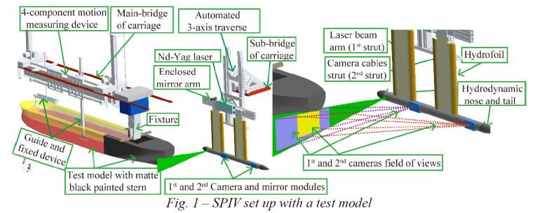
New experimental techniques and extrapolation methods

• Resistance
 • Ship model tests
 • Air-bubbling technique
 • Ship-wave-ice interaction
 • Measurement technologies (*PIV, LDV, OCT)
 • Flow over rough surface, compliant coating, etc.
 • Stern-wake measurement Luo et al. (2018)’s experimental setup with paraffin model ices to
 investigate ship-wave-ice interaction
 • Extrapolation methods
 • CFD at different scales vs extrapolation
 • Towing test vs similarity law scaling
 • Shallow water

*Particle Image Velocimetry (PIV), Laser Doppler Velocimetry (LDV), Optical Coherence
Tomography (OCT) Guo et al. (2017)’s experimental setup using a Stereo-PIV
 system to measure the flow in the stern wake of a ship model

 6
New experimental techniques and extrapolation methods

• Propulsion
 • New experimental techniques
 • Performance of a rim-driven tunnel thruster

 • Hydro-elastic response of flexible composite propellers

 • Combined CFD/EFD methods
 • Submarine hull, free surface and propeller interactions

 • Pressure-relieving holes for noise mitigation

 Aktas et al. (2019)’s propeller with pressure-relieving
 Grasso et al. (2019)’s stereo camera setup to measure the propeller deflection holes for cavitation/ noise reduction

 7
Wave profile measurement procedure

Develop a new procedure for wave profile measurement and wave resistance analysis.

 13/05/2021
Wave profile measurement and analysis
• The purpose of observing, measuring or simulating the wave profile for a model
 ship at a given speed in a towing tank is mainly to evaluate the ship hull form, and
 to reduce the wave resistance by modifying the ship hull form.
• The quantitative measurement techniques of wave height around the model ship
 free surface field include intrusive and non-intrusive techniques. The resistive and
 capacitive type wave gauges are widely used as intrusive methods. Non-intrusive
 techniques include the optical sensors, acoustic sensors, radars, imaging methods,
 and combined laser-scanner and video hybrid system, etc.
• Although the quantitative wave profile measurement is mainly used for validation of
 CFD codes and improvement, there can still be a need to incorporate it to routine
 towing tank resistance test to estimate the wave resistance in a more rapid way.

 9 13/05/2021
Wave profile measurement and analysis
New procedure
 • The widely used longitudinal wave cut method together
 with the Newman-Sharma analysis Method is
 recommended in the procedure.

 • An example of wave pattern resistance calculation from
 wave profile measurement data is demonstrated in the
 appendix of the procedure. Wave profile measurement setup

 • The new procedure is suggested to be numbered with 7.5-
 02-02-04, which is under the category of Resistance 7.5-
 02-02.

Recommendation for the next term
 • Review the state-of-the-art of high Froude number surface
 ship wave breaking, which is multi-phase complex flow
 and is also a difficulty both for quantitative measurement
 and CFD simulation. Wave pattern extrapolation after cut-off point for an
 example model ship at yc=1.5B

 10 13/05/2021
Hull and propeller roughness

Investigate the need of change of standard hull and propeller roughness. Develop and
propose new roughness correction methods for both hull and propeller.

 13/05/2021
Hull and propeller roughness
Background
 Hull and Propeller
 Roughness
 Literature

 Turbulent boundary layer / skin friction of lab-scale plates

 “How might the roughness of coatings and biofouling be related to full-scale?”
 12 13/05/2021
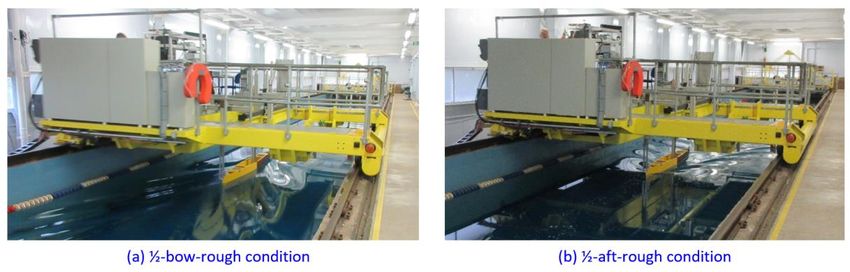
Hull and propeller roughness
Experiments to investigate roughness functions

 Flat plate in smooth condition

 Flat plate in rough condition

 13 13/05/2021
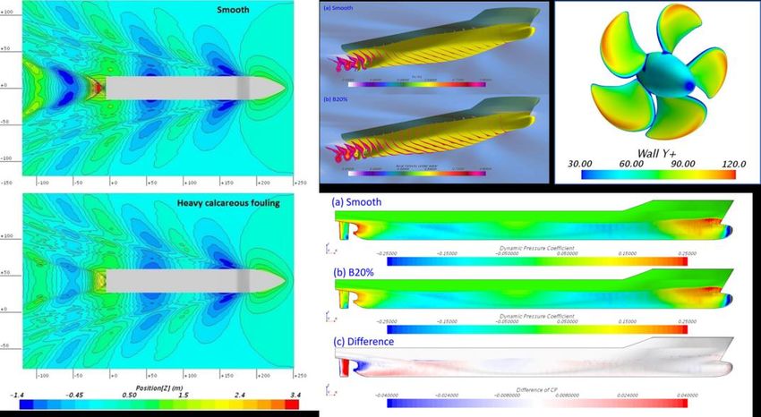
Hull and propeller roughness
Similarity law scaling and CFD

 14 13/05/2021
Hull and propeller roughness
• There is a need to adopt/develop new methods to predict the roughness effect of
 modern fouling-control coatings and marine biofouling on ship hydrodynamic
 performance. The similarity law scaling and CFD can be regarded as the most
 promising potential methods to predict such effects accurately. Both methods require
 the use of roughness functions of the surfaces in question.
• There is a need to generate a database of roughness functions of modern fouling-
 control coatings and surfaces representing heterogeneous biofouling accumulated on
 ship hulls and propellers.
• For this reason, it is recommended that standardized methods for roughness function
 determination should be adopted by researchers.
• It would, therefore, be useful to investigate the need for a guideline or procedure for the
 measurement of roughness functions for different surface finishes or conditions so that
 this information can be used for predicting the roughness corrections for both hull and
 propeller.

 15 13/05/2021
Quasi-steady propeller testing

Continue with monitoring the use of and, if possible, develop guidelines for quasi-steady
open water propeller and propulsion model tests.

 13/05/2021
Quasi-steady open water propeller tests
• A quasi-steady (QS) method is a promising technique • However, to develop the guidelines, limitation of the
 for time saving of POW test and propulsion test. MARIN application, e.g. how much wave making and/or
 has studied the method in the past and has shown a dynamic trim and sinkage are allowed, should be
 good correlation between QS tests and conventional clarified.
 ones. The last committee stated that validation by other
 than MARIN was a future issue. • It is recommended in the next term to conduct
 benchmark tests and validate the method by more
• During this term, HSVA presented the effectiveness of
 model basins.
 the QS resistance tests for more than 18 different ships
 in several different setups and confirmed good
 agreement with the conventional tests.

• The reliability of the QS method has been confirmed by
 both MARIN and HSVA, and it appears to be a viable
 alternative to conventional testing.

 Distribution of discrete deviations of the QS
 propulsion tests to the conventional tests

 17 13/05/2021
Rim driven thruster testing

Identify the need of the elaboration of the procedure concerning the rim drives model
testing and performance prediction.

 13/05/2021
Rim driven thruster testing
• Committee prepared a
 questionnaire on rim driven
 thruster testing
• Sent to 92 members of ITTC
• 13 completed responses
 received
• 6 organisations are actively
 involved in these type of devices

 19
Rim driven thruster testing

 20 13/05/2021
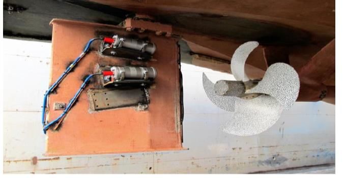
Rim driven thruster testing
• Lack of full scale test data
• Model tests carried out in towing tank or cavitation tunnel but special mounting arrangements
 and drive units required
• Thrust measured on whole unit using load cells or 6-component balance
• Torque either measured using load cells, 6-component balance, or derived from power
 • Friction in the gap between inner and outer ring needs to be accounted for
 • Torque on nozzle may not be negligible so needs to be measured

• Performance prediction can use standard ITTC method but needs corrections for gap friction.
 CFD commonly used for scaling.
• In summary there is no consistent approach to measurement or performance prediction so
 recommend that next RPC work towards a procedure.

 21 13/05/2021
Reynolds number effects on propulsor testing

Investigate the need of changing the standard criterion for Re in model tests of propulsors
as well as in the aspect of CFD validation.

 13/05/2021
Reynolds number effects on propulsor testing

• As described in the ITTC recommended procedures 7.5-02-03-02.1 Open Water
 Test and 7.5-02-03-01.4 1978 ITTC Performance Prediction Method, the minimum
 Re number must not be lower than 2×10⁵.
• There are some concerns about unstable propeller open water test data and about
 the applicability of corrections for low blade area ratio propellers or other
 unconventional propulsors, when below the critical Re number.
• The 28th ITTC Propulsion Committee suggested that it might be necessary to
 increase the minimum Re to at least 3×10⁵ to have enough margin to obtain
 reliable data. An additional literature review for the minimum Re is conducted
 during 29th ITTC term.

 23 13/05/2021
Reynolds number effects on propulsor testing

• From Kim et al. (1985), the difference of KT and KQ in
 Reynolds number are unstable at Re
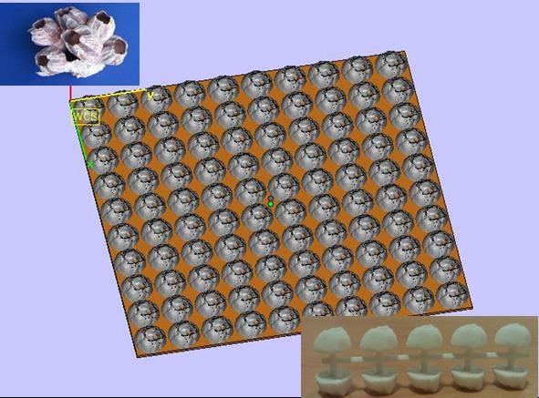
Reynolds number effects on propulsor testing

 • Hasuike et al (2017) presented the extensive oil flow visualization and numerical calculation for the scale effect of a series of propellers (27 in total)
 for a chemical tanker. Flow patterns in SPT condition at Re=2.7×10⁵ were similar (laminar and include laminar flow separation) to that in POT
 condition at Re= 3×10⁵ which was typical Reynolds number in SPT condition.
 • Baltazar et al (2019) presented the numerical prediction for an open water propeller (P0.7R /D=0.757 and Ae/A0=0.464) at different Reynolds
 numbers ranging from 104 to 107. From the flow pattern numerical results at Re=1×10⁵ and 5×10⁵ and KT KQ trend with Re ranging from 104 to 107,
 it seems that 5×10⁵ might be the minimum Re.
 • Yao (2019) presented the CFD investigation on the flow pattern of a PPTC propeller model (D=0.25m, P/D=1.635, Ae/A0=0.779) using commercial
 codes STAR-CCM+. The critical Re for such case is estimated to be around 3.48×10⁵.
 • Heinke et al (2019) investigated the Reynolds number influence on open water characteristics using four short chord length model propellers. For
 propeller A (D=0.239m, Ae/A0=0.418) and propeller B (D=0.239m, Ae/A0=0.444), the thrust coefficients are nearly constant, while the torque
 coefficient decreases linearly with rising Reynolds number if Re is above 5×10⁵. The ITTC 1978 correction method is applicable for consistent full
 scale propeller open water characteristics when the Re is above 5×10⁵.

flow visualization for POT (above) flow pattern for POT at different Re flow patterns on a PPTC variation of propeller coefficients of propeller A (left) and
and SPT (below) of Propeller C-2 Re=1×10⁵ (above) and propeller surface from Yao (2019) propeller B (right) with the Reynolds number from Heinke
(D=0.25m and Ae=0.38) from Re=5×10⁵ (below) from
Hasuike et al (2017) (2019)
 Baltazar et al (2019)

 25 13/05/2021
Reynolds number effects on propulsor testing
• The minimum Reynolds number (2×10⁵) in the present ITTC procedure is probably not sufficient for obtaining
 stable open water test data. This minimum Reynolds number generally ranges from 3×10⁵ to 5×10⁵ for different
 propeller types. This range might not be suitable for other propeller type, like CLT propeller and ducted propeller
 etc., which should be treated separately.

• One specific minimum Reynolds number which is applicable for all propeller type may not be possible. Each model
 basin is suggested to analyze the specific propeller case and choose the proper minimum Reynolds number
 especially for propulsion factors evaluation purpose.

• Careful attention should be paid for propeller open water RPM selection to achieve the similar transition or
 turbulent flow, not fully laminar flow pattern on the propeller model surface, and also for the proper propeller
 dynamometer range to reach the sufficient measurement resolution. A series of Reynolds number variation open
 water test or CFD simulation covering self propulsion propeller Reynolds number range is recommended for
 investigating the Reynolds number dependency.

• The ITTC procedures 7.5-02-03-01.4 1978 ITTC Performance Prediction Method and 7.5-02-03-02.1 Open water
 test procedures are recommended to be revised during 30th ITTC term.

 26 13/05/2021
Cooperation with other committees

Cooperate and exchange information with the Specialist Committee on Ships in Operation
at Sea regarding consequences of EEDI and with the Specialist Committee on Energy
Saving Methods.

 13/05/2021
Cooperation with the SC on Ships in Operation at Sea

• Recommended Procedure 7.5-02-03-01.4 “1978 ITTC Performance Prediction Method” was reviewed.
• The SOS committee found the inconsistency on a load variation test (LVT) in the current procedure. The
 figures, which are used for obtaining ξV in LVT, are derived from different data sets.
• The committee and the SOS calculated load variation factors for SSPA benchmark data. The load
 variation coefficients, ξP, ξN , ξV , derived from the same data set are almost same among all facilities.
• The committee has replaced Figure 4 and 5 in the current procedure with the new ones derived from the
 same dataset.
• For reference, the calculation detail for deriving the coefficients has been added as an appendix of the
 procedure.
 ∆ ∆
 = Comparison of load variation factors among SSPA, the SOS and the RPC
 0
 SSPA The SOS The RPC
 η ∆ ξP -0.19 -0.19 -0.19
 = ξn 0.25 0.25 0.25
 η 0 0
 ξV 0.33 0.34 0.32
 ∆ ∆
 =

 28 13/05/2021
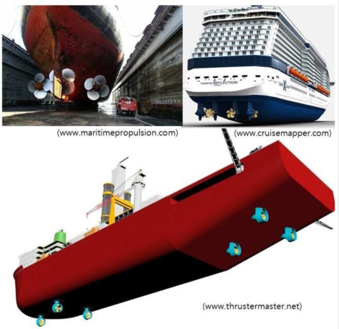
Validation of 7.5-02-03-01.7

Conduct the validation of the procedure 7.5-02-03-01.7, 1978 ITTC Performance
Prediction Method for Unequally Loaded, Multiple Propeller Vessels.

 13/05/2021
Validation of the procedure 7.5-02-03-01.7 • For the validation of this procedure, the detailed sea trial data for each shaft is required to be compared with model test prediction, but R&P committee cannot find any sea trial data in public domain or from contact with shipping company • Leaving this task as future work, R&P committee refined this procedure with sample data/graph/explanation to make this guide more comprehensive and practical • Procedure title changed: “Performance Prediction Method for Triple Shaft Vessels” “Performance Prediction Method for Unequally Loaded, Multiple Propeller Vessels”; This means more general description and definition are requested in the guide • Key point in the data analysis of ships having different loading of propeller due to different design and position is how the interaction effect between propeller and hull is evaluated. This is presented as “thrust deduction factor” of each propeller 30 13/05/2021
Validation of the procedure 7.5-02-03-01.7
• Thrust deduction factor is the ratio of the resistance and the
 (corresponding) thrust

• The question is how much (what portion of) resistance is
 burdened or distributed in each propeller and in other words
 “which propeller interacts more strongly with the hull?”

• Procedure 7.5-02-03-01.7 presents three steps to get the thrust
 deduction factor

• The ratio of resistance fraction of each propeller (not the absolute
 value) determines the thrust deduction factor by definition

• Three kind of load variation tests are requested: LVT1 for all
 propeller, LVT2 for center propeller and LVT3 for side propeller

 31 13/05/2021
Validation of the procedure 7.5-02-03-01.7
Sample calculation
• Model test data is provided for 1,500 passenger/1,600 lane meters RoPax ferry and it has one center propeller and two wing-side
 propeller

 ∆
 Load variation test for resistance fraction and the result of ( )
 ∆
• Model test prediction of each propeller: in this case, the center propeller has a higher value of thrust deduction factor and this means
 a stronger interaction of center propeller with hull

 32 13/05/2021
Influence of FD definition

Identify the influence of the new FD definition on power prediction.

 13/05/2021
Influence of the new FD definition
• ITTC 28th general conference accepted to adopt the
 new FD definition to enhance the accuracy of
 powering performance prediction adding CA in the
 formula, but did not provide any basis on whether it
 actually improved the accuracy

• From the year of 2008, the existing (old) △CF was
 divided into new △CF and CA (i.e, CTS includes new
 △CF and CA, but only (new) △CF was only included
 in FD calculation). This separation had been
 proposed from 19th ITTC because the existing △CF
 had been criticized for not properly reflecting the
 roughness effect of the hull and finally adopted at
 25th ITTC (2008)

• From the year of 2017, the new FD definition includes
 the CA and R&P committee is requested to identify
 the impact on the powering prediction

 34 13/05/2021
Influence of the new FD definition
• The actual value of FD in propulsion test with normal size of model ship is calculated. If we
 take the change from 27th to 28th, the typical value of change is as below;

 35 13/05/2021
Influence of the new FD definition
• A total of 31 cases from committee members were
 collected, covering a wide variety of ship types and speed.

• The influence of FD for large and high speed vessels is
 relatively limited.

• For small and slow vessels, the impact of FD definition
 change over power prediction is considerable and the
 propulsion efficiency change (EtaD) is about 1~2%.

• For the revolution of propeller, the impact of FD definition
 change is very limited around 0.2%.

• The new FD definition appears to make a very small
 difference to the powering prediction compared to previous
 definition.

 36 13/05/2021
Cavitation erosion modelling

Conduct a survey of cavitation erosion modeling and predicting methods.

 13/05/2021
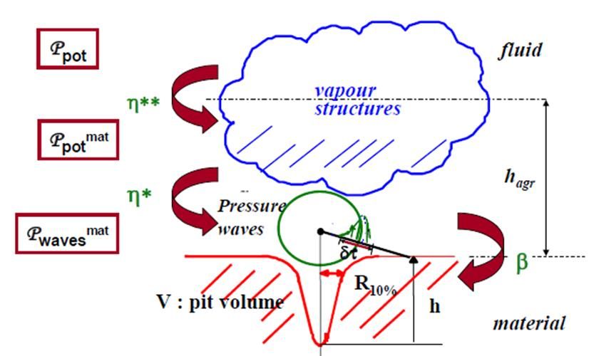
Cavitation erosion modelling

Cavitation erosion occurs when impulsive pressure from shock waves and/or microjets generated by
bubble collapse exceeds some material threshold, such as its yield stress.

 Model based on the energy balance Model based on the microjet formation

 38 13/05/2021
Cavitation erosion modelling

It is difficult to simulate the erosion numerically because a wide range of scales in time and space should
be treated in the calculation. Instead of direct simulations, erosion indicators derived from the
macroscopic flow solved using CFD calculation are usually used.

 Potential Power divided by cell volume

 = ∆ ∙ + ∙

 Void fraction
 Time derivative of pressure
 Time derivative of void fraction
 Difference between ambient pressure and vapor pressure

 Most indicators relate to pressure p, cavity volume V, void
 Illustration of time and length scales
 fraction α and their time derivatives.

 39 13/05/2021
Cavitation erosion modelling

 • To assess the cavitation erosion risk practically,
 various erosion indicators have been proposed.
 These indicators are helpful for propeller designers
 to predict potential erosion areas and locations.

 • However, it is unclear whether they always give
 reasonable predictions against various kinds of
 cavitation pattern. To evaluate the cavitation
 aggressiveness, some threshold for the indicator is
Hasuike et al. (2009) Usta et al. (2017) required. Although they influence much on the
 erosion prediction, how to determine it is also
 unclear.

 • Cavitation erosion modelling is a rapidly developing
 topic, and further developments should continue to
 be monitored, and updates to procedures should be
 considered in future.

 Melissaris et al. (2019)

 40 13/05/2021
Propeller performance in waves

Investigate and describe a propulsor performance in waves, and discuss the scale effects
on its modelling.

 13/05/2021
Propeller Performance in Waves

• A literature study was undertaken to investigate and identify the influences of operating propellers in waves.

• The influences on the propeller inflow are broken down into two categories; wave dynamics, and induced
 flows from ship motions in waves.

• Influences were identified as added resistance, temporal and spatial variation of inflow wakes, ventilation,
 shaft speed variation affecting thrust, torque, efficiency, cavitation, and pressure pulses.

 h Propeller
 performance
 Kq as a function
 of wave
 Kt oscillation
 from
 h McCarthy et
 al (1961)

 Calm water and wave agreement
 considering propeller inflow speed from
 McCarthy et al (1961)

 42 13/05/2021
Propeller Performance in Waves

• Fluctuations in the open water thrust and torque in waves are in
 good agreement with the calm-water uniform-flow performance
 curves for the propeller (McCarthy, 1961 and Taskar et al, 2016).
 => Efficiency is primarily affected by the average change in
 wake fraction and not much by wake distribution.
 Calm water and wave
 agreement considering
• For the low frequencies of encounter of a propeller and waves, propeller inflow speed
 unsteady effects may be neglected. from Taskar et al (2016)

• Tokgoz et al (2017) investigated depth of propeller immersion in
 waves. Due to wave orbital velocities, the minimum thrust is
 achieved when the wave crest is at the propeller plane.

• Ventilation was shown to significantly affect the trend of thrust
 fluctuations where the maximum value of thrust occurs in the Correlation of Kt from
 waves and calm water and
 wave crest while the minimum values of thrust occur in the influence of ventilation for
 wave trough when ventilation occurs. KVLCC2 propeller at
 J=0.5 from Tokgoz et al
 (2017)

 43 13/05/2021
Propeller Performance in Waves

• Tokgoz et al (2017) computed the KVLCC2 in waves and showed that when surge is
 essentially zero, the mean values of the EFD and CFD results are comparable. When the
 ship surges forward the thrust is not comparable.

• Taskar et al (2017) show that the mean wake fluctuations due to the wave orbital velocities
 Surging influence
 are relatively constant and greater than that due to surge regardless of the wavelengths. on thrust in waves
 The mean change in wake is more significant at low ship speeds. from Tokgoz (2017)
 Region A negative
• Hsin, Ching-Yeh et al (2016) concluded that the unsteady flow effects due to the ship wake surge, Region B
 relatively zero surge
 is more important than that due to the ship motions.

• Taskar et al (2015) showed that cavitation and pressure pulses are directly related to wake
 distribution, and they depend less on average wake fluctuations. The relative stern motion
 was only shown to affect the range of Cpmin and not the angle of attack.

• Taskar et al (2016) additionally revealed that the blade root circulation in short waves was
 always greater than calm water and generally higher for all other wave conditions.

• Taskar et al (2017) found that contrary to the expectation of less hull wake influences for a
 twin-screw ship, both the cavitation and pressure pulses increased remarkably due to the
 effect of waves, as did the cavitation volumes.
 Wake and relative stern motion influence
 on angle of attack and Cpmin from Taskar
 et al (2015)

 44 13/05/2021
Recommendations

 13/05/2021
Recommendations
• Adopt the updated procedures: • Adopt the new procedure on “Wave
 • 7.5-02-02-01 profile measurement and wave pattern
 • 7.5-02-02-02 resistance analysis”
 • 7.5-02-02-02.1
 • 7.5-02-02-02.2
 • 7.5-02-03-01.1
 • 7.5-02-03-01.3
 • 7.5-02-03-01.4
 • 7.5-02-03-01.7
 • 7.5-02-03-02.1
 • 7.5-03-01-01
 • 7.5-03-01-02
 • 7.5-03-02-02
 • 7.5-03-02-04

 46 13/05/2021
Recommendations
• Develop new methods to predict the roughness effect of modern • Continue monitoring developments in cavitation erosion prediction
 fouling-control coatings and marine biofouling on ship hydrodynamic
 • Carry out a benchmark study on propeller performance scaling using
 performance.
 CFD

• Develop a guideline or procedure for the measurement of roughness • The procedures on CFD verification and validation should be reviewed
 functions for different surface finishes. and updated to reflect current best practice

• Continue attempting to obtain full scale data on multiple propeller • The requirements for testing and numerical evaluation of high speed
 vessels vessels should be investigated

 • The use of CFD to predict full scale ship performance and the need for
• Continue trying to obtain full scale data on podded propulsors
 validation at full scale evaluated

• Develop a guideline/procedure on quasi-steady propulsion testing • The measurement and prediction of breaking waves should be further
 investigated
• Develop a guideline/procedure for rim driven thruster testing and
 performance prediction • Continue to monitor developments in hull and propeller model
 manufacturing
• The ITTC procedures 7.5-02-03-01.4 and 7.5-02-03-02.1 are
 • Develop guidelines for model testing of low skin friction coatings and
 recommended to be revised during 30th ITTC term to update the
 air lubrication systems.
 minimum Reynolds number for propulsion testing.

 47 13/05/2021
You can also read