Technology Development Plan - August 2019 - Astrophysics Science Division
←
→
Page content transcription
If your browser does not render page correctly, please read the page content below
Technology
Development Plan
August 2019
Contents
1 - INTRODUCTION...................................................................................................................................................................................................1
2 - CRYOCOOLERS.....................................................................................................................................................................................................2
    2.1 Cryocoolers to Achieve 4.5 K...........................................................................................................................................................................2
        2.1.1 Cryocooler Requirements......................................................................................................................................................................2
        2.1.2 Cryocooler State-of-the-Art.................................................................................................................................................................3
        2.1.3 Advancements Planned to Reach TRL 5 and 6.....................................................................................................................................4
    2.2 Sub-Kelvin Cooling..........................................................................................................................................................................................5
        2.2.1 Sub-Kelvin Cooling Requirements........................................................................................................................................................5
        2.2.2 Sub-Kelvin State-of-the-Art.................................................................................................................................................................6
        2.2.3 Advancements Planned to Reach TRL 5 and 6.....................................................................................................................................6
    2.3 Cryocooler Schedule and Cost........................................................................................................................................................................7
3 - FAR-INFRARED DETECTORS FOR OSS AND FIP................................................................................................................................................8
    3.1 Transition-Edge-Sensed (TES) Bolometers..................................................................................................................................................11
        3.1.1 TES Foundations..................................................................................................................................................................................11
        3.1.2 TES State-of-the-Art...........................................................................................................................................................................12
        3.1.3 Theoretical Predictions for Current TES Technologies..........................................................................................................................13
        3.1.4 TES Challenges.....................................................................................................................................................................................14
        3.1.5 TES Development Plan........................................................................................................................................................................14
    3.2 Cryogenic Readout Electronics for TES bolometers......................................................................................................................................15
        3.2.1 Direct Microwave Multiplexing...........................................................................................................................................................15
        3.2.2 Hybridized Time-Frequency Division Multiplexing with Microwave Multiplexing...........................................................................16
        3.2.3 Code Division Multiplexing and Frequency Division Multiplexing Variants.......................................................................................17
    3.3 Kinetic Inductance Detectors........................................................................................................................................................................18
        3.3.1 Foundations: Physics of Photon Detection.........................................................................................................................................18
        3.3.2 KID State-of-the-Art...........................................................................................................................................................................19
        3.3.3 KID Challenges.....................................................................................................................................................................................20
        3.3.4 KID Development Plan........................................................................................................................................................................23
    3.4 Quantum Capacitiance Detector...................................................................................................................................................................25
    3.5 Warm Readout Electronics............................................................................................................................................................................26
        3.5.1 Power vs. TRL.......................................................................................................................................................................................27
    3.6 Schedule for FIR Array Development, Down Select Strategy, and Cost Estimate........................................................................................29
4 - Mid-Infrared Arrays............................................................................................................................................................................................30
    4.1 Mid-IR Array Requirements..........................................................................................................................................................................30
    4.2 Mid-IR Detector Technology State-of-the-Art.............................................................................................................................................30
    4.3 Mid-IR Array Challenges...............................................................................................................................................................................32
    4.4 HgCdTe Detector Array Technology Development........................................................................................................................................32
        4.4.1 HgCdTe Detector Development Plan...................................................................................................................................................33
        4.4.2 HgCdTe Detector Manufacturing.........................................................................................................................................................35
        4.5 Si:As Detector Development Plan..........................................................................................................................................................37
        4.6 HgCdTe Detector Testing.........................................................................................................................................................................38
        4.7 TES Development Plan...........................................................................................................................................................................39

From First Light to Life                                                                                                                                                                                    Vol 2-1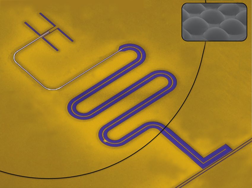
4.8 Schedule for MIR array development and Down Select Strategy................................................................................................................40
5 - Cost Summary....................................................................................................................................................................................................40
APPENDICES
    Appendix A: TES Detector Development Labor Plan and Budget
    Appendix B: MKID Detector Development Labor Plan and Budget
    Appendix C: Mid-IR Detector Development Labor Plan and Budget: HgCdTe and TES Bolometers
    Appendix D: Origins Space Telescope Sub-Kelvin Cryocooler Technology Development
    Appendix E: Far-IR Detector Readout Electronics for the Origins Space Telescope
    Acronyms and Definitions
    References

From First Light to Life                                                                                                                                                                                     Vol 2-2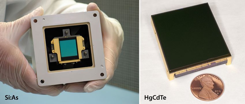
1 - INTRODUCTION                                                               FAR-IR Detector Requirements
   The Origin s Space Telescope’s (Origins) signifi-                                   (Photon Background NEP)
cant improvement over the scientific capabilities
of prior infrared missions is based on its cold tele-                                           Spectrometer on Warm Tel.
scope (4.5 K) combined with low-noise far-IR de-                                                e.g. balloon: Ttel=270, ε=2%, R=1000
tectors and ultra-stable mid-IR detectors. A small            10–17

number of new technologies will enable Origins

                                                                                                        Photon Noise Equiv. Power (W Hz–1/2)
to approach the fundamental sensitivity limit im-
posed by the natural sky background and deliver                        Origins Camera (FIP)
                                                              10–18    Ttel=4.5K, ε=2%, R=3, 2x oversampling
groundbreaking science. This report describes a
robust plan to mature the Origins mission-en-
                                                                     AI KID, optical
abling technology from current state-of-the-art
(SOA) to Technology Readiness Level (TRL) 5 by                10–19
                                                                                        TES bolometer (electrical)         R=300
2025 and to TRL 6 by mission PDR. Entry TRLs
                                                                             Origins Spec (OSS)                                 R=100,000
corresponding to today’s SOA are 3 or 4, depend-                             Ttel=4.5K, ε=2%
ing on the technology in question. Potential mis-
                                                              10–20
sion-enhancing technology is not described in this
report, except where the enhancement naturally
extends an effort to develop enabling technology.                                            100                                   1000
Mission enhancing technologies include lighter                                               Wavelength (µm)
weight optics, smaller far IR-spectrometers, and                                                                                     OriginsFC1

improvements to heterodyne detectors.                  Figure 1: Sensitivity (i.e., NEP) requirements for far-IR instrumen-
   Cryocooler advancement is needed to cool the tation. Curves show the photon shot noise – improving detectors
telescope to 4.5 K and the detectors in the far-infra- beyond this produces diminishing gains. The most demanding ap-
red instruments to sub-Kelvin temperatures. Cool- plication is the Origins spectrometer (OSS), for which the photon
ing the entire observatory reduces its self-emission, NEP is as low as 3x10 W Hz . Horizontal lines show published
                                                                                   -20        -1/2

and cooling the far-infrared detectors reduces their measurements        (aluminum KID from the SRON group, TES bolome-
                                                       ters at 1x10-19 W Hz-1/2 were measured at JPL and SRON).
noise, and both are required to reach astronomical
background-limited performance.
   Figure 1 shows the detector sensitivity needed to reach natural background-limited performance,
expressed as Noise Equivalent Power (NEP). The NEP required for imaging is ~3 x 10-19 W Hz-1/2,
whereas the NEP needed for the far-infrared spectrometer OSS with its spectral resolution of R=300
is 3 x 10-20 W Hz-1/2.
Table 1: Detector characteristics for Origins instruments
                    Temp           λmin         λmax                                                              Saturation
       Inst.                                               R=λ/Δλ              Npix                    Sensitivity                              Notes
                     (K)          (μm)         (μm)                                                                  Limits
                                                                                                                50 μm: 1 Jy    2 bands, total power mode and
FIP1                50 mK           50          250            3         6,500 NEP=3 x 10-19 (W/Hz1/2)          250 μm: 5 Jy polarimetry mode
                                                                                                                5 Jy @ 128 μm 6 bands R~4 x 10⁴ FTS mode
OSS1                50 mK           25          588          200      104 6 arrays NEP=3 x 10-20 (W/Hz1/2)      for R=300
                                                                                                                               Detector stability limiting (5 ppm
MISC Transit 50 mK                                         Up to 295 104 or 4 x 10⁶ NEP=3    x 10 (W/Hz ) 5 ppm K~3.0 mag
                                                                                                 -18      1/2
                                   2.8           20                                                             30 Jy @ 3.3 μm aimed  for the short and mid wave-
Spectrometer2 30K                                                                   stability over a few hours                 length band)
 1
  Superconducting detectors will be used for the direct detection instruments (FIP, OSS) that operate at wavelengths beyond 25 μm. These instruments need arrays with ~104 pixels, which could be
 achieved by use of a mosaic of arrays with several 103 pixels. This method has been demonstrated in existing FIR instruments (e.g., SOFIA/HAWC+). For OSS, each detector couples to an R=300 band at
 the focus of the grating modules. This sets the sensitivity requirement; the medium- high-resolution modes use the same grating just with an FTS inserted in front.
 2
  The baseline detector technology for the long wavelengths channel of the mid-IR transit spectrometer will be arsenic-doped silicon impurity band conduction (Si:As IBC) detectors. These are being
 used in JWST/MIRI (Ressler et al., 2008) in a 1 k x 1 k format. For the transit spectrometer’s two shorter wavelength channels, the baseline detector technology is HgCdTe, which will be developed to
 provide the required performance parameters. TES detectors are also investigated for MISC-T stability requirements.

From First Light to Life                                                                                                                                                                          Vol 2-1
While the noise requirements for the Transit Spectrometer’s mid-IR detectors are nominally not a
challenge (the required NEP is ~3 x 10-18 W Hz-1/2, which is routinely achieved with existing FIR de-
tectors), stability over several hours must be addressed to meet Origins requirements. Origins’ required
stability over several hours of uninterrupted source monitoring is 5 ppm.
   Table 1 lists the detector requirements for Origins instruments, including wavelength range, number
of pixels, and sensitivity as measured by NEP.
Managing the Technology Development Program
   During the technology development program, a dedicated technology Program Manager will hold
an overall 25% contingency to be applied to critical needs for any of the technology development
efforts. The Program Manager is also in charge of the technology review processes and the technology
down-selection process. The Origins Program Office will also have a systems engineer who will assure
alignment of the Origins requirements with the technological developments. This organizational struc-
ture will continue from the beginning of pre-Phase A through Phase A.
   As risk reduction, the individual technology development plans discussed below include funded
schedule contingency. As further risk mitigation, different technologies are being developed in parallel
for far-IR detectors, mid-IR detectors, and 4.5 K cryocoolers. The sub-K cooler development reaches
TRL 6 before Phase A, leaving significant schedule margin.
   This document describes the cost associated with maturing the technology during pre-Phase A.
Phase A costs are accounted for in the Origins Cost Report. The complete mission lifecycle cost of the
Origins Space Telescope is summarized in section 4.5 of the Origins Mission Concept Study Report.
   Note that for the schedules shown in this volume, we have defined Program Year which is defined
as starting in the middle of the calendar year. We have assumed that the Pre-Phase A activities start in
mid 2021, i.e., the beginning of PY 2021.
2 - CRYOCOOLERS
  Origins requires 4.5 K mechanical coolers for all instruments and telescope, and sub-Kelvin coolers
for the OSS and FIP instruments. If MISC-T selects bolometers for the long wavelength mid IR chan-
nel, then another sub-Kelvin cooler will be required.
2.1 Cryocoolers to Achieve 4.5 K
2.1.1 Cryocooler Requirements
   Taking advantage of radiation to deep space can enable achieving low temperatures. However, due
to the T4 decrease in cooling power per area – and parasitic heat from the spacecraft, Earth, and Sun –
radiators colder than ~30 K are not practical. In the past, the InfraRed Astronomy Satellite (IRAS), the
Cosmic Background Explorer (COBE), the Infrared Space Observatory (ISO), Spitzer, and the Herschel
instruments used liquid helium to cool to
sen as the base temperature to limit the in-band                       Zodi@Ecliptic Pole + Telescope Flux
emission from the telescope. While a temperature
                                                             10-11  Zodi+(Toptics = 8.0 K)           Tele. Emissivity = 0.05
lower than the cosmic microwave background at

                                                                   Zodi + Telescope Flux (W/cm2/µm/sr)
                                                                    Zodi+(Toptics = 5.0 K)      Min. = 5.00E-15 at 393.3µm
2.7 K provides the least noise, for low emissivity                  Zodi+(Toptics = 4.5 K)
optics, 4.5 K represents a reasonable compromise,                   Zodi+(Toptics = 4.0 K)
                                                             10-12          Zodi Alone
allowing use of some existing cryocoolers, as well
as limiting input power to the cryocoolers. See
Figure 2 for a comparison of telescope emission              10-13
for various temperatures and sky background.
   Origins is designed with high thermal conduc-
                                                             10-14
tance materials in low-temperature regions. Con-
sequently, the 4.5 K, 20 K, and 35 K regions are
all nearly isothermal. Cooling these areas at one                    100         200       300       400          500

location produces only small gradients. Therefore,                                   Wavelength (µm)
                                                                                                                         OriginsFT2
concepts such as broad area cooling are not re- Figure 2: A comparison of telescope emission (effective emissivity
quired. What is required, however, is a scheme to = 0.05) vs. sky backgound in the mid to far infrared.
transfer relatively-cold fluid where it is produced
(e.g., at the spacecraft) to where it is needed at the telescope, instruments, and surrounding structure.
Fortunately, the scheme used by the James Webb Space Telescope (JWST)/Mid InfraRed Instrument
(MIRI) cooler also works for Origins, and the Origins system has been modeled after it. Two of the five
cooler concepts need some method to mimic this (e.g., by providing a separate circulating loop). Soft
mounted compressors of the type for the MIRI cooler have been shown to produce exported vibration
~ 0.1 N. Origins performed a rough simulation of the effect on the telescope, using 4 simultaneously
operating coolers each producing this level of vibration. The results indicated that the stability require-
ments for the most sensitive instrument were met by a factor of more than 5. See Section 2.8 of the
main report for details.
2.1.2 Cryocooler State-of-the-Art
   Mechanical cryocoolers at TRL 7+ include Planck (Planck Collaboration, 2011), JWST/MIRI
(Petach, 2014), and Hitomi (ASTRO-H) (Fujimoto, 2018). Note that while the quoted performance
of the JT cryocooler on Hitomi was 4.5 K, the actual cooler temperature under full load was 4.3-4.4
K, so a considerable margin exists on achieving the telescope temperature of 4.5 K. Domestic coolers
that could achieve 4.5 K are considered to be TRL 4-5, having been demonstrated as a system in a lab-
oratory environment under NASA’s Advanced Cryocooler Technology Development Program (ACT-
DP) (Ross, 2006; Figure 3) or are a variant of a high TRL cooler (JWST/MIRI). The JWST/MIRI
cryocooler engineering unit was tested with a simple substitution of the rare isotope 3He for the typical
4
  He, which produced significant cooling at temperatures below 4.5 K (Petach, private communica-
tion). Mechanical cryocoolers for higher temperatures have already demonstrated impressive on-orbit
reliability (Ross, 2007; Figure 4). The moving components of a 4.5 K cooler are similar (expanders)
or are exactly the same (compressors) as those that have flown. Further development of these coolers
to maximize cooling power per input power (
NGAS JWST/MIRI                  Ball 10 K                                 Lockheed ACTDP            SHI Hitomi/SXS

                                                                                            Creare

                                                                                                                               OriginsFT3

Figure 3: Five vendors have developed cryocoolers that have reached TRL 4+ and need only small improvements to meet the Origins 4.5 K
cooling requirements.
2.1.3 Advancements Planned to Reach TRL 5 and 6.
   The TRL 7 JWST/MIRI cryocooler is designed to cool a primary load at 6.2 K and an intercept load
at 18 K. It does this using a precooled helium Joule Thompson loop that compresses 4He from 4 to
12 bar, precools it to 18 K with a three-stage pulse tube cryocooler, then circulates it to a remote heat
intercept at 18 K and an isenthalpic expander that provides cooling at 6.2 K. The only change required
to lower the temperature to 4.5 K is to lower the return pressure from 4 bar to 1 bar. To maintain the
required mass flow, the compressor swept volume must be increased to accommodate the lower density
of the lower pressure helium, and the pressure ratio must be increased to maintain the pressure drop.
This can be achieved by upgrading the JT compressor used in the MIRI cooler. One way this can be
done is by augmenting the existing MIRI JT compressor with a second JT compressor of the same
design but with larger pistons to act as the first stage in a two-stage compressor.
   The Lockheed four-stage pulse tube cryocooler has demonstrated the required heat removal at the
temperatures required for Origins in a TRL 4 design (Olson, 2005). However, for Origins, 4.5 K is
required in a location that is remote from the compressor. This will require development of a separate
4.5 K cooling loop. This could be realized using a HST/NICMOS cooling loop driven by a “fan.”
   The Ball Aerospace (Ball) 4.5 K cooler design uses a similar architecture to the NGAS JWST/MIRI
cryocooler with a Stirling-type displacer (rather than a pulse tube) and a JT with a long loop for remote
cooling. The Ball design lacks a system-level demonstration to reach TRL 5 (Glaister, 2007).
   Creare is currently funded through an SBIR Phase II contract to demonstrate a 4.5 K turbo-expand-
er. This will demonstrate a TRL 4 component of the system and is the lowest TRL component of the
Creare design. During Origins Pre-Phase A funding the turbo-expander will be combined with other
components (2 other turbo-expanders, three recuperators and compressors) to attain TRL 5. A TRL-6
version will be designed as an ETU of the Origins flight coolers.
   Creare is developing a 4.5 K stage for its miniature turbine reverse-Brayton cryocoolers under SBIR
funding. This expansion stage is similar to the one used for a single stage cooler flown on HST/NIC-
MOS and the two-stage 10 K design currently at TRL 5.

From First Light to Life                                                                                                       Vol 2-4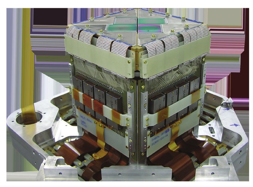
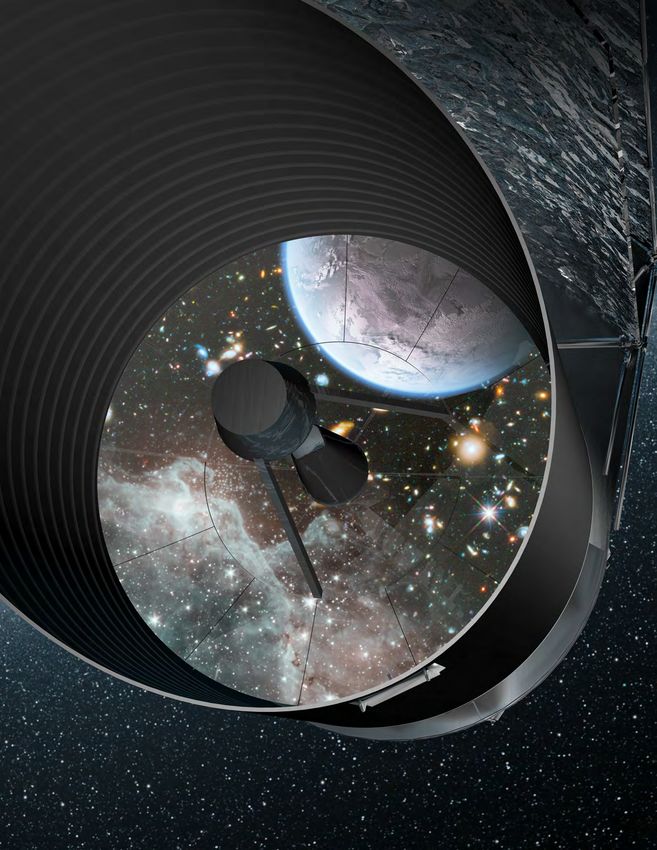
Recent Long-Life Space Cryocooler
                                    Flight Operating Experience as of May 2016
                           Cooler/Mission             Hours/Unit                  Comments
       Air Liquide Turbo Brayton (ISS MELFI 190K)        85,600    Turn on 7/06, Ongoing, No degradation
       Ball Aerospace Stirling
           HIRDLS (60K 1-stage Stirling)                 83,800    8/04 thru 3/14, Instr. failed 2009; Data turned off 3/14
           TIRS cooler (35K two-stag Stirling)           27,900    Turn on 3/6/13, Ongoing, No degradation
       Creare Turbo Brayton (77K NICMOS)                 57,000    3/02 thru 10/09, Off, Coupling to Load failed
       Fujitsu Stirling (ASTER 80K TIR system(          141,700    Turn on 3/00, Ongoing, No degradation
       JPL Sorption (PLANCK 18K JT (Prime & Bkup))       27,500    FM1 (8/10-10/13 EOM); FM2 failed at 10,500 h                   Creare NICMOS
       Mitsubishi Stirling (ASTER 77K SWIR system)      137,500    Turn on 3/00, Ongoing, Load off at 71,000 h
       NGAS (TRW) Coolers
           CX (150K Mini PT (2 units))                  161,600    Turn on 2/98, Ongoing, No degradation
           HTSSE-2 (80K mini Stirling)                   24,000    3/99 thru 3/02, Mission End, No degradation
           MTI (60K 6020 10cc PT)                       141,600    Turn on 3/00, Ongoing, No degradation                       NGAS (TRW) Mini PT
           Hyperion (110K Mini PT)                      133,600    Turn on 12/00, Ongoing, No degradation
           SABER on TIMED (75 Mini PT)                  129,600    Turn on 1/02, Ongoing, No degradation
           AIRS (55K 10cc PT (2 units))                 121,600    Turn on 6/02, Ongoing, No degradation
           TES (60K 10cc PT (2 units))                  102,600    Turn on 8/04, Ongoing, No degradation
           JAMI (65K HEC PT (2 units))                   91,000    4/05 to 12/15, Mission End, No degradation
           GOSAT/IBUKI (60K HEC PT)                      63,300    Turn on 2/09, Ongoing, No degradation
           STSS (Mini PT (4 units))                      52,800    Turn on 4/10, Ongoing, No degradation                      NGAS (TRW) AIRS PT
           OCO-2 (HEC PT)                                14,900    Turn on 8/14, Ongoing, No degradation
           Himawari-8 (65K HEC PT (2 units))             12,800    Turn on 12/14, Ongoign, No degradation                NGAS (TRW)
       Oxford/BAe/MMS/Astrium/Airbus Stirling                                                                              HEC PT
          ISAMS (80K Oxford/RAL)                         15,800    10/91 thru 7/92, Instrument failed
          HTSSE-2 (80K BAe)                              24,000    3/99 thru 3/02, Mission End, No degradation
          MOPITT (50-80K BAe (2 units))                 138,600    Turn on 3/00, lost one disp. at 10,300 h
          ODIN (50-80K Astrium (1 unit))                132,600    Turn on 3/01, Ongoing, No degradation
          AATSR on ERS-1 (50-80K Astrium (2 units))      88,200    3/02 to 4/12, No degradation, Satellite failed
          MIPAS on ERS-1 (50-80K Astrium (2 units))      88,200    3/02 to 4/12, No degradation, Satellite failed
          INTEGRAL (50-80K Astrium (4 units))           118,700    Turn on 10/02, Ongoing, No degradation
          Helios 2A (50-80K Astrium (2 units))           96,600    Turn on 4/05, Ongoing, No degradation
          Helios 2B (50-80K Astrium (2 units))           58,800    Turn on 4/10, Ongoing, No degradation
          SLSTR (50-80K Airbus (2 units))                 1,400    Turn on 3/16, Ongoing, No degradation
          Planck (4K JT using 2 Astrium Comp.)           38,500    5/09 thru 10/13, Mission End, No degradation        Astrium (BAe)
       Raytheon ISSC Stirling (STSS (2 units))           52,800    Turn on 4/10, Ongoing, No degradation                  50-80K
       Rutherford Appleton Lab (RAL)
           ASTR 1 on ERS-1 (80K Integral Stirling)       75,300    7/91 thru 3/00, Satellite failed                                              RALATSR
           ASTR 2 on ERS-2 (80K Integral Stirling)      112,000    4/95 thru 2/08, Instrument failed
       Sumitomo Stirling Coolers
           Suzaku (100K 1-stg)                           59,300    7/05 thru 4/12, Mission End, No degradation
           Akari (20K 2-stg (2 units))                   39,000    2/06 to 11/11 EOM, 1 Degr., 2nd failed at 13 kh
           Kaguya GRS (70K 1-stg)                        14,600    10/07 thru 6/09, Mission End, No degradation               Sunpower
           JEM/SMILES on ISS (4.5K JT)                    4,500    Turn on 10/09, Could not restart at 4,500 h                 RHESSI
       Sunpower Stirling
           RHESSI (75K Cryotel)                         124,600    Turn on 2/02, Ongoing, Modest degradation
           CHIRP (CryoTel CT-F)                          19,700    9/11 to 12/13, Mission End, No degradation
                                                                                                                                       Ross 05/18/16 OriginsFT4
Figure 4: On orbit mechanical cooler lifetimes. Almost all cryocoolers have continued to operate normally until turned off at the end of
instrument life. (Ross, 2007, updated). Note that there are 8766 hours in one year.
  The Sumitomo Heavy Industries (SHI) 4.5 K cryocooler flown on Hitomi had a lifetime goal of 5
years. Lifetime is expected to be limited by bearing friction and contamination. Reliability and lifetime
will be improved by using a non-contacting suspension system (similar to displacers) and by improving
the cleanliness of the critical internal parts and working fluid. This will extend expected life from 5 to
10 or more years. This development is in progress at SHI.
2.2 Sub-Kelvin Cooling
2.2.1 Sub-Kelvin Cooling Requirements
  The FIP instrument requires: 3 µW of cooling at 50 mK plus 125 µW at 0.6 K for a heat rejection
temperature at 4.5 K with a heat rejected of 4 mW average.

From First Light to Life                                                                                                                                  Vol 2-5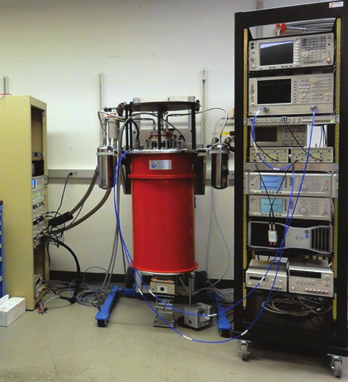
The OSS instrument requires: 3 µW of cooling at 50 mK plus 125 µW at 0.6 K plus 500 µW at 1.6 K
for heat rejection temperature of 4.5 K and a heat reject power of 8 mW average. These cooling powers
are the current best estimates (CBE) from the up-scoped design for these instruments (Origins Mission
Concept Study Report, Section 3). The cooling required is over and above any internal sub-Kelvin cooler
requirements and inefficiencies. For the baseline designs (Origins Mission Concept Study Report, Section
3), the requirement for low temperature heat lift will be lowered by almost a factor of 2. It is also required
that the sub-Kelvin cooler capability would provide a factor of 2 margin for the baseline design. In other
words the sub-Kelvin coolers must be capable of providing 6 µW of cooling at 50 mK and 250 µW of
cooling at 0.6 K. Superconducting detectors and their readout systems are very sensitive to small/time
varying magnetic fields. Typically, a detector package will provide its own shielding to deal with external
fields on the order of 30 µT, so the magnetic field generated by the sub-Kelvin cooler must be
Continuous      Second             Continuous                  Fourth                     Fifth
                    First stage      stage             Third stage                  stage                     stage

    0.05 K                                                                       .54 - 1.5 K                                           4.5 K
     Heat              .05 K      .045 - .3 K                                     27 - 1.5 K              1.35 - 4.6 K
     Load                                                                                                                              Heat
                                                                                                                                       Sink

                                                           0.6 K
                                                                                     magnet           salt pill          heat switch
                                                                                                                                          OriginsF156

Figure 6: A schematic representation of the FIP and OSS CADRs. The ADR stages are synchronized to move heat from the 50 mK and 0.6 K
stages to the 4.5 K stage, where it is lifted by the 4.5 K cryocooler(s). Salt pill operating temperature range is indicated. The average cooling
power for each continuous stage and heat rejection to the sink are indicated in red, as they called out in instrument requirements.
provide additional cooling at higher temperatures. The design includes a surrounding magnetic shield,
resulting in less than 1 µT external field. The large gray pill-shaped structure in Figure 5 is the notional
magnetic shield and will easily meet the requirement.
   The CADR design is aided by software that accurately simulates its operation. This allows users to
vary salt pill sizes, materials, operating temperatures, magnetic field strengths, and heat switch conduc-
tances to approach an optimum design. The CADR for the Origins/FIP instrument, shown schemat-
ically in Figure 6, will include five stages made of elements nearly identical to those used in the new
2019 CADR. The CADR for the Origins/OSS instrument will have an additional two stages, similar to
stages 4 and 5 (not shown), to provide 1 mW (factor of 2 higher than requirement) of cooling at 1.3 K.
The first and third stages will remain continuously at 0.05 and 0.6 K, respectively. The fourth stage
cools to absorb heat from the second and third stages on alternate cycles. Each stage cycles between
maximum and minimum magnetic field in ~20-30 min.
   The five Origins ADR stages use two different magnetocaloric materials: gadolinium-lithium-fluo-
ride (GLF) and chrome-potassium-alum (CPA). Performance of these materials in an actual ADR are
well understood and accurately modeled. Based on the design study, the two cooling power values are
100% higher than the corresponding heat load predictions.
   The flight control electronics for this ADR is based on the flight-proven Hitomi ADR controller,
and has achieved TRL 6 by employing the same cards used in the Hitomi flight unit (Figure 4).
   The CADR components are modular, so the CBE design (Figure 4) may be easily rearranged to better
conform with volume constraints. Heat straps shown exiting the magnetic shield are notional and a pen-
etration that prevents fringing magnetic field from reaching the outside of the shield is underway. This
notional CADR design has an estimated mass of 21 kg, including 9 kg for the outer magnetic shield.
   The electronics box (Figure 5) includes eight thermometry channels per card, with adjustable exci-
tation and resolution that provides complete temperature readout for the host instrument, as well as
CADR control.
2.3 Cryocooler Schedule and Cost
  Top-level schedules for the 4.5 K cryocooler and the sub-Kelvin cooler technology development are
provided Figures 7a and 7b, respectively. We expect to perform Task 1 in Figure 7a similarly to the way
the Advanced Cryocooler Technology Development Program (ACTDP) was executed, with several
vendors sharing a total funding of about $10M per year over a 4-year span. This effort will conclude
in 2025 with a single vendor selected to qualify the TRL 5 cooler to TRL 6 during Phase A at a cost
of $2.5M per year.

From First Light to Life                                                                                                                         Vol 2-7
KDP A KDP B
Pre-Phase A Phase A
Tasks PY21 PY22 PY23 PY24 PY25 PY26 PY27 Success Criteria
Q1 Q2 Q3 Q4 Q1 Q2 Q3 Q4 Q1 Q2 Q3 Q4 Q1 Q2 Q3 Q4 Q1 Q2 Q3 Q4 Q1 Q2 Q3 Q4 Q1
Tasks by company
Ball Aerospace
Task 1 - SC235E pre-cooler update and fabrication Pass peer review
Task 2 - J-T cooler update and fabrication Pass peer review
Task 3 - CCE Update Pass peer review
Task 4 - cryocooler soft mount design update TRL 5 Pass peer review
Task 5 - TVAC and performance testing Pass Project review
Task 6 - Performance update and validation Pass peer review
Task 7 - CCE brassboard fabrication Pass peer review
Task - TVAC performance test and verification Pass Project review
Creare, LLC
Task 1 - Mature lowest TRL component to TRL 4 (in progress) TRL 5 Pass peer review
Task 2 - Build, integrate and test brassboard cryocooler Pass Project review
Task 3 - Build, integrate and test EM cryocooler to TRL 6 Pass Project review
Lockheed-Martin
Task 1 - Design cold-head electronics and circulator Pass peer review
Task 2 - Procure and partially assemble TRL 5 Pass peer review
Task 3 - Assemble and test prototype cold-head electronics and circulator Pass Project review
Task 4 - Update EDU design and begin procurement Pass peer review
Task 5 - Build, test and qualify EDU cooler to TRL 6 Pass Project review
Northrop-Grumman
Task 1 - Design multi-stage compressor for J-T stage Pass peer review
Task 2 - Procure and fabricate parts TRL 5 Pass peer review
Task 3 - Integrate parts and test (EDU) Pass Project review
Task 4 - Mature design and procure for TRL 6 (ETU) Pass peer review
Task 5 - assemble and test Pass Project review
TRL 6
Downselect for TRL 6 development Select according to TBD criteria
Reporting
OriginsFT7a
KDP A KDP B
Pre-Phase A Phase A
Tasks PY21 PY22 PY23 PY24 PY25 PY26 PY27 Success Criteria
Q1 Q2 Q3 Q4 Q1 Q2 Q3 Q4 Q1 Q2 Q3 Q4 Q1 Q2 Q3 Q4 Q1 Q2 Q3 Q4 Q1 Q2 Q3 Q4 Q1
Task 1 - Demonstrate Sub-Kelvin Cooler at 50 mK and 6 µW
Design 5-stage 50 mK CADR Pass peer review
Procure, fabricate, assemble 50 mK CADR TRL 6 Pass peer review
Test 50 mK CADR Pass Project review
Task 2 - Extend range down to 35 mK (as needed to aid in detector TRL) TRL 6
Modify 50 mK CADR for 35 mK operation Pass Project review
Reporting
OriginsFT7b
Figure 7: (a, top) The 4.5 K cryocooler and (b, bottom )sub-Kelvin cooler for Origins can be raised to TRL 6 before Origins instrument PDR
in 2027.
As shown in Figure 7b, the CADR development is broken into two Tasks. Task 1 is an extension
of the ongoing 10 K to 0.05 K SAT effort with the following changes: The 10 K to 4 K stages will be
eliminated from the design. A 4.5 K ADR stage will be directly connected via a mounting plate and
thermal strap to a 4.5 K cryocooler. A 0.6 K continuous stage will be added to the design to provide
an intermediate heat sink as shown in Figure 6. This 0.6 K stage will have its own thermal strap, along
with a strap to the 0.05 K stage, extending out of the magnetic shield to be connected to a 0.6 K heat
station or to the 0.05 K detector arrays. Design, fabrication, assembly, and test will lead to a TRL 6
level version of the 50 mK CADR.
Task 2 will be implemented to aid in achieving the required NEP on the Far IR detector arrays. The
CADR from Task 1 will be modified to allow higher cooling power at lower temperature. The TRL 4
unit shown in Figure 5 demonstrated continuous cooling of 1.5 µW at 35 mK. In Task 2 the system
will be redesigned to handle 6 µW of load at 35 mK to meet Origins requirments. At the end of Task 2,
this lower temperature CADR will be qualified to TRL 6. If it is not necessary to improve the detector
NEP by lowering the operating temperature, Task 2 becomes margin on the Task 1 developments.
3 - FAR-INFRARED DETECTORS FOR OSS AND FIP
Unlike the near-IR and mid-IR detector arrays, far-IR to millimeter-wave detectors suitable for
astrophysics and cosmology have not yet identified a commercial application and hence development
efforts are led by science-driven teams. These groups are typically centered at NASA or national agen-
cies in Europe and Japan, and often include close collaboration with universities. This approach has
From First Light to Life Vol 2-8produced the sub-K direct detectors used on the Table 2: Origins Far-IR Detector Requirements
Herschel and Planck missions, as well as those now Parameter Value
flying on SOFIA. Wavelength Range 25–600 μm (6 bands in OSS)
Excellent reviews of detector technologies in- NEP 3 x 10 -19
(FIP) to 3 x 10 -20
(OSS)
Saturation 5 Jy @ 128 μm
clude Richards (1994), Zmuidzinas and Richards Speed < 10 ms
(2004), Irwin and Hilton (2005), Zmuidzinas Array Size 1 kilopixel + mosaicking to ~104
(2012), Farrah (2017), and Mauskopf (2018). The Optical Efficiency >70%
semiconductor bolometer (Schultz et al., 2008) Mux Density >500 / GHz
and photoconductor detectors (Birkmann et al., Yield >70%
Stability NEP down to 0.1 Hz
2004; Rieke et al., 2004) used for previous space
Crosstalk < -10 dB peak; < -3 dB integrated
missions, including Herschel and Spitzer, have been Cosmic Ray Dead Time < 10%
replaced by superconducting detectors. However, Dynamic Range >1000
multiplexing constraints for the readout of a large Pixel Pitch 0.5 mm (short λ) to 1 mm (long λ)
number of detectors requires the use of new types
of superconducting detectors. The most mature types of those are the Transition-Edge-Sensed (TES)
bolometers and the Kinetic Inductance Detectors (KIDs). However, other technologies are currently
being explored, for example the quantum capacitance detector (QCD), which has a lower TRL but the
capability for photon counting (Echternach et al 2018). A more comprehensive description of detector
needs for FIR space missions is detailed in Staguhn (2018).
The detectors for Origins’ OSS and FIP instruments require development to meet the requirements
listed in Table 2. Arrays capable of taking advantage of the cryogenic telescope’s low-background and
performing dispersed spectroscopy must be substantially more sensitive and larger than any that have
10–20 Figure 8: (top left) The past decade has
Origins-OSS shown the steady progress of far-IR detector
technology toward larger, more sensitive ar-
Noise Equivalent Power (W Hz-1/2)
10–19 CIT/JPL/CU APRA GEP-S
SPACEKIDS SAFARI rays. The number of pixels is the total number
SAFARI-p
GEP-I needed for the missions, however, these pixels
10–18 SSPEC HIRMES maybe realized in a number of smaller arrays.
Existing
STARFIRE-p Planned
Lab demo
Origins/OSS captures the requirements for Or-
10–17 PACS STARFIRE Ground instrument igins, and of these demonstrations, SpaceKIDs
NIKA2 FIFI+LS Balloon/airborne
GISMO
SPIRE SW
PACS HIRMES BLAST-TNG
GEP-B Space are the closest in this 2D metric. (BLAST-TNG:
OLIMPO HAWC+
TolTEC Kinetic inductance Lourie et al., 2018; CIT/JPL/CU APRA: Hai-
10–16
PACS
S2-850
SCUBA2
TES bolometer
Ge/Si bolometer
ley-Dunsheath et al., 2018b; FIFI+LS: Fischer
PACS S2-450
et al., 2018; GEP-I, GEP-S: Glenn et al., 2018;
MAKO Ge photoconductor
10–15
102 103 104 105
GISMO: Staguhn et al., 2006; HIRMES: Rich-
Number of pixels ards et al., 2018; MAKO: Swenson et al., 2012;
OriginsFT8 McKenney et al., 2012; NIKA2: Adam et al.,
10-13 2018; OLIMPO: Masi et al., 2019; PACS: Po-
Arrays of > 100 pixels exist
FIR arrays don’t exist or are difficult glitsch et al., 2010; SAFARI-p: Hijmering et al.,
10-15
Monolithic Si
2016; SAFARI: Audley et al., 2018; SCUBA2:
Sensitivity (NEP; W Hz-1/2)
Nb TES SCUBA 2 TES
Mesh Ti TES Holland et al., 2013; SPACEKIDs: Baselmans
Photo BUG TES
v = 1 n countin et al., 2017; SPIRE: Griffin et al., 2010; SSPEC:
THz ( g Monolithic TES
10-17 4 me
V) Nanobolometer SiN mesh
Redford et al., 2018; STARFIRE-p: Barlis et al.,
Mono. Si
SAFARI TES 2018; Hailey-Dunsheath et al., 2018a; STAR-
HEDD: G(200 mK)
MKID-TiN FIRE: Aguirre et al., 2018; TolTEC: Austermann
10-19 MKID-AI
BLIP v = 1 THz, R = 1000 (OST) JPL TES et al., 2018.) Credit: J.Zmuidinas
HEDD: G(60 mK)
QCD
10-21 Figure 9: (bottom left) Detector speed re-
1 ns 1 μs 1 ms 1s quirements for photon vs sensitivity. Credit:
Time constant OriginsFT9
J.Zmuidinas
From First Light to Life Vol 2-9been used scientifically to date. Moreover, the Origins sensitivity requirements are not levied by even
the most ambitious possible ground-based or sub-orbital platforms. Thus, the situation that played
out for Herschel and Planck, for which the Boomerang balloon experiment was an important step-
ping stone, will not work fully for Origins. There are funded far-IR instruments for a balloon (TIM,
previously STARFIRE) and SOFIA (HIRMES) maturing over the next few years, and these will help
mature some of the new readout and system-level aspects, but demonstrating the Origins sensitivities
at array scale requires a dedicated program.
In terms of format, OSS has a total of 60,000 pixels in the six arrays, with a potential upscope to
120,000, a factor of ~15-30 more than was fielded in Herschel, so new readout schemes must be em-
ployed. As illustrated in Figures 8, 9, and 10, existing demonstrations have shown that appropriate
sensitivities can be obtained, and array formats in the 104 pixel range are within reach, since current
technologies can be tiled. Readout electronics development is described in Section 3.2.
Currently, NASA’s far-IR detector development work is supported through the grants program, and
in some cases, internal investments from NASA Centers (primarily JPL and GSFC). Both provide 2-3
years of support for small teams, typically ~1 full-time-equivalent (FTE) divided between design, fab-
rication, and testing. This program can be effective for initial, single-pixel demonstrations; a good ex-
ample is the quantum capacitance detector development at JPL, supported initially as a JPL Research
&Technology Development, then matured with a 3-year NASA grant. However, this grants program
cannot support maturation of any detector array to the point at which it could be proposed for flight.
Even Strategic Astrophysics Technology (SAT) grants, though they can have slightly larger budgets
(up to 3 FTE), carry at most a 3-year term, which is insufficient to engage a team and the necessary
infrastructure, develop expertise, and accomplish the range of tasks required.
A dedicated far-infrared detector program for Origins’ FIP and OSS instruments will provide a
strategic NASA investment outside of the grants program. This program will focus on fabrication of
10-9 Andrews et al, superconducting NbN, 14 K
10-10 d log2 NEP / dt = -0.5 yr-1 semiconducting bolometer
superconducting bolometer
10-11 Boyle & Rogers, carbon kinetic inductance
quantum capacitance
Noise Equivalent Power (NEP; WHz-1/2)
10-12 Low @ TI, Ge, 2 K
Kinch & Rollin, InSb HEB, 1.8 K
10-13 Werner @ Palomar, 1.2 mm
Hauser & Notarys, composite, 1.8 K
Low @ NRAO, Ge, 1.2 mm Nishioka, Richards, Woody, 1.2 K
10-14 Harvey, 1.3 K (KAO)
Nishioka, Richars, Woody, 1.2 K Lange, 1 K, ion implant contact
Clarke et al, Al superconducting, 1.2 K
10-15 Nishioka, Richars, Woody, 0.35 K Lesyna, Roellig, Kittel 0.2 K
Lesyna, Roellig, Kittel 0.1 K SCUBA 01. K
10-16 BLIP - ground imaging Fischer et al (UCB), NTD Ge, 0.3 K Bock et al 0.3 K spiderweb
Nahum & Martinis SIN Lee/UCB TES
Tanaka et al (UCB) 0.1 K SCUBA 2, Mo/Cu TES @ 0.1 K
10-17 CIT/JPL spiderweb + NTD Ge, 0.3 K
BLIP - ground R = v/Δv=300 spectroscopy CIT/JPL spiderweb + NTD Ge, 0.1 K
10-18 Beyer et al, Mo/Au TES
Baselmans et al, Al KID array
Karasik et al, Ti micro-TES
Khosropanah et al, Ti/Au TES
10-19 Beyer et al, Mo/Cu TES Suzuki et al., TES
BLIP - space R = 1000
10-20
Echternach et al, QCD
10-21
1940 1950 1960 1970 1980 1990 2000 2010 2020
Year
Figure 10: The sensitivity for far-infrared detectors has been steadily improving by factors of 2 per year and the projected technological
improvement matches Origins’ required far-infrared detector needs. Credit: Jonas Zmuidzinas, Caltech/JPL
From First Light to Life Vol 2-10far-infrared detector arrays that meet the technical requirements of the OSS and FIP instruments and
programmatic needs of the Origins mission. Origins' strategy for developing far-infrared detectors is to
pursue two technology paths, TES bolometers and KIDs, and to also fund promising lower TRL tech-
nologies such as the quantum capacitance detectors with ~20% of the program budget. This approach
is chosen to mitigate mission risk of inadequate detector development in time for mission implemen-
tation. Unlike a traditional grant-based program, we will implement a review and progress assessment
program, so that a technology that meets Origins requirements can be chosen as early as possible. For
example, if during the initial phases of the program, one of the lower TRL technologies takes off and
appears more likely to achieve the requirements than KIDs or TES bolometers, then resources can
be redirected to maturing that technology. The Origins roadmap shows a credible path using the two
NASA Centers already focusing on far-IR detectors: JPL (KIDs) and GSFC (TES). These Centers
offer key aspects not available at universities: integrated fabrication capabilities, critical mass of exper-
tise with long-term researchers, and, importantly, sufficient experience in managing large projects to
ensure steady progress toward the milestones.
The Origins team envisions this development as a collaboration with other US labs, universities, and
international groups.
3.1 Transition-Edge-Sensed (TES) Bolometers
3.1.1 TES Foundations
A Transition Edge Sensor (TES) is a superconducting device deposited on a thermally well-insulat-
ed membrane with an absorber that converts the incoming radiation into heat. Irwin (1995) realized
that such a device, if voltage biased, acts as a self-regulating bolometer, since over a wide range of bias
currents and radiation loads, it will remain on the superconducting transition. When infrared radiation
is absorbed in the bolometer and converted to heat, warming the detector of heat capacity C above its
nominal temperature, Tbias occurs (Figure 11). This temperature change will result in a resistance change,
which is measured electrically with Superconducting QUantum Interference Devices (SQUIDs) (Cher-
venak et al., 1999) that measure the change in current through the device due to the resistance change.
As a consequence of the increased resistance, the dissipated Joule heat is reduced by exactly the amount
of the heat dissipated by the photons, leaving the device on its transition. This effect is called “elec-
trothermal feedback.” The heat is conducted away
through a thermal conductance, G, to a heat sink
at Tbath. A superconducting transition at tempera-
ture TC yields an extremely sharp but continuous
Popt Absorber
change in resistance from near zero to the normal
state resistance (Figure 12).
The response time of a bolometer is typically the Tbias
thermal time constant, t=C/G. However, TES bo- RTES
lometers can be faster than this due to the electro-
thermal feedback. When biased onto the transition, C Pohm = V2bias /RTES
power is dissipated in the thermistor as P=V2/R.
When optical power is applied, the thermistor Pcoo I = Popt + POhm
G
warms up, increasing its resistance. The bias pow-
er drops (since the bias voltage is held constant),
bringing the TES back toward the stable bias Tbath
point. The measured change in current is then pro- OriginsFT11
portional to the Photon Energy deposited in the
Figure 11: Operation of a TES bolometer.
From First Light to Life Vol 2-110.35 30
0.30
25
0.25 Superconducting
P=constant
Response Current (μA)
20
I=Pbias/Vbias
Resistance (Ω)
0.20
15
0.15
Normal
10 R=constant
0.10 I=Vbias/RN
0.05 5
0.00 0
0.0 0.2 0.4 0.6 0.8 1.0 1.2 1.4 1.6 1.8 2.0
0.435
0.437
0.439
0.441
0.443
0.445
0.447
0.449
0.451
0.453
Temperature (K) 0.455 Bias Voltage (μV)
OriginsFT12
Figure 12: left: Resistance as a function of temperature for several devices of slightly different bilayers, resulting in different transition tem-
peratures. right: Voltage-current characteristic of an ideal superconducting transition edge sensor (solid line) compared with measurements
from a detector (points).
sub-array
absorber. This is true over the entire range of the (~100 mK) ribbon
ceramic PCB
TES, making it a very linear device. (To be precise: (~100 mK) cables
(100 mK-1K)
this is only true if the TES is really voltage biased;
also, the small temperature increase over the transi-
tion (Figure 12) adds a second order term, but this
1 K PCB
value is very small and easily calibrated). (and SSAs)
The effective time constant is then approxi-
mately teff=tn/a, where n is the temperature index
of the thermal conductance. Additionally, at low
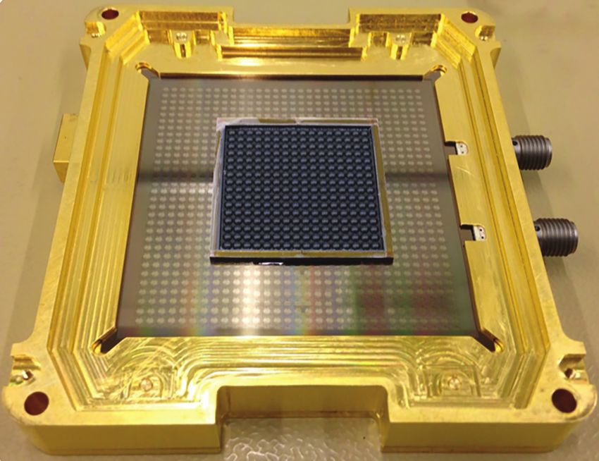
frequencies ((ωteff)2Figure 14: The SOFIA HAWC instrument
uses three 1280-pixel Backshort-Un-
der-Grid TES bolometer arrays developed
at GSFC (Staguhn et al., 2016). The inset
(right) shows HAWC+ polarimetry data
obtained on the Orion molecular cloud.
OriginsFT14
TES-C SiN Legs
350 μm x 0.5 μm x 0.25 μm
TES-A
Thermometer:
470 nm TiAu 16/65 nm
TES-B 50 μm x 50 μm
SiN Island
220 μm x 280 μm x
TES-C 0.25 μm
Free space Absorber:
Ta 8 nm, 200 μm x 200 μm
SED 15.0kV WD30.3mm Std.-P.C.26.9 HighVac. x43 500μm 7.0kV WD32.9mm Std.-P.C.64.4 HighVac. x120 100μm
0213 Jun 18 2015 0245 Jun 08 2015
OriginsFT15
Figure 15: Left: Test array of TES bolometers produced as part of the detector development program for the SRON-led SAFARI/SPICA in-
strument. Right: Close-up of a single pixel showing the silicon nitride thermal suspension, 8 nm tantalum film used as the optical absorber,
and 50 x 50 μm2 TiAu TES.
3.1.3 Theoretical Predictions for Current TES Technologies
Thermal isolation of TES bolometers is generally achieved by increasing the lengths of the beams
suspending the bolometer membrane. The state-of-the-art performance of the SRON TES pixel in
Figure 15 is a product of this approach. As shown in Figure 16, scaling the performance of an SRON-
like TES pixel to a lower bath and critical temperature suggests a path exists for meeting Origins/OSS
requirements. The models in Figure 16 also indicate that achieving increased thermal isolation of a
bolometer can significantly relax the requirements on the cryogenic system.
Below 100 mK, the phonon thermal wavelength exceeds 1 µm in silicon nitride (and single-crystal
silicon) beams. Thus, sub-micron features etched in a dielectric beam can serve to reduce the phonon
thermal conduction with a coherent phonon filter structure. The natural outcome of a phononic
structure is compactness, which is extremely desirable for achieving a high pixel filling-fraction in a
photon-starved instrument. An additional advantage of a phononic filter is the reduced sensitivity of
the conductance to variations in surface conditions (e.g., roughness). These properties enable a viable
path for producing uniform ultra-low-noise TES bolometers for Origins. As currently studied at GSFC
(PI Karwan Rostem), using a device suspended with legs that have phononic filters, a TES critical tem-
perature of 90 mK would be sufficient to meet the required OSS detector sensitivities.
From First Light to Life Vol 2-13The design and fabrication of phononic filter Tbath = 30 mK Tbath = 50 mK
isolation beams is currently implemented through 10–18
an APRA program (Rostem et al.), and described
in detail by Rostem et al., 2016, Bartlett et al.,
2019, and Olsson et al. (2015). This small effort
has led to a greatly improved understanding of 10–19
phonon transport at low temperatures and a leap
NEP (W/rtHz)
in phononic filter design and fabrication. As shown
in Figure 16, the NEP requirement for OSS can be
achieved with a phononic-isolated TES bolometer 10–20
at ~90 mK with a 50 mK bath temperature. The
150 x 100 nm2 (ballistic)
test pixel structure fabrication described in Olsson 500 x 200 nm2 (SRON-like)
et al. (2015) suggests scalability to 104 pixel arrays 150 x 100 nm2 with Phononic Filter
FIP Sensitivity
is possible and well matched to standard techniques 10–21
OSS Sensitivity
employed in electron-beam lithography. 0.05 0.1 0.15 0.07 0.1 0.15
TES Temperature (K) TES Temperature (K)
3.1.4 TES Challenges OriginsFT16
Figure 16: Sensitivity (NEP) plots for TES bolometers for various
To construct TES detectors that enable FIP and thermal isolation structures. At a bath temperature of 35 mK, a SRON
OSS performance requires designing and fabricat- type detector with TC of 55 mK provides a viable path for achiev-
ing detectors that obtain high sensitivity and high ing OSS sensitivity by reducing the bath temperature, which can be
pixel count simultaneously with high yield and done with current ADR technology (Section 2.2).
uniformity across the wavelength range of inter-
est. Fortunately, the sensitivity and format are separable problems, and in the last few years, solutions
have been demonstrated in the laboratory. Four steps to making these new detectors are:
1. Design and fabricate a single pixel at the sensitivity needed for FIP.
2. Design and fabricate a single pixel at the sensitivity needed for OSS.
3. Design and fabricate an array 1/3 the size needed for FIP with sensitivity required by FIP.
4. Design and fabricate an array 1/3 the size needed for OSS with sensitivity required by OSS.
3.1.5 TES Development Plan
Superconducting transition-edge-sensed (TES) bolometers are high heritage and have demonstrated
NEPs as low as 1×10⁻¹⁹ W Hz−1/2 at JPL and SRON. Attaining lower NEPs is possible in two ways: ei-
ther base temperatures must be reduced from the canonical 50 mK (a reduction to 35 mK is discussed
in Section 3.1.3) and/or the leg isolation needs to be improved, for example, with phonon-choke
micro-fabricated structures studied in an APRA program at GSFC (Rostem et al.). A principal disad-
vantage of TES systems, particularly for the formats required for OSS, is the complexity of focal plane
assembly for TES systems, in particular hybridization with superconducting quantum interference
devices (SQUIDs), typically one per detector. An ongoing SAT project (Staguhn et al.) is aimed at
simplifying this process. A key TES technology development is to demonstrate this hybridization at
the scale needed for Origins. Section 3.2 describes the readout electronics technology development
required that is scalable to large array sizes for TES.
To push the TES bolometers to the much-lower Origins sensitivities, and to larger array sizes, re-
quires a dedicated program between 2021 and 2025:
1. Task 1 (Year 2021): Develop extremely dark test environments for the FIR detectors. This task
requires very thorough test cryostat design. All electrical signal lines going into the cryostat must
be RF filtered to prevent miniscule amounts (less than one zepto-Watt) of electromagnetic power
from being transmitted to the test packages. Vibrational energy also must be kept away from the
From First Light to Life Vol 2-14detectors, so sophisticated vibration insulation (e.g., stiffness-controlled suspensions, eddy-current
dampers) is mandatory. The team will avoid introducing thermal radiation from any surface by
keeping the temperatures of all structures in the detector FOV below 2 K and, based on a surface’s
position and temperature, by using extremely black surfaces in combination with highly reflective
ones. Extremely low dissipation cryogenic readout systems, with as many dissipationless compo-
nents as possible, in well-shielded electronics boxes are also required. Multi-stage magnetic field
shielding elements are also essential.
2. Task 2 (Year 2021): Design and fabricate a single TES pixel that meets the FIP NEP requirement,8, 2-GHz baseband
input signals
HEMT Amplifiers x4
8x8 RFSoC-Based
RF Baseband
Conversion Card Detector Readout
TES Array Signal Processor Card
RF Up/Down 8, 4 GSPS ADC input channels
Conversion & Filtering SpaceWire I/F
6.4 GSPS DAC output channels to C&DH
Attenuators x4
8, 3-GHz bandwidth
baseband output signals
Flux-Ramp Modulation Signals
Detector Bias Signals
OriginsF155
Figure 18: Block diagram showing the flow of signals from the detectors on e.g. FIP to the warm electronics on Origins.
spaced evenly in frequency to occupy the full bandwidth. The resulting RF signal occupies 4 to 8 GHz
in the microwave spectrum, commensurate with the bandwidth of a single HEMT cryogenic amplifi-
er. Current research has demonstrated up to 2000 microwave resonators occupying 4 GHz bandwidth
can be effectively read out by warm electronics that are akin to a communications system or radar re-
ceiver. Readout involves down-converting the 4 GHz FDM signal, digitizing it, and applying a digital
filterbank to isolate the TES signals at each resonant frequency (Figure 18). The TES signals are then
acquired, coherently averaged, and passed to a C&DH system where telemetry operations packetize
and transmit the resulting data. Using this methodology, the TES array only requires a small set (~10
or fewer) of DC bias current signals for the entire array and a slow (~100 Hz) common flux-ramp
modulation signal to linearize the detector array.
A microwave multiplexed TES readout where each TES has its own microwave resonator is the least
bandwidth-efficient packing approach, but the one with the highest TRL; it has been demonstrated
in the lab (https://www.xilinx.com/products/silicon-devices/soc/rfsoc.html) and has the lowest complexity.
Since ~2000 resonators fit within a 4 GHz processing bandwidth, and ~10,000 resonators need to be
read, a total of five RF signals need to be connected to corresponding HEMT amplifiers and transmit-
ted downstream for signal processing.
The two detector arrays of the upscoped FIP design are combined into a set of two 4 GHz band-
width RF signals. These signals are down-converted and split into four 2 GHz bandwidth signals.
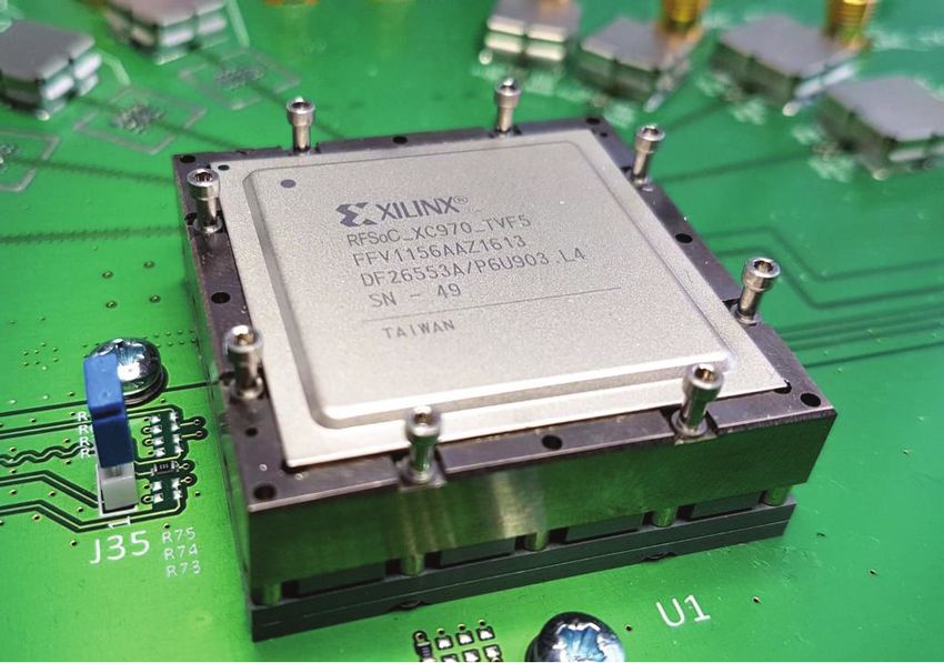
A new enabling technology developed by Xilinx Inc. is the RF System-on-Chip (RFSoC). This key
technology combines eight 4 GSPS RF-Sampling ADCs, eight 6.4 GSPS RF-Sampling DACs, a quad-
core ARM-A9 microprocessor, and Xilinx Ultrascale+ digital logic into a digital chip. At 200 MHz,
this chip utilized ~30 W. The FIP RF signals are all sampled and processed simultaneously by a single
RFSoC. The detector feedback and row current signals used to control the TES arrays can also be
controlled by the RFSoC and a combination of digital electronics on the same board. In 2017, Xilinx
demonstrated this technology in a related environment. Bringing this technology from TRL 3 to TRL
5 will require additional investment.
3.2.2 Hybridized Time-Frequency Division Multiplexing with Microwave Multiplexing
In this approach, an entire array of TES elements is coupled to a single microwave squid multiplexer
rather than to just a single TES element (Figure 19). In theory, a 32-TES array using Time-Frequency
Division Multiplexing (TDM) can be coupled to a single resonator circuit that is read out in a man-
From First Light to Life Vol 2-16You can also read