THE DIASONOGRAPH STORY - Tony Whittingham - IOMP, MEDICAL PHYSICS ...
←
→
Page content transcription
If your browser does not render page correctly, please read the page content below
MEDICAL PHYSICS INTERNATIONAL Journal, Special Issue, History of Medical Physics 6, 2021

                               THE DIASONOGRAPH STORY
                                             Tony Whittingham
     Formerly Regional Medical Physics Department, Newcastle upon Tyne NHS Trust, UK and Newcastle University

                                               I. BACKGROUND.

   Up to the time when Ian Donald started to experiment with ultrasound in Glasgow there had already been
many significant developments in diagnostic applications of ultrasound around the world. A number of
researchers had managed to acquire industrial flaw detectors and publish the results of their A-mode
investigations of tissues. In 1949, R P McLaughlin and G N Guastavino at the Argentinian laboratory of the
American electronics company RCA, published a paper describing their own pulse echo instrument for detecting
foreign objects in tissue, including the example of a stone embedded in an excised kidney [1]. In the same year,
George Ludwig, a medical officer, and Francis Struthers, a physicist, both at the Naval Medical Research
Institute in Bethseda, Maryland, measured the acoustic properties of a range of tissues and demonstrated
gallstones implanted in dogs [2]. Also in 1949, John Wild, an English surgeon working at the University of
Minnesota in the USA, measured changes in bowel wall thickness [3]. In 1953, cardiologist Inge Edler and
physicist Hellmuth Hertz, in Lund, Sweden, experimented with an industrial flaw detector, borrowed from a
shipyard, and interpreted moving echoes from within the heart. By 1954, they had invented the M-mode
technique for recording and measuring echo movements and had published M-mode echo recordings of the
hearts of living patients, establishing what was to become the diagnostic technique of echocardiography [4]. In
1956, G Mundt and W Hughes described their use of a flaw detector for A-mode examination of in vitro
enucleated eyes and patients with intraocular tumours [5].

                             Fig. 1 The Kelvin and Hughes Mark IIb Flaw Detector.
   In the late 1940s, Valentine Mayneord, Professor of Physics as Applied to Medicine, at the Royal Cancer
(later Marsden) Hospital in London, picked up on Wild’s early work and started to investigate the application of
ultrasound A-scans to the brain, a very challenging organ to study with ultrasound due to attenuation, reflection

                                                       565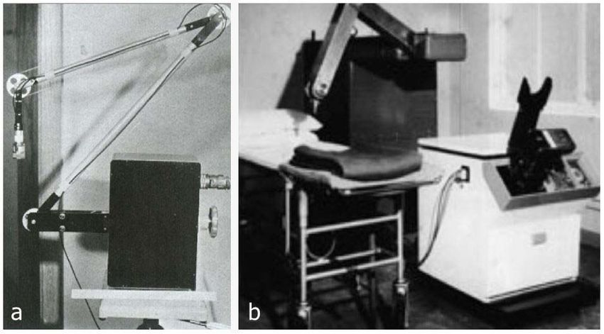
MEDICAL PHYSICS INTERNATIONAL Journal, Special Issue, History of Medical Physics 6, 2021

and refraction by the skull. R C Turner, an electronic engineer in Mayneord’s department, using a Kelvin and
Hughes Mark IIb industrial flaw detector (Figure 1), was sometimes able to show that an echo from the midline
of the brain could be displaced towards or away from the probe if there was a space occupying lesion in either
hemisphere [6]. Turner demonstrated his findings to Swedish neurosurgeon Lars Leksell during a visit by the
latter to Mayneord’s department [7][8]. Later, in 1950, Leksell borrowed a similar Kelvin and Hughes Mk IIb
flaw detector but failed to improve much on Turner’s patchy success [9]. However, when he replaced the Kelvin
and Hughes instrument with the Siemens flaw detector that his cardiologist colleague Elder had used, he found

                      Fig. 2 Water bath compound scanning system of Howry et al., c 1957. This water-
                      bath was based on the gun turret of a WW2 B-29 bomber. Photo courtesy of AIUM.
he could demonstrate shifts of the midline echo more clearly. His results, published in 1955 [10], led to the
establishment of echoencephalography as a valuable diagnostic tool.
   Cross-sectional (B-mode) images of human subjects were first achieved by two groups in the USA. One
group was led by radiologist Douglass Howry, in Denver, USA, while the other consisted of Wild, mentioned
above, and his electronic engineer colleague, John Reid, in Minneapolis. Between 1949 and 1954, Howry’s
group constructed a number of ‘Somascope’ instruments which required the subject to sit in a water bath, across
or around which an ultrasound transducer was automatically scanned [11]. In the later versions, the direction of
the ultrasound beam was changed between passes of the transducer, producing ‘spatially compounded’ images in

               Fig. 3 John Wild (left) demonstrating the hand-held 15 MHz contact scanner developed by himself
               and John Reid (right) c 1953. From the front cover of Electronics magazine, March 1955.

                                                             566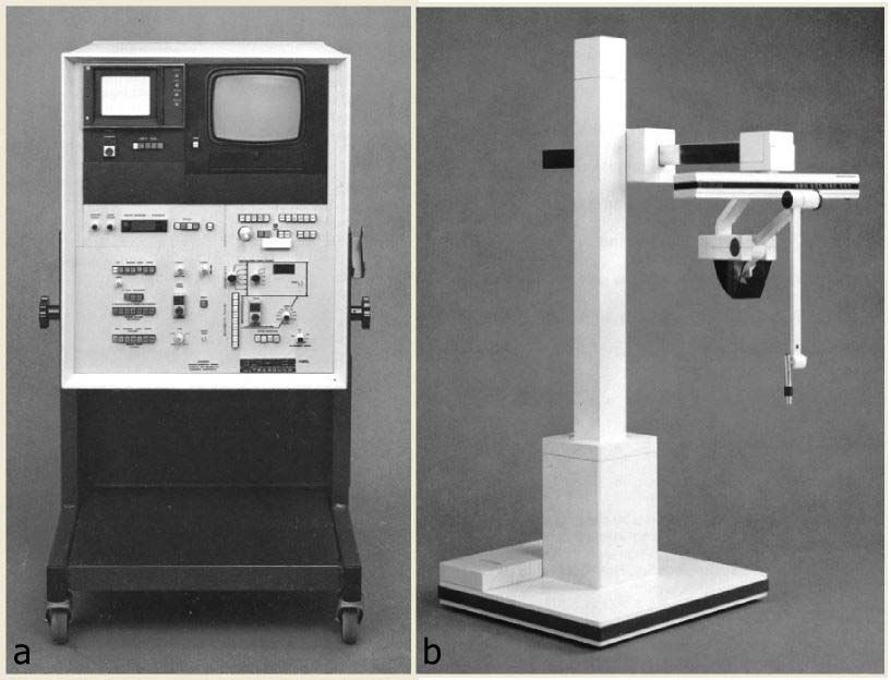
MEDICAL PHYSICS INTERNATIONAL Journal, Special Issue, History of Medical Physics 6, 2021

which each anatomical target was insonated from several directions and the echoes summed [12] (Figure 2). This
resulted in improved spatial resolution and better delineation of specularly reflecting tissue interfaces. The need
for immersion was avoided by Wild and Reid who, in 1953, built the world’s first hand-held ultrasound contact
scanner, which they used successfully to produce grey-scale images of breast tumours [13]. This ‘Two-
dimensional Echoscope’, as Wild called it, had a small water-filled chamber with a flexible rubber membrane
forming its base, mounted beneath it (Figure 3). A 15 MHz transducer was driven back and forth within this
chamber by an electric motor and worm screw drive.

                                                     II. IAN DONALD.

   Before his move to Glasgow, Ian Donald (Figure 4) held the post of Reader at the Institute of Obstetrics and
Gynaecology at the Royal Postgraduate Medical School, Hammersmith Hospital, London. During his previous
clinical career, he had demonstrated a talent and enthusiasm for innovation by developing improved mechanical
devices for the diagnosis and treatment of respiratory problems in neonates. Donald had read Wild’s 1951 paper
in the Lancet [14] and was able to speak with him directly when Wild visited the Royal Postgraduate Medical
School during an extended visit to London to deliver the University Lecture in Medicine. Wild showed Donald
slides of some of his A-mode and cross-sectional (B-scan) ultrasound images. They also discussed [15] the
possibility of using ultrasound to image the gravid uterus, Wild indicating that, in view of its cystic nature, a
lower frequency would be more appropriate than the 15 MHz that he had been using. Wild had also visited
Mayneord to hear of his work with the brain, so he knew of the Kelvin and Hughes flaw detector and suggested
something similar might be suitable if Donald wanted to take further the possibility of obstetric applications.
Donald was unable to attend Wild’s lecture himself, but Mayneord, who Donald knew through his interest in his
work, gave him an account of it [15]. Apart from describing his ultrasound breast imaging work in his lecture,
Wild had included a discussion of how ultrasound might be applied to the lower abdomen. He had also
commented on the safety of using ultrasound on live subjects, advising that a positive but cautious approach to
safety was justified, given the absence of evidence of tissue damage at the ultrasound intensities used.

                             Fig. 4 Ian Donald. Photo courtesy of the BMUS Historical Collection.
                             Photograph held in NHS Greater Glasgow and Clyde Archives.

    In September 1954, Ian Donald took up his post as the Regius Professor in Obstetrics and Gynaecology at the
University of Glasgow. For a while he collaborated with John Lenihan, of the Western Hospital Board’s
Regional Department of Medical Physics, and in particular with physicist and engineer Ronald Greer,
continuing his efforts to develop novel respiratory equipment and to investigate the respiratory changes during
the first breath of the newborn. However, it proved difficult to make further substantial progress into the problem
of neonatal respiratory distress [16] and Donald realized a change to a new project might be timely. He was
aware that differentiation between ovarian cysts and fibroids was an important clinical problem, with potentially
life-threatening consequences for the patient, so he decided to experiment with ultrasound to see if it could help.

                                                            567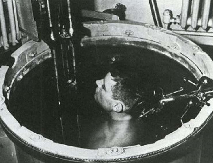
MEDICAL PHYSICS INTERNATIONAL Journal, Special Issue, History of Medical Physics 6, 2021

    One of the first things he did was to borrow a powerful ultrasound generator “from a friend of a friend in a
scientific instrument factory near Paisley” [17] and noted that red cell destruction depended on exposure time.
He concluded that the degree of cell damage was directly proportional to the heat generated [18] and considered
that the use of ultrasound would be safe as long as no significant heating occurred. In the spring of 1955,
through an introduction by a grateful patient, he was invited to the Renfrew factory of the boiler making
company, Babcock and Wilcox, where he was given a demonstration of a flaw detector, made by Kelvin Hughes
Ltd [18]. Although Donald was probably not aware of the significance, this was their latest, much improved,
Mark IV model with a single hand-held probe containing two piezoelectric transducers, one for pulse
transmission and one for echo reception; these were arranged in a shallow ‘V’ configuration so the crossover
region of their beams extended several centimetres from the probe [19]. He noticed that the technicians used
their thumbs several times a day to check that the instrument was working satisfactorily, reinforcing his opinion
that there was no significant hazard from ultrasound exposure. A technician also demonstrated that the echo from
the bone could be identified and that its position along the time-base trace on the A-scan display shifted back and
forth as the probe was pressed in and out against the thumb.
    In July 1955, Donald arranged a second visit to Babcock and Wilcox, this time using the flaw detector himself
to examine uterine fibroids and a large ovarian cyst, freshly removed from patients that morning. Donald
reported that the results from the flaw detector were as he had expected from his reading of the published
literature [18]. This gave him encouragement, although Fleming and Nicholson have since argued that his
interpretation of the echo patterns may have involved a degree of wishful thinking and that he may have been
lucky to find the controls already set appropriately [20]. Shortly afterwards, Donald visited Prof. Mayneord at
the Marsden Hospital. He found the team somewhat discouraged by the difficulties they had encountered, to the
extent that they had decided to replace their Kelvin and Hughes flaw detector with an A-scan machine they were
building themselves. They were, therefore, in a position to offer their Kelvin and Hughes Mk IIb flaw detector as
a loan to Donald [21].
    On his return to the Western Infirmary, Donald enlisted the help of Greer and, together, they tried to
reproduce the results that Donald had achieved during his second visit to Babcock and Wilcox and to move on to
investigating the intact abdomen. Unfortunately, they had little success, largely because the Mk IIb flaw detector
they were using was inferior to the later, Mk IV, model that Donald had used at Babcock and Wilcox. Its
performance had been further compromised by a modification made by Turner, while working on the midline
shift project in Mayneord’s Department. In its original form, the Mk IIb machine had separate transmit and
receive probes in order to prevent the large excitation voltage applied to the transmit transducer from temporarily
overloading and paralyzing the receiving amplifier. Unfortunately, it proved extremely difficult to hold these two
probes close together on the curved skull of the patient. By replacing the two probes with a single probe for both
transmission and reception, Turner had solved this ergonomic problem but in so doing he had reintroduced the
paralysis problem, making it impossible to detect echoes from within 8 cm of the probe face. Donald and Greer
tried introducing water offsets between the probe and the patient in order to overcome this serious limitation,
both in the form of open-ended tubes with a rubber membrane at the patient end [22] and in the form of water-
filled sealed condoms[18], but these did not prove to be suitable as a long term solution for clinical use. Despite
further help when obstetrician John MacVicar (seen on the right in Figure 12), then a registrar in the Department
of Midwifery, joined the team sometime in 1956, they still could not obtain consistent echo patterns from within
the abdomen, nor reliably interpret them.

                                III. TOM BROWN AND KELVIN AND HUGHES LTD.

   This rather unsatisfactory state of affairs continued until Tom Brown (Figure 5), a twenty-three-year-old
engineer with Kelvin and Hughes Ltd, at Hillington, Glasgow, heard that a professor was using one of the
company’s flaw detectors to examine patients. Brown had previously impressed his employers by his work in
helping to develop a semi-automatic flaw detecting system to the extent that they had sponsored him for a course
in applied physics at the Royal College for Science and Technology in Glasgow (now Strathclyde University).
Unfortunately, the mathematical content of the course had proven too challenging for Brown and he had to drop
out after one year [23]. As he said himself: “I spent too much time playing snooker and generally enjoying the
student lifestyle” [24}. His employers took him back, but he was now looking for a way to redeem himself in
their eyes. The idea of applying ultrasound to medical diagnosis appealed to him so, one evening in late 1956, he
telephoned Donald; his boldness was rewarded by an invitation to visit Donald at the Western Infirmary. Despite
what he called a “rather comical demonstration with the water stand-off and all the rest of it” [24], Brown could
see there were echoes coming back from within the patient’s body, so he called his boss, Alex Rankin, Head of

                                                       568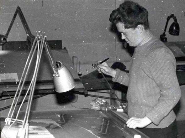
MEDICAL PHYSICS INTERNATIONAL Journal, Special Issue, History of Medical Physics 6, 2021

Applications Engineering, to tell him of the potential new application. Rankin was already well disposed towards
medical projects involving ultrasound, having provided support to Leksell in Sweden. He immediately arranged
for a brand-new Mk IV flaw detector to be delivered to Donald [23].

                                Fig. 5 Tom Brown, pictured around the time he built the bed-table
                                scanner. Photo courtesy of the BMUS Historical Collection.

    The new instrument made all the difference to the success of Donald and MacVicar’s A-scanning efforts
(Figure 6). Probes were provided at ⅝ MHz, 1.25 MHz, 2.5 MHz and 5 MHz, but they soon established that a
frequency of 2.5 MHz gave the best compromise between penetration and spatial resolution for obstetric
patients. In addition, Brown’s company was able to provide them with a Cossor oscilloscope camera to record
the A-scans on 35 mm film [23]. Hitherto, their only means of recording A-scan traces had been by sketching
them. Donald was very pleased, as the ability to produce accurate photographic records of the traces was
important for publication of any noteworthy results.

                   Fig. 6   A-scan of a simple ovarian cyst, c 1956. Photo courtesy of Tansey and Christie [24].

   Donald also appreciated the involvement of an engineer with substantial practical experience of the most
recent developments in industrial ultrasound technology. As a result, Brown was welcomed into the fold whilst
Greer’s involvement came to an end [23]. At first, Brown’s involvement was purely informal, with him going to
the Western Infirmary in the evenings, after his day’s work at Kevin and Hughes at Hillington. There, he would
perform any necessary maintenance and help MacVicar develop and analyse film from the day’s clinical work.
In order to learn how to interpret the echo traces, they would experiment by applying the probe to their own

                                                                569
MEDICAL PHYSICS INTERNATIONAL Journal, Special Issue, History of Medical Physics 6, 2021

bodies, as well as to rubber membrane acoustic windows built into the walls of water tanks containing surgically
removed cysts and tumours [25]. Donald, however, had little time for such in-vitro experimentation, preferring
that the probe be applied directly to real patients [26].
   Donald was happy to arrange an abundant supply of patients and he drove the project forward with
characteristic energy. By mid-1957, with Brown’s assistance, he and MacVicar were providing a clinically
useful service to gynaecological patients and starting to look at obstetric patients. Through their hard-won and
growing expertise in interpreting the A-scans, they had largely solved the original challenge of differentiating
cysts from solid tumours and they could even differentiate between different types of cysts. There had been
occasional mistakes, as when a highly vascular fibroid had been mistaken for a cyst [27], but this all contributed
to the learning process; consequently, the initial scepticism amongst Donald’s clinical colleagues at the Western
Infirmary was disappearing. The much-quoted turning point in the acceptance of the technique was when a
swollen abdomen, thought by the Regius Professor of Medicine to be due to ascites, secondary to inoperable and
terminal cancer, was being ultrasonically examined by Donald. Looking over Donald’s shoulder, MacVicar,
commented that the trace looked like that of an ovarian cyst. Although MacVicar was rewarded by an unseen
kick from Donald for contradicting the Professor of Medicine’s diagnosis, Donald accepted that an ovarian cyst
was a possibility and arranged for a laparotomy, which confirmed that the mass was indeed a very large ovarian
cyst. This was duly removed and, instead of being allowed to die, the patient made a full recovery [24][28].

  A. The Bed-table Scanner
   Notwithstanding Donald and MacVicar’s satisfaction and excitement with the clinical value of A-scanning
using the Mk IV flaw detector, Brown was convinced that a display that showed the positions of each reflecting
interface was needed to fully exploit the potential of the ultrasound pulse-echo technique. He felt that, ideally,
since the human body was three dimensional there should be a 3D representation of the echo sources. This was
to remain his ambition throughout his life [23] [24] but, for now, he accepted that an image of a 2D cross-
sectional slice of the patient would have to suffice. According to Brown [23], Donald was initially less
enthusiastic about what 2D imaging could offer. This was despite the interest Donald had shown in radar and
sonar during his wartime military service and the 2D ultrasound images he had seen in the publications of
Howry’s team in Denver and of Wild and Reid in Minnesota. He had even attempted, unsuccessfully, to build a
2D ultrasound system himself in his early days in Glasgow, although very little is known about it [22]. He felt
the detailed echo information from within organs and other body masses that he was now obtaining had more
diagnostic value than knowing the position of a reflecting interface [29]. For whatever reason, Donald chose not
to show Howry’s or Wild’s cross-sectional images to Brown. Years later, Brown said “I think that had we been
aware of what Howry was doing and had set out our stall to improve on Howry’s work, we would have been
stuck with immersion scanning” [24]. Having seen the trouble caused by attempts to use water offsets when he
first visited Donald, Brown was very keen to avoid using water, either for partial immersion of, or acoustic
coupling to, the patient in a hospital environment. He also wanted a system that could be used at the patient’s
bedside, as was possible with the A-scan unit. It is a matter of conjecture what the outcome would have been if
Brown had known of Wild and Reid’s relatively compact hand-held contact scanning system: perhaps he might
have been inspired to try to build a low frequency development of it.
   From his knowledge of the radar work undertaken by Kelvin and Hughes, Brown was familiar with “True
Motion” radar displays, in which the screen acted as a fixed map on which the position of the transmitting
aircraft or ship, as well as the positions of echo-returning targets, were updated after every sweep of the beam.
He considered applying the technology of this technique to the medical situation [23] but radar experts at Kelvin
and Hughes quickly made him realize this approach would be unnecessarily complex. Whereas, in the case of
radar, the position of the transmitting ship or aeroplane had to be calculated from the echo data returning from
land-based targets, in the medical situation the position of the probe could be measured directly by mounting it
on a support arm or mechanism from a fixed point. From the known transducer position, the positions of echo-
producing targets could be plotted on the screen of a cathode ray tube (CRT) using the standard ‘plan position
indicator (PPI)’ method of radar displays. Brown’s proposal was supported by his managers at Kelvin and
Hughes, including the company’s Chief Scientist, Bill Halliday. However, the crucial move was made by
Donald, who was keen to put Brown’s input on a formal footing [23]. Donald arranged to meet William Slater,
Deputy Managing Director of Kelvin and Hughes, impressing him with his account of the clinical value of the
project and its potential. The result was that half a day per week of Brown’s time was allocated to working with
Donald, along with a budget of £500 to make the first machine. Brown later said this figure turned out to be very
elastic [23].

                                                       570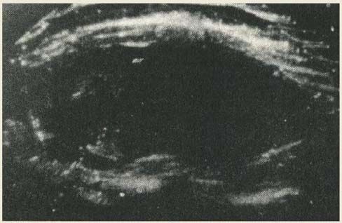
MEDICAL PHYSICS INTERNATIONAL Journal, Special Issue, History of Medical Physics 6, 2021

   During 1957, Brown designed and built his prototype system [30] [23] in the research department of the
Kelvin and Hughes factory at Hillington. He felt that a system in which the probe was in direct contact with the
patient was required, in the same way that the probe of a flaw detector was applied directly to the test piece in an
industrial setting. Mindful of the convenience of being able to use the system on a patient in a hospital ward, he
chose to build his prototype around a wheeled bed table. A photograph of the resulting ‘Bed-table scanner’ being
used by MacVicar to scan Brown’s abdomen is shown in Figure 7.

                         Fig. 7 Tom Brown’s bed-table scanner, c 1957. Note the restricted room for the operator’s
                         forearm and hand (seen lower left). Photo courtesy of the BMUS Historical Collection

   The user could move the transducer by hand anywhere within a fixed vertical transverse ‘scan plane’, keeping
the transducer face lightly pressed against the patient’s skin, which was kept lubricated with vegetable oil. The
scan plane was defined by the position of a wheeled carriage that could be moved transversely on rails across the
bed table. At any position within this plane, the transducer could be rotated or rocked through a large range of
angles, thus giving the benefit of compound scanning, mentioned previously in connection with Howry’s system.
The scan plane could be moved longitudinally by simply moving the bed table above and along the bed on which
the patient was lying. Three displays were provided: an A-mode display, at that time still considered essential by
Donald and MacVicar: a B-mode display on a long persistence CRT screen, which the user could monitor as he
moved the probe around in an exploratory fashion; a second B-mode display, this time on a short persistence
CRT fitted with a camera for when the user had found a particular cross-sectional view that he wished to record.
Figure 8 shows two of these displays: on the left is a Mark IV flaw detector used to display A-scans and, on the
right, is a CRT with a Thompson-Polaroid Land camera attached for recording B-scans.

       Fig. 8   Displays and camera from the bed-table scanner. Photo courtesy of the BMUS Historical Collection.

                                                                 571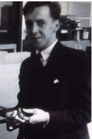
MEDICAL PHYSICS INTERNATIONAL Journal, Special Issue, History of Medical Physics 6, 2021

   The hand-guided probe could be rotated about a horizontal spindle whose X and Y coordinates were measured
by means of a system of wires and pulleys connected to the shafts of wire-wound X and Y linear potentiometers.
The angle of the probe, and hence the ultrasound beam, to the Y axis of the measuring frame was measured by
linking the rotation of the probe to the shaft of a sine-cosine potentiometer (Figure 9). By applying stable
positive and negative voltages of equal magnitude (+v and -v) respectively to the diametrically opposite sides of
the potentiometer’s circular track, the resistance per unit length of which varied sinusoidally, the two wipers,
arranged 90° apart on the potentiometer shaft, picked off voltages of v cosѲ and v sinѲ respectively, where Ѳ
was the angle of the probe to the Y axis of the measuring frame. Each of these voltages was applied to its own
integrator circuit, producing two voltage ramps with slopes proportional to v cosѲ and v sinѲ respectively. A
voltage proportional to the Y coordinate of the probe spindle was added to the v cosѲ ramp and a voltage
proportional to the X coordinate of the spindle was added to the v sinѲ ramp. This provided vertical and
horizontal voltage drives, respectively, for the time-base on the CRT used for the display. When the time-base
had swept across the screen to reach a point corresponding to the probe face (with a correction to allow for the
perspex block in front of the transducer) the transmitter was triggered. From this moment on, the position and
orientation of the time-base trace on the CRT screen matched the position and orientation of the transmit-receive
ultrasound beam within the scan plane. The speed at which the time-base spot of light was swept across the
screen depended on the magnification required.
   For unity magnification, for example, echoes from two targets a certain distance apart, both lying on the axis

              Fig. 9 Left: Measurement of probe angle Θ relative to the Y axis of the scan plane. Right: The ‘cosine’
              wiper of the sine-cosine potentiometer is at the same angle as the principal axis of the probe.

of the beam, must be represented by echoes the same distance apart along the CRT time-base. In order to allow
for the two-way travel of the sound pulse in the body, this requires the spot of light to be swept along the time-
base trace at half the speed of sound in the body (approximately 1540 ms-1). For a magnification of one half, the
spot of light would have to be swept across the screen at one quarter of the speed of sound, and so on. This
arrangement was similar to the measuring system used later in the Diasonograph machines. A then popular
construction kit known as ‘Meccano’ was used to provide many of the smaller components, such as chains,
sprockets and pulley wheels, but some of the larger and more critical components were manufactured by
technicians in the model shop at the Hillington factory.
   The probe was that of the Mark IV flaw detector. It housed two rectangular, 10 x 7 mm, unfocussed, air-
backed barium titanate transducers, one for transmission and one for reception. They were mounted, side by side
with their shorter sides adjacent, on one of the flat faces of a one inch (25.4 mm) thick cylindrical Perspex block,
the opposite flat face being in contact with the patient [30]. As mentioned earlier, the use of separate transducers
for transmission and reception avoided the problem of paralysis encountered in the modified Mk II flaw detector
initially used by Donald. The transducer dimensions were chosen to give a compromise between beam width in
the near field and angular divergence in the far field. Another consequence of using two transducer elements
side by side was that the overlap of their beams increased with distance from the probe face, producing a two-
way sensitivity that increased progressively with depth. This provided a degree of compensation for the effect of
attenuation on echo strength from deeper targets and explained why swept gain (later often called TGC - time
gain compensation) was not considered a high priority. A resonant frequency of 2.5 MHz was chosen for the
transducers, corresponding to a transducer thickness of approximately 1 mm, as the earlier in-vitro experiments
made by Brown and MacVicar had indicated that this frequency would give an optimum compromise between
spatial resolution and penetration for use in the lower abdomen. The transmission pulse generator and receiver
were those of the Mark IV flaw detector [31]. The transmission transducer was shock excited by a pulse of
approximately 2 µs duration, generated by charging a 100 pF capacitor to about 1.4 kV through a high resistance

                                                                572
MEDICAL PHYSICS INTERNATIONAL Journal, Special Issue, History of Medical Physics 6, 2021

and then triggering a thyratron to discharge it though the primary winding of a pulse transformer, across the
secondary winding of which was connected the transducer in parallel with a 50 ohm damping resistor [30].
   The other electronic circuits and components were also largely those used in the Mark IV instrument. Brown
chose a pulse repetition frequency (PRF) of 50 Hz, partly because this was one of the standard PRFs of the Mark
IV and partly because it represented what he considered to be a prudent compromise between safety and
performance. A higher PRF would have allowed the probe to be scanned across the abdomen more quickly,
without increasing the gaps between lines of echoes on the display, but it would also have meant that the patient
would have received more ultrasound energy. On testing an early version of the apparatus by scanning a
grapefruit suspended on a wire in a water tank, Brown realized the signal processor stage, the output of which
was used to brightness modulate the time-base trace on a CRT, needed to be more sensitive. He described this
circuit as being “where art and science tended to co-exist” [23], but he nevertheless managed to achieve a very
acceptable dynamic range of the order of 60 dB.
   The increased receiver sensitivity allowed him to introduce another safety feature in the form of a switched
attenuator in the transmit voltage drive to the transducer. If the displayed echoes were too strong, the operator
could reduce their amplitude by means of the attenuator, leaving the receiver sensitivity (gain) at its high level.
He recommended that the operator should start with a high transmitter attenuation setting and, only if necessary,
reduce it to the level needed to achieve a useful image, thus helping to ensure that the patient received no more
ultrasound power or intensity than was necessary. Brown’s estimate of the maximum acoustic intensity that his
scanner was capable of producing in the patient was 1.5 mW cm-2 and the maximum acoustic power was
approximately 1.0 mW [30]. These values are tiny in comparison to the corresponding figures for obstetric
ultrasound scanners post-1990 [32] and were considerably less than those of either Howry [33] or Wild [34].

            Fig. 10   Example of a scan produced by the bed table scanner. It shows a uterus containing a fetus (left) and a
            fibroid (right). Reproduced from Figure 17 of Donald, MacVicar and Brown, The Lancet, 1958 [30].

   In late 1957, the machine was sufficiently developed to be put into use in the Western Infirmary, but Brown
admitted to some disappointment at the quality of the images [35]. Figure 10 shows the scan of a uterus,
obtained with the scanner, with barely recognizable echoes from an early stage fetus on the left and what was
thought to be a fibroid on the right [30]. Brown and MacVicar frequently scanned each other to discover the
limitations of the apparatus, how to get the best out of it, and which aspects of it required improvement. In
observing clinicians using the system on patients, Brown recognized that the scanning technique varied
considerably between operators and this had a large effect on image quality. Operator skill was not helped by the
poor ergonomics of the system, which, Brown later admitted, had not been given much consideration during the
design; in fact he described it as “ergonomically horrific”, but added “it was all done, after all, on a £500 budget”
[24]. For example, the user had to reach into the narrow space between the table and the patient (Figure 7) to
manipulate the probe whilst turning their head away to see the display screens. Brown was able to improve
results by making further modifications, including the updating of the amplifier with one from his company’s
new Mark V flaw detector which gave superior performance [31]. In order to overcome the restriction of being
able to scan only in transverse vertical planes he later replaced the bed-table with another over-bed, structure, in
the form of a wheeled steel framework. This allowed the operator to scan in planes perpendicular or parallel to
the longitudinal axis of the patient’s body, and in planes inclined to the vertical, as desired [36]. Another later
improvement was the replacement of the Cossor oscilloscope camera with a Thompson-Polaroid Land camera.
This allowed photographic records of scans to be viewed in the scan room within minutes, rather than having to

                                                                  573
MEDICAL PHYSICS INTERNATIONAL Journal, Special Issue, History of Medical Physics 6, 2021
wait for a full roll of film to be exposed and then waiting a further period of hours for it to taken away, processed
and returned. A potential disadvantage of Polaroid film was that it was less sensitive than conventional film.
Initially, this resulted in the loss of weaker echoes but, after carefully reading Polaroid’s technical literature,
Brown solved the problem by designing an illumination box in which the Polaroid film could be briefly pre-
exposed, increasing its sensitivity. These improvements all helped to foster marked and growing enthusiasm
from Donald for the B-mode technique. By the time of submitting their June 1958 publication ‘Investigation of
abdominal masses by pulsed ultrasound’ in The Lancet, Donald and MacVicar, with Brown’s technical input,
had used the bed-table scanner on 100 patients and had made 275 B-scan recordings [30].
In 1959, physicist Tom Duggan joined Donald’s team to work on ultrasound, his salary being paid from a
Scottish Hospital Endowment Research Trust grant that was intended to finance neonatal respiratory studies
[31]. Between 1961 and 1962 he developed a fetal ultrasonic cephalometer, by means of which two bright ‘pips’
could be superimposed on the A-mode trace on a Kelvin and Hughes flaw detector [37]. The instrument was
described as portable but it weighed 30 kg and had to be pushed about on a trolley [31]. The bright pips were
placed at the leading edges of the two echoes from opposite sides of the fetal skull at the level of the parietal
eminences. These echoes corresponded to the outside of the nearer side of the skull and the inside of the far side.
The time elapsed between the generation of these two pips was measured electronically and converted to an
estimate of the distance across the outside of the fetal head at this level, called the bi-parietal diameter (BPD).
This was achieved by multiplying by a factor of 0.080 cm μs-1, derived experimentally from measurements on
neonates and post-mortem fetuses [38]. Because this conversion factor relates a distance to a (two-way)
ultrasound time of flight, it is usually expressed by saying that the ‘caliper velocity’ is 1600 m s-1.
The ultrasonic estimate of the BPD became an important index for monitoring fetal gestation and
development, thanks to the efforts of John Willocks, a young doctor who had joined Donald’s team about the
same time as Duggan [37]. Later, Duggan joined Kelvin and Hughes, where he was involved with transducer
developments, before moving on to an academic post at the University of Strathclyde and thence to the Regional
Department of Medical Physics (now Clinical Physics and Bioengineering) at the West of Scotland Health
Board. There, he was closely involved with the introduction of ultrasound teaching and development laboratories
and with supervision of an ultrasound maintenance service [24].
Meanwhile, both Brown [23] and Donald [39] were frustrated by the variations between operators in probe
manipulation, artefact avoidance and other scanning skills, as these were limiting the success of their cross-
sectional imaging project. In Scotland in the mid-1950s, it was unthinkable that a young male engineer without
any medical qualifications could be allowed to scan patients himself, particularly on gynaecology and obstetrics
wards, so Brown was unable to demonstrate to others how to get more consistent results [23]. Mindful of his
prior success in helping to develop an automatic industrial flaw detecting system, it seemed to Brown that an
automatic clinical scanning system could provide the solution to the inconsistency problem as it would greatly
reduce the influence of the operator on the scanning procedure. Even if it proved too complex and costly to
consider as a prototype production machine, it would at least demonstrate the scanning action needed to produce
good images. Donald agreed and asked Kelvin and Hughes if they could provide an “apparatus which
automatically scanned the surface of the abdomen at a standard rate and rocking speed” [39].
B. The Automatic Scanner
Brown was aware that Kelvin and Hughes were investigating new probe designs in which the two rectangular
transducer elements of the Mark IV design were replaced by a single disc-shaped transducer element, offering a
much greater sensitivity than had been possible with the overlapping beam arrangement of the twin element
probe. Also, by this time in the late 1950s, new, more sensitive, piezoelectrics such as lead zirconate titanate
(PZT) were becoming available. Brown was keen to take advantage of these development as he was aware that
attenuation, and hence signal loss, was very much more of a problem in tissues than in the metal structures for
which flaw detecting technology had been developed. Not only would a higher sensitivity improve the dynamic
range of the detected echo signals, but it would have safety implications as it would mean that pulses of lower
energy could be transmitted. The large impedance mismatch between the transducer and the patient’s tissue
meant that the absorbing backing behind the transducer was more critical in suppressing ‘ringing’ than it was for
industrial applications. This backing was normally made from epoxy resin in which dense metal particles were
suspended but its performance could be degraded by gas bubbles trapped within it during the curing process.
Brown and Clive Ross, a colleague at Kelvin and Hughes whom Brown described as “very gifted” [23], used a
centrifuge to drive gas bubbles in the uncured epoxy resin away from the transducer as well as to give the
backing an inclined rear surface. In Brown’s own words, this allowed them to produce “some quite respectable
single transducer probes” [40]. Brown was by now aware of the work of Howry’s team, including their use of
574MEDICAL PHYSICS INTERNATIONAL Journal, Special Issue, History of Medical Physics 6, 2021
concave lenses to improve beam shape, so Ross experimented with different lens designs, finally settling on a
conical design, having decided it gave better results than lenses with the more conventional spherical curvature.
The new scanner was provided with a range of focused transducers, with the frequencies that were standard for
Kelvin and Hughes flaw detectors, namely 1.5 MHz, 2.5 MHz and 5.0 MHz. Brown later said that perhaps a
frequency of 3.5 MHz would have been optimum in terms of the compromise between spatial resolution and
penetration for gynaecological and obstetric applications but that this omission was not too serious in view of the
other limitations of the equipment at the time [40].
The electronics of the automatic machine were mostly identical to those of the updated bed-table scanner [40].
An important exception was that the receiver amplifier from the Mark IV flaw-detector could no longer be used
as, following the change to single transducer element probes, the transmission pulse produced too much receiver
paralysis. When developing the new Mark V flaw detector for Kelvin and Hughes, one of Brown’s colleagues,
John Woods, had found that the solution to this problem was to design a separate tuned RF amplifier for each
probe frequency. Consequently, separate plug-in RF amplifiers were provided for use with each probe of the
automatic scanner. A feature of the new amplifiers was that the amplifier gain could be made to increase with
time after transmission at a rate set by the operator. Without this feature, attenuation due to scattering and
absorption in tissue would mean that B-mode echoes produced by a single transducer element probe would
exhibit a general trend to diminish in brightness with depth. The new feature, known as ‘swept gain’, meant that
this attenuation could be compensated for in a controlled way by the operator. Previously, in the bed-table
scanner, using probes containing two transducer elements, a fixed degree of such compensation had been
provided by the increasing beam overlap with depth. Now, by judiciously adjusting the swept gain controls, the
general brightness of echoes could now be made more uniform at all depths. (Note that swept gain did not affect
the difference in brightness between a strong echo and a weak echo at similar depths).
Fig. 11.Drawing of the automatic scanner from Brown [23], showing all the
motorized movements. Courtesy of the BMUS Historical Collection
A diagram of the automatic scanner is shown in Figure 11. The finished machine, being used by Donald and
MacVicar; is shown in Figure 12; a clearer view of the silver ball probe is inset. The ingenious way in which the
probe was scanned and rocked automatically across the curved form of the patient is, perhaps, best described in
Brown’s own words [23]:
“The 'business end' of the automatic scanner consisted of a probe holder in a 'silver ball' - which
looked a little like the kind of soap dispenser once commonplace in public toilets. This was
mounted on a vertical, telescoping motor-driven column, such that it moved up and down to keep
575MEDICAL PHYSICS INTERNATIONAL Journal, Special Issue, History of Medical Physics 6, 2021
the probe face in contact with the patient's skin. It too was shiny chromium plate. A pressure
sensing switch ensured that it maintained contact with the skin, but with minimal pressure.
The silver ball rocked to-and-fro on an axle, driven by a system of cranks and connecting rods.
Slightly indelicate looking soft plastic "nipples" on either side of the ball touched the skin when
the probe axis had moved about 30 degrees to the perpendicular to it, and - almost as sensitive as
the real thing - caused the rotary motion to stop and then reverse its direction.
Each time the nipple touched the patient's skin, another set of relays and motors were activated
to inch the vertical column sideways. This, when combined with the compensating up/down
motion to keep the probe in contact with the skin, caused about a 15 mm tangential displacement
between successive "sweeps" of the rotating probe.
In this way the probe gradually 'walked' across the abdominal surface, rocking to-and-fro as it
went, carrying out what was actually quite a thorough, and highly consistent compound scan.
Of course, it was not quite as simple as that. To enable it to work properly on the steep flanks of
the often rotund ladies being examined, an automatic changeover mechanism operated at about the
45 degree point on either side of the vertical, so that the horizontal drive then controlled the
pressure, and the vertical drive did the 'inching'. The distance the machine 'inched' each time was
regulated by a profiled cam system, so that it remained constant, irrespective of the average angle
of the probe to the vertical. Nowadays it would all be done by microprocessor, but then it had to
depend on cams, switches and relays - and I guess it was the sort of thing which would have
delighted Heath Robinson.
There was a 'joystick' controller in a box on the end of a cable, by means of which the operator
could position the probe for the start of the scan, but when he had done so, his task was over. He
simply pressed the 'Auto' button, and the machine did the rest.
When it had finished, (about 90 seconds later on a big lady), it would switch itself off, and then
ring a bell to summon him back. It may seem unlikely, but such was the confidence which
developed in the machine, and the pressures of nicotine addition, that the bell became a necessity.”
Fig. 12 The automatic scanner being operated by Donald (left) and MacVicar (right). The ball
probe, viewed from another angle, is inset. Photo courtesy of the BMUS Historical Collection.
The large size of the somewhat intimidating box suspended above the patient was, in part, due to building-in
the capability to scan transverse, longitudinal and all intermediate planes, as well in planes tilted away from the
vertical. The tilt facility was little used, however, as users were not practised in the interpretation of the anatomy
in such oblique views. The other reason for the bulk and complexity of the system was the incorporation of an
optional facility for automatically stepping the scan plane in small increments perpendicular to itself in order to
576MEDICAL PHYSICS INTERNATIONAL Journal, Special Issue, History of Medical Physics 6, 2021
acquire a volume set of echo data. This reflected Brown’s enduring ambition to produce a scanner incorporating
both 3D echo acquisition and 3D display. In later years he was to work with Sonicaid Ltd, based in Bognor, UK,
to produce the radical “3D Multiplanar Scanner”, which produced three-dimensional stereoscopic virtual images
of body tissue but met with little commercial success [41]. Conscious of the disastrous consequences if the heavy
box ever were to fall onto a patient, Brown incorporated safety features such as ratchets and cams that would
prevent it falling more than a few millimetres should its support chain break. As might be expected with such a
complex mechanical system, malfunctions did sometimes occur. The most alarming being on one occasion while
scanning a “very stout” patient. The silver ball “started to dig in because the soft flabby fat stopped progress
across the abdomen and the probe oscillated on one spot, burrowing deeper into the six or eight inches of fat”
[24]. This was attributed to the patient, understandably, drawing away from the advancing ball, thereby inviting
it to advance further. A part may also have been played by congealed olive oil around the probe, inhibiting it
from moving up and activating the pressure sensing switch [42]. A white nylon ring was fitted later around the
ball, increasing its contact area and thus reducing the pressure experienced by the patient. Another problem was
electrical ‘snowstorm’ interference over the screen, caused by sparking across the contacts in the DC electric
motors. When this happened, somebody would be sent from Kelvin and Hughes to clean the contacts and to fit
suppressors and electrical shielding, as necessary.
While work on the automatic scanner was proceeding, a financial crisis had to be overcome. The £500 budget
Brown had been given by Kelvin and Hughes had already been spent many times over. In December 1959,
without any immediate prospect of commercial sales, and in view of Donald’s estimate that it could take a
further 15 years for diagnostic ultrasound to become routine, Brown was told by his manager at Kelvin and
Hughes that the company could not justify further financial backing for the project, although they had assured
Donald that they would complete the automatic scanner. Donald promptly sought the support of the University
of Glasgow and was immediately promised £750 towards the research project. Moreover, the University advised
him to approach the Scottish Hospitals Endowments Research Trust, which he did with Slater, and was rewarded
with a donation of £4,000. The Trust also advised him to apply to the National Research Development
Corporation (NRDC), an organization set up to assist British industry to compete internationally. This resulted in
the NRDC committing a total of £10,000 to Kelvin and Hughes towards the development of diagnostic
ultrasonic scanning over several years [43]. The crisis was over.
In July 1960, the automatic scanner was exhibited at the Third International Conference of Medical
Electronics, held at Olympia, London, but failed to attract any commercial interest. At this meeting, Donald and
Brown met Howry for the first time, initiating a long lasting, mutually supportive collaboration. Despite there
being no real hope of it being a marketable product, owing to its sheer complexity, Brown rightly described the
automatic scanner as “a lovely machine” and felt it had established a benchmark in image quality. As he had
hoped, it demonstrated effective scanning technique to trainee operators, helping to improve consistency of
scanning expertise. It was the means by which Donald and MacVicar developed their image interpretation skills
and understanding of the clinical role of diagnostic ultrasound, producing around 3,000 scans of reasonably
Fig. 13 Photographic record of the scan of an early pregnancy, obtained with the Automatic
Scanner. Cards showing patient and scan details were included in the same exposure using an
arrangement designed by Tom Brown. Photo courtesy of the BMUS Historical Collection.
consistent quality between 1959 and 1965 [24]. Figure 13 shows an example of an early pregnancy scan obtained
577MEDICAL PHYSICS INTERNATIONAL Journal, Special Issue, History of Medical Physics 6, 2021
using the automatic scanner, together with scan and patient information written on cards that were included in
the photographic record, a technique devised by Brown. It was replaced by the first manually operated
Diasonograph (see Section IV below), but it went on to do non-obstetric/gynaecological service in the hands of
radiologists Ellis Barnett and Pat Morley in the Glasgow Western Infirmary.
C. The ‘Sundén’ (Lund) machine.
Since 1953, Lund University had pioneered diagnostic applications of ultrasound, both to the brain by Leksell
[9], and to the heart by Edler and Hertz [4]. Professor Alf Sjövall, Head of Obstetrics and Gynaecology, had
taken an interest in this work and in May 1958 he had instructed a young doctor, Bertil Sundén, to use Leksell’s
equipment (a Krautkrämer flaw detector) to investigate the potential of ultrasound for his own discipline [44].
Donald visited Sjövall in June of that year to learn about the upcoming technique of laparoscopy and during his
visit he spoke about his own ultrasound work. On hearing of the achievements in Glasgow, Sjövall arranged for
Sundén to spend three weeks with Donald to learn what he could of the new ultrasound B-scan technique, which
at that time was based on the bed-table scanner. On his return, Sundén obtained a grant from the Swedish
Medical Council to buy a similar scanner for use in Lund. Much to the delight of Kelvin and Hughes, an order
was placed in 1959 for an agreed cost of £2,500. Although, by this time, the automatic scanner was well
advanced [23], Sundén requested a copy of the bed-table scanner he had used. This was never intended to be
anything but a prototype and so a replica was out of the question. However, there was no doubt that only a
machine with a hand-guided probe would be acceptable. Consequently, Brown and his managers at Kelvin and
Hughes turned away from the automatic scanning approach for this and any future orders and decided to design a
more refined manual contact scanner, with improved performance and ergonomics.
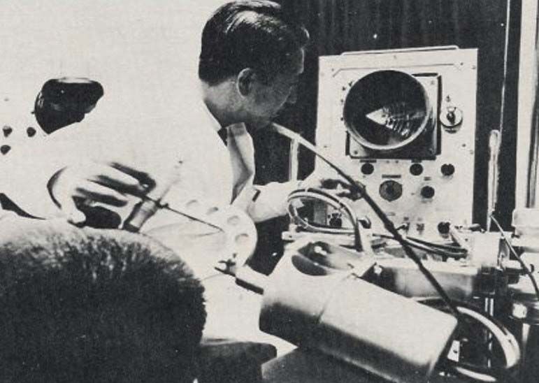
Fig. 14 Illustrating the principle of the system used to support and constrain the probe within the
scan plane and to obtain the X,Y and angle coordinates of the probe relative to the scan plane.
Through his recent friendship with Howry, Brown was aware of the possibility of using an articulated arm
(see section VIII B) to support the probe and measure its coordinates, but he continued to favour his original
Cartesian coordinate method because of its intrinsically more rigid and accurate, albeit heavy and bulky, nature
[23]. Figure 14 illustrates the general principle of the system of rails used to allow the probe free movement
within a firmly defined scan plane and to measure the probe’s X,Y coordinates and the angle of the probe to the
Y axis. A photograph of the actual mechanics of a later version of the scanner (NE4102) is shown later in Figure
23b, but those in the Sundén scanner were basically similar. One of the designers at Kelvin and Hughes
produced preliminary drawings of a machine to Brown’s rough specification, but the company had a background
in making equipment for industrial use and Brown felt the drawings did not suggest the kind of machine that
would be appropriate for a clinical environment. Thanks to a mutual contact in the form of his sister in law,
Brown met Dugald Cameron (Figure 15), a final year industrial design student at the Glasgow School of Art.
Brown recognised that Cameron’s talents and training could be just what was needed, so Cameron was
commissioned to produce drawings showing how the aesthetics and the ergonomics of the design could be
improved. Having first established that the machine should be planned around a single standing operator,
578MEDICAL PHYSICS INTERNATIONAL Journal, Special Issue, History of Medical Physics 6, 2021
Cameron set about making the design, as far as possible, both ergonomically convenient for the operator and
non-intimidating to the patient. An initial sketch by Cameron for the design is shown in Figure 16.
As may be seen in the photograph of the completed machine (Figure 17), an inverted-U outer frame was
Fig. 15 Dugald Cameron, in the east basement of the Mackintosh Building of the Glasgow
School of Art, using an air brush to produce presentation drawings for the Sundén scanner. Photo
reproduced by the kind permission of Dugald Cameron.
Fig. 16 Original sketch by Dugald Cameron of Kelvin and Hughes’ concept for the Sundén
machine. The Glasgow School of Art. By kind permission of Dugald Cameron.
supported over the patient by a hinged arm from a substantial column standing to the side of the patient. The
arm, and all it supported, could be moved up or down, counterbalanced by a weight inside the support column
[23]. This hinged arm allowed the outer frame to be positioned, as required, transversely or longitudinally with
respect to the patient. The outer frame was free to rotate about a vertical axis at the end of the hinged arm,
allowing the user to select a transverse, sagittal or intermediate scan plane orientation.
579MEDICAL PHYSICS INTERNATIONAL Journal, Special Issue, History of Medical Physics 6, 2021
Fig. 17 The only known photograph of the original Sundén prototype in use in Lund in 1962. Photographed
by Clive Ross, soon after he had installed it. Reproduced by kind permission of Mrs J Ross.
A chain system kept the angle of the outer frame constant with respect to the patient’s longitudinal axis as it
was moved transversely or longitudinally. Between the vertical arms of the outer frame, was a relatively slim
rectangular box, enclosing the probe coordinate measurement frame and support arm. The position and
orientation of this conspicuous ‘probe support box’ left the operator in little doubt as to the position and
orientation of the scan plane. The box could be tilted about a horizontal axis to allow non-vertical planes to be
scanned, for example in order to scan from the surface of the abdomen up into the rib cage or down into the
pelvis. From the bottom of the box emerged the probe support arm, at the lower end of which was the probe
holder. One of a range of probes could be easily inserted into this by means of a simple bayonet fitting. The
probe could be rotated through ± 135° with respect to the ‘Y’ axis (scan plane vertical) within the scan plane by
the operator, the rotation being transferred to, and measured by, a sine-cosine potentiometer located several
centimetres above the probe on the same support arm. Separating the probe and the sine-cosine potentiometer in
this way allowed the probe-holder to be smaller and neater, making it easier for the operator to grip and rotate
the probe. The ‘X’ and ‘Y’ coordinates of the spindle, about which the probe rotated within the scan plane, were
both measured by cable and pulley systems linking the spindle to linear potentiometers (Figure 14). The design
also included the provision of accessible stowage for the range of probes and storage for the bottle of olive oil
used for acoustic coupling. The job of overseeing the mechanical side of the project was entrusted to Brian
Fraser, a senior development engineer within Kelvin & Hughes who had established a reputation as a practical
designer in the field of marine instrumentation, leaving Brown free to concentrate on the electronics [23].
The electronics and their controls were housed in a console attached to the base of the support column on the
side opposite the patient. A separate display console was suspended above the electronics console, on its own
arm extending from the column. Although the structure was perfectly stable anyway, this gave the reassuring
appearance of counterbalancing the heavy scanning frame suspended above the patient on the other side of the
column. The display console accommodated two CRT screens for displaying B-mode scans, one with a long
persistence phosphor for the operator to view and one with a short persistence phosphor for the Polaroid camera.
This camera played a more fundamental role than simply providing a visual record of the images; it was intrinsic
to the spatial compounding process since the final brightness of any target on the photograph was determined by
the sum of several partial exposures, one for every time the ultrasound beam hit the target from a new direction
[24]. It was, by now, considered that there was much less need for a dedicated A-mode display, although
provision was made for an A-mode scan to be displayed on either of the B-mode screens if desired. As in the
automatic scanner, Brown’s continuing concern for safety meant that, as in the two previous scanners, the
580You can also read