Nitrum Nitrum Hybrid 000690856.02 - Recare
←
→
Page content transcription
If your browser does not render page correctly, please read the page content below
WHEELCHAIR
                       FAUTEUIL ROULANT
                       ROLSTOEL

                DIRECTIONS FOR USE

Nitrum
                NOTICE D’UTILISATION
                GEBRUIKERSHANDLEIDING

Nitrum Hybrid

                           000690856.02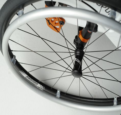
www.sunrisemedical.com

If you are visually impaired, this document can be viewed in PDF format at
www.SunriseMedical.co.uk.

Si vous souffrez de déficience visuelle, ce document peut être consulté en format PDF
sur www.sunrisemedical.fr

Als u een visuele beperking heeft, kan dit document ook worden gelezen in PDF-
formaat op: www.SunriseMedical.nl.

 Wheelchair Components                                                                                     EN
We at SUNRISE MEDICAL have been awarded the ISO-13485 certificate, which affirms the quality of our products at
every stage, from R & D to production. This products meet the requirements in accordance with EC guidelines. Options or
accessories shown are available at extra cost.

 Description du fauteuil                                                                                   FR
We at SUNRISE MEDICAL have been awarded the ISO-13485 certificate, which affirms the quality of our products at
every stage, from R & D to production. Ce produit est conforme aux directives de la Communauté européenne. Les
options ou accessoires illustrés sont disponibles en option.

 Rolstoelonderdelen                                                                                        NL
SUNRISE MEDICAL heeft het ISO 13485 certificaat toegekend gekregen, een bewijs van de kwaliteit van onze
processen in elk stadium, vanaf het onderzoek en de ontwikkeling tot de productie. Deze producten voldoen aan de eisen
in overeenstemming met de EG-richtlijnen. Getoonde opties en accessoires zijn tegen betaling verkrijgbaar.

2                                                                                            Nitrum / Nitrum Hybrid Rev.C
2

         1

         3

         11

         12                                                                                               4

                                                                                                          5
         9

                       10
                                                                                                  7

                                           8                              6

                               EN 04                       FR 31                           NL 58

               1.    Push handles              1.  Poignées de poussée        1.    Duwhandvatten
               2.    Backrest upholstery       2.  Toile de dossier           2.    Spanbanden rug
               3.    Sideguard                 3.  Protège-vêtement           3.    Zijkant
               4.    Seat sling                4.  Toile du siège             4.    Zitmat
               5.    Frame                     5.  Châssis                    5.    Frame
               6.    Castors                   6.  Roues avant                6.    Voorwielen
               7.    Footboard                 7.  Palette                    7.    Voetplaten
               8.    Fork                      8.  Fourche                    8.    Vork
               9.    Quick-release axle        9.  Axe à déverrouillage       9.    Quick release assen
               10.   Wheel locks                   rapide                     10.   Remmen
               11.   Handrim                   10. Freins                     11.   Hoepel
               12.   Rear wheel                11. Main courante              12.   Achterwiel
                                               12. Roue arrière

Nitrum / Nitrum Hybrid Rev.C                                                                                  3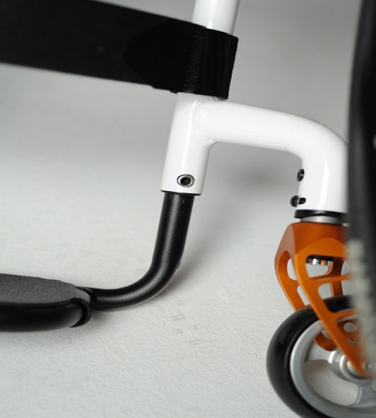
Table of Contents                                                 Definitions

          Table of Contents	                                            4   Definitions of words used in this manual
          Definitions	                                                  4
ENGLISH

          Foreword	                                                     5    Word                 Definition
          Use	                                                          5
          Area of Application.	                                         5                         Advice to the user of potential risk
          1.0 General safety notes and driving limits                   6         DANGER!         of serious injury or death if the
          2.0 Handling	                                                 8                         advice is not followed
          3.0 Transporting the wheelchair	                              8
          4.0 Options 	                                                 8
          Step Tubes	                                                   8
          Brakes	                                                       8                         Advice to the user of a risk of injury
                                                                                   WARNING!        if the advice is not followed
          Suspension System	                                           10
          Hand-Bike Axle Adjustment	                                   11
          Nitrum centre of gravity setting	                            12
          Nitrum Hybrid centre of gravity setting	                     12
          Footplate Adjustment	                                        13                         Advice to user that potential
          Seat	                                                        13         CAUTION!        damage to equipment may occur if
          Castors	                                                     14                         the advice is not followed
          Wheel Alignment	                                             15
          Backrest	                                                    15
          Sideguards	                                                  18         NOTE:           General advice or best practice
          Push handle	                                                 19
          Anti-tip tubes	                                              20
          Crutch Holder	                                               20                         Reference To Additional
          Pelvic Restraint Belt	                                       21                         Documentation
          5.0 Tyres and Mounting	                                      22
          6.0 Maintenance and care	                                    22
          7.0 Disposal / Recycling of Materials	                       23
          8.0 Trouble-shooting	                                        23
          9.0 Transportation	                                          24
          10.0 Nameplate	                                              26
          11.0 Warranty	                                               26
          12.0 Technical Data	                                         27
          13.0 Torque	                                                 30

          NOTE:                                                              NOTE:
          The wheelchairs shown and described in this user guide may         Please keep a note of your local service agent’s address and
          not correspond in every detail exactly to your own model.          telephone number in the space provided.
          However, all instructions are completely relevant, regardless of   In the event of a breakdown, contact them and try to give all
          possible detail differences.                                       relevant details so they can help you quickly.
          The manufacturer reserves the right to alter without notice any
          weights, measurements or other technical data shown in this
          manual. All figures, measurements and capacities shown in this
          manual are approximate and do not constitute specifications.

                                                                             Dealer signature and stamp

          4                                                                                                     Nitrum / Nitrum Hybrid Rev.C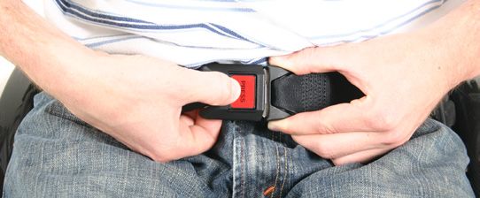
Foreword                                                            Please contact your local, authorised SUNRISE MEDICAL
                                                                    dealer if you have any questions concerning the use,
Dear Customer,                                                      maintenance, or safety of your wheelchair.

                                                                                                                                          ENGLISH
We are very happy that you have decided in favour of a high-        In case there is no authorised dealer in your area,
quality product from SUNRISE MEDICAL.                               or you have any questions about product safety and product
                                                                    recalls, contact Sunrise Medical either in writing or by telephone
This owner's manual will provide numerous tips and ideas so         or find the information on www.sunrisemedical.co.uk
that your new wheelchair can become a trustworthy and reliable
partner in your life.
                                                                             IMPORTANT:
For Sunrise Medical, it is very important that we have a good                DO NOT USE YOUR WHEELCHAIR UNTIL THIS
relationship with our customers. We like to keep you up-to-date              MANUAL HAS BEEN READ AND UNDERSTOOD.
about new and current developments at our company. Keeping
close to our customers means: fast service, as little red tape as
possible, working closely with customers. When you need             Sunrise Medical
replacement parts or accessories, or if you just have a question    Thorns Road
about your wheelchair – we are there for you.
                                                                    Brierley Hill
We want you to be satisfied with our products and service. At       West Midlands
Sunrise Medical we are constantly working to develop our            DY5 2LD
products further. For this reason, changes can occur in our         England
palette of products with regard to form, technology and             Phone: 0845 605 66 88
equipment. Consequently, no claims can be construed from the        Fax:     0845 605 66 89
data or pictures contained in this user’s manual.                   www.SunriseMedical.co.uk

The management system of SUNRISE MEDICAL is certified
to EN ISO 13485 and ISO 14001.

            As the manufacturer, SUNRISE MEDICAL,
            declares that the lightweight wheelchairs
            conform to the Medical Device Regulation
            (2017/745).

NOTE:
General user advice.
Not following these instructions may result in physical injury,
damage to the product or damage to the environment!                  Use
Notice to the user and/or patient: Any serious incident that has    Wheelchairs are exclusively for children and adults who are
occurred in relation to the device should be reported to the        unable to walk or have limited mobility, for their own personal
manufacturer and the competent authority of the Member State        use, when self-propelling and being moved by a third party
in which the user and/or patient is established.                    (pushed by attendant), within the home and outdoors.

                                                                    The maximum weight limit (includes the user and any
B4Me special adaptations                                            weight of accessories fitted to the wheelchair) is marked on
Sunrise Medical strongly recommends that in order to ensure         the serial number label, which is affixed to the Axle Tube
that your B4Me product operates, and performs as intended by        below the seat.
the manufacturer; all the user information supplied with your
B4Me product is read and understood, before the product is first    Warranty can only be taken on if the product is used under the
used.                                                               specified conditions and for the intended purposes.
                                                                    The intended lifetime of the wheelchair is 5 years.
Sunrise Medical also recommends that the user information is        Please DO NOT use or fit any 3rd party components to the
not discarded after reading it, but it is kept safely stored for    wheelchair unless they are officially approved by Sunrise
future reference.                                                   Medical.

Medical Device Combinations                                          Area of Application.
It may be possible to combine this Medical device with one or
more other Medical Device or other product. Information on          The variety of fitting variants as well as the modular design
which combinations are possible can be found at                     mean that it can be used by those who cannot walk or have
www.Sunrisemedical.co.uk. All combinations listed have been         limited mobility e.g. because of:
validated to meet the General Safety and Performance
Requirements, section 14.1 of the Medical Device Regulation         • Paralysis
2017/745.                                                           • Loss of extremity (leg amputation)
                                                                    • Extremity defect deformity
Guidance on the combination, such as mounting, can be found         • Joint contractures/joint injuries
at www.SunriseMedical.co.uk                                         • Illnesses such as heart and circulation deficiencies,
                                                                      disturbance of equilibrium or cachexia as well as for elderly
                                                                      people who still have the strength in the upper body.

                                                                    When considering provision, please also note the body size,
                                                                    weight, physical and psychological constitution, the age of the
                                                                    person, living conditions and environment.

Nitrum / Nitrum Hybrid Rev.C                                                                                                          5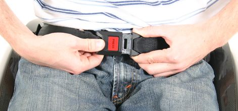
1.0 General safety notes and driving limits
                                                                               • When getting on or off the wheelchair, do not use the
                                                                                 footboards. These should be flipped up beforehand and
ENGLISH

                                                                                 swung to the outside as far as possible. Always position
                                                                                 yourself as close as possible to the place where you wish to
                                                                                 sit.
                                                                               • Only use your wheelchair properly. For example, avoid
                                                                                 travelling against an obstacle without braking (step, kerb
                                                                                 edge) or dropping down gaps.
                                                                               • The wheel locks are not intended to brake your wheelchair.
                                                                                 They are only there to ensure that your wheelchair does not
                                                                                 begin rolling unintentionally. When you stop on uneven
                                                                                 ground, you should always use the wheel locks to prevent
                                                                                 such rolling. Always apply both wheel locks; otherwise, your
                                                                                 wheelchair could tip over.
                                                                               • Explore the effects of changing the centre of gravity on the
                                                                                 behaviour of the wheelchair, for example on inclines, slopes,
                                                                                 all gradients or when overcoming obstacles. Do this with the
                                                                                 secure aid of a helper.
                                                                               • With extreme settings (e.g. rear wheels in the most forward
                                                                                 position) and less than perfect posture, the wheelchair may
                                                                                 tip over even on a level surface.
                                                                               • Lean your upper body further forward when going up slopes
                                                                                 and steps.
                                                                               • Lean your upper body further back when going down slopes
                                                                                 and steps. Never try to climb and descend a slope diagonally.
                                                                               • Avoid using an escalator which may lead to serious injury in
                                                                                 the event of a fall.
                                                                               • Do not use the wheelchair on slopes > 10°. The Dynamic safe
                                                                                 slope is dependent on the chair configuration, the user’s
                                                                                 abilities and the style of riding. As the user’s abilities and style
                                                                                 of riding cannot be pre-determined then the max safe slope
          The engineering and construction of this wheelchair has been           cannot be determined. Therefore this must be determined by
          designed to provide maximum safety. International safety               the user with the assistance of an attendant to prevent
          standards currently in force have either been fulfilled or             tipping. It is strongly recommended that inexperienced users
          exceeded in parts. Nevertheless, users may put themselves at           have anti-tip tubes fitted.
          risk by improperly using their wheelchairs. For your own safety,     • It is possible that potholes or uneven ground could cause this
          the following rules must be strictly observed.                         wheelchair to tip over, especially when riding uphill or
          Unprofessional or erroneous changes or adjustments increase            downhill.
          the risk of accident. As a wheelchair user, you are also part of     • Do not use your wheelchair on muddy or icy ground. Do not
          the daily traffic on streets and pavements, just like anyone else.     use your wheelchair where pedestrians are not allowed.
          We would like to remind you that you are therefore also subject      • To avoid hand injuries do not grab in between the spokes or
          to any and all traffic laws.                                           between the rear wheel and wheel lock when driving the
          Be careful during your first ride in this wheelchair. Get to know      wheelchair.
          your wheelchair.                                                     • In particular when using lightweight metal handrims, fingers
          Before each use, the following should be checked:                      will easily become hot when braking from a high speed or on
          • Quick-release axles on the rear wheels                               long inclines.
          • Velcro on seats and backrests                                      • Riding sideways on to a slope or incline, increases the
          • Tyres, tyre pressure and wheel locks.                                possibility of the wheelchair tipping over sideways.
          Before changing any of the adjustments of this wheelchair, it is     • Only attempt stairs with the help of an attendant. There is
          important to read the corresponding section of the user’s              equipment available to help you, e.g. climbing ramps or lifts,
          manual.                                                                please use them. If there is no such equipment available,
          It is possible that potholes or uneven ground could cause this         then the wheelchair must be tipped and pushed, never
          wheelchair to tip over, especially when riding uphill or downhill.     carried, over the steps (2 helpers). We recommend that users
          When riding forwards over a step or up an incline, the body            over 100 kg in weight do not use this stairway manoeuvre!
          should be leaning forward.                                           • In general, any anti-tip tubes fitted must be set beforehand,
                                                                                 so that they cannot touch the steps, as otherwise this could
                DANGER!                                                          lead to a serious tumble. Afterwards the anti-tip tubes must be
                                                                                 set back to their correct position.
          • NEVER exceed the maximum load of 125 kg, (140 kg with              • Make sure that the attendant only holds the wheelchair using
            “Hybrid-frame” option, 100kg with handbike-axle), for driver         securely mounted parts (e.g. not on the footrests or the
            plus any items carried on the wheelchair. Please note the            sideguards).
            weight information for lighter weight options, which are quoted    • This wheelchair is not designed to be used whilst weight
            separately. If you exceed the maximum load, this can lead to         training and/or when using dumbbells. Only use equipment
            damage to the chair, or you may fall or tip over, lose control       specifically designed for this purpose.
            and may lead to serious injury of the user and other people.       • Do not lift or carry the wheelchair by the backtubes or the
          • When it is dark, please wear light clothing or clothing with         pushhandles.
            reflectors, so that you can be seen more easily. Make sure         • When using the lifting ramp make sure that the anti-tip tubes
            that the reflectors on the side and back of the wheelchair are       fitted are positioned outside the danger area.
            clearly visible. We would also recommend that you fit an           • Secure your wheelchair on uneven ground or when
            active light.                                                        transferring, e.g. into a car, by using the brakes.
          • To avoid falls and dangerous situations, you should first
            practice using your new wheelchair on level ground with good
            visibility.

          6                                                                                                           Nitrum / Nitrum Hybrid Rev.C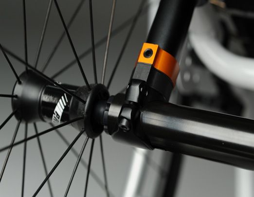
• If and whenever possible, during a journey in a specially fitted    • When easing into the chair from a standing position, make
  vehicle for disabled people, vehicle occupants should use the         sure not to use excessive force. This might lead to
  seats in the vehicle and the appropriate restraint system. This       unnecessary wear and damage to the seat-upholstery and

                                                                                                                                             ENGLISH
  is the only way to ensure that occupants will have the                frame.
  maximum protection if there is an accident. When using              • Always make sure that an attendant is adequately instructed
  safety elements offered by SUNRISE MEDICAL and using a                and trained in handling and supporting an occupant in a
  specially designed safety system, lightweight wheelchairs can         wheelchair. As an attendant, always make sure:
  be used as a seat when being transported in a specially fitted           ○○ To only use intended handles, such as push-handles or
  vehicle. (See the Chapter on “Transportation”).                             the frame-tubes. Never use the footrest, sideguards,
• Depending on the diameter and setting of the castors, as well               wheels or parts of the upholstery as handle
  as the centre of gravity setting of the wheelchair, the castors          ○○ that you have a safe stand and a good grip on the
  may begin to wobble at high speeds. This can lead to the                    handles
  castors being blocked and the wheelchair may tip over.                   ○○ not to lean on the push-handles, as this might tip the
  Therefore, please make sure that the castors are adjusted                   chair backwards
  correctly (see the Chapter "Castors"). In particular, do not             ○○ to always apply the wheel locks for transfers in order to
  travel on an incline without brakes, travel at a reduced speed.             prevent unintended movement of the wheelchair
  We recommend that novice users use anti-tip tubes.                       ○○ to always apply the wheellocks when standing still in
• Anti-tip tubes should prevent the chair tipping over backwards              order to prevent unintended movement of the wheelchair
  unintentionally. Under no circumstances should they take the        As wheelchair-user, always make sure to advise an attendant
  place of transit wheels, and be used to transport a person in a     accordingly.
  wheelchair with the rear wheels removed.                            • Please check wheelchair frame for potential damge after
• When reaching for objects (which are in front of, to the side or      impacts or accidents.
  behind the wheelchair) make sure that you do not lean too far       • When using a new wheelchair or after adjustments affecting
  out of the wheelchair, as if you change the centre of gravity         the user´s position in the wheelchair, frequently check the
  there is a risk of tipping or rolling over. The hanging of            user´s skin for redness or pressure marks.
  additional load (back pack or similar items) onto your chair
  backposts can affect the rearward stability of your chair,
  especially when used in combination with recliner backrests.            WARNING!
  This can cause the chair to tip backwards causing injury.
• Adjustments to your wheelchair, particularly to safety-related      • The effect of the knee-lever brake as well as the general
  components must be carried out by an approved dealer. This            driving characteristics are dependent on tyre pressure. The
  applies to adjustments to wheel locks, anti-tip tubes, backrest       wheelchair is significantly lighter and easier to manoeuvre
  angle and height, lower leg length, COG, lap belt, rear wheel         when the rear wheels are pumped up correctly and both
  toe-in and camber, seat height as well as toe-in and                  wheels have the same pressure.
  directional stability of the castor fork.                           • Make sure that your tyres have sufficient tread! Please note
• When using mobility accessories fitted to the wheelchair such         that you are subject to any and all traffic laws when driving in
  as handbikes, electronic power assist, etc, make sure that            public traffic.
  your wheelchair is fitted with the appropriate castor forks,        • Always be careful with your fingers when working or adjusting
  approved for this use. Please contact your dealer if you have         the wheelchair!
  any questions.
• Do not fit any unauthorized electronic equipment, powered or            WARNING!
  mechanically operated mobility drives, hand-bike or any other
  device that changes the intended use or the structure of the        CHOKING HAZARD – This mobility aid uses small parts which
  wheelchair.                                                         under certain circumstances may present a choking hazard to
• Any combination with other medical devices requires the             small children.
  approval of Sunrise Medical.
• Please note that in certain configurations the wheelchair may
  exceed a width of 700 mm. If this is the case, under certain        The wheelchairs shown and described in this user guide may
  circumstances, it may not be possible to use some or all of         not correspond in every detail exactly to your own model.
  the available escape routes from a building. It may be more         However, all instructions are completely relevant, regardless of
  difficult or impossible to travel on public transport.              possible detail differences.
• Further information and safety instructions can be provided
  by your authorised dealer.                                          The manufacturer reserves the right to alter without notice any
• For thigh amputees you must use anti-tip tubes.                     weights, measurements or other technical data shown in this
• Before setting off, check that your tyre pressure is correct. For   manual. All figures, measurements and capacities shown in this
  rear wheels it should be at least 3.5 bar (350 kPa). The max.       manual are approximate and do not constitute specifications.
  pressure is indicated on the tyre. The knee-lever brakes will
  only work if there is sufficient tyre pressure and if the correct   Sunrise Medical is ISO 13485 certified, which ensures quality at
  setting has been made (see the Chapter on “Brakes”).                all stages of the development and production of our products.
• If the seat and back sling are damaged, you must replace            This product complies with the standards set forth in EU
  them immediately.                                                   directives. Optional equipment and accessories are available at
• Be careful with fire, in particular with burning cigarettes. Seat   extra charge.
  and back slings can be set alight.
• If the wheelchair is subject to direct sunlight for a long period
  of time, then parts of the wheelchair (e.g. frame, legrests,
  brakes and sideguard) may become hot (>41°C).
• Always make sure that the quick-release axles on the rear
  wheels are set properly and lock in. If the button on the quick-
  release axle is not pressed in, the rear wheel cannot be
  removed.

Nitrum / Nitrum Hybrid Rev.C                                                                                                             7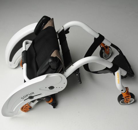
2.0 Handling                                                       Getting into your wheelchair on your own
                                                                                 • Push the wheelchair to a wall or a solid piece of furniture
          Quick-release axles on rear          Fig. 2.1                          • Apply the brakes
          wheel                                                                  • The user can lower themselves into the wheelchair
ENGLISH

          The rear wheels are equipped with                                      • Then position the feet in front of the heel straps
          quick-release axles.                                                      (Fig. 4.1).
          The wheels can thus be installed or
          removed without using tools.                                           Getting out of your wheelchair on your own
          To remove a wheel, simply depress                                      • Apply the brakes
          the quick-release button on the axle                                   • With one hand on the wheel or side guard, the person should
          (1) and pull it out (Fig. 2.1).                                          lean forwards slightly, to transfer the body weight to the front
                                                                                   edge of the seat and then push up to an upright position with
                                                     1
                CAUTION!                                                           both feet firmly on the floor and one foot behind the other (Fig.
                                                                                   4.2).
          Hold the quick-release button on the axle depressed when
          inserting the axle into the frame to mount the rear wheels.            Fig. 4.1                              Fig. 4.2
          Release the button to lock the wheel in place. The quick-release
          button should snap back to its original position.

              3.0 Transporting the wheelchair
          Transporting the wheelchair
          Removing the rear wheels will keep the wheelchair as compact
          as possible. The backrest can be folded by either pushing the
          push-bar upwards or rotating the Twist-lock handle (optional)
          clockwise
                                                                                 Brakes
          Fig. 3.1
                                                                                Fig. 4.3                             Fig. 4.4

                                                                                                                                         3.0 mm

          In this state the wheelchair can be lifted by the frame tubes and
          the seat sling. When transporting the unoccupied wheelchair in
          a vehicle, it should be tied down or strapped in.

              4.0 Options
                                                                                     CAUTION!
              Step Tubes                                                        Braking power can be
                                                                                affected by incorrect fitting and
          Step Tubes                                                            adjustment of the brakes, as well as tyre pressure which is too
          Step tubes are used by attendants to push a wheelchair over an        low.
          obstacle. Simply step on the tube to push a wheelchair, for
          example, over a kerb or step.                                         Wheel Locks
                                                                                Your wheelchair is equipped with two wheel locks. They are
                WARNING!                                                        applied directly against the tyres. To engage, press both wheel
                                                                                lock levers forward against the stops. To release the locks, pull
          Sunrise Medical strongly recommends the use of a step tube on         the levers back to their original positions.
          any model where attendant use is the predominant intended
          use. Damage to the backposts may occur if you constantly use          Braking power will decrease with:
          the backpost without a step tube, as a lever to pull back on to tip   • Worn tyre tread
          the wheelchair.                                                       • Tyre pressure that is too low
                                                                                • Wet tyres
                                                                                • Improperly adjusted wheel locks.

          8                                                                                                           Nitrum / Nitrum Hybrid Rev.C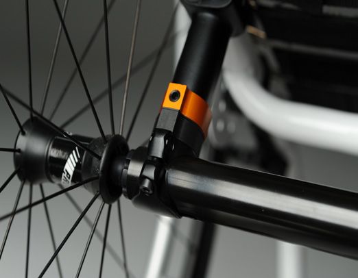
Brakes                                                               The One-arm Wheel Lock
                                                                      The one arm wheel lock is underneath the seat sling and is
                                                                      operated by pulling the brake lever, which is located on the left
The wheel locks have not been designed to be used as brakes
                                                                      or right side, towards the rear, in the direction of the tyre. For
for a moving wheelchair. The wheel locks should therefore never

                                                                                                                                           ENGLISH
                                                                      the brakes to work properly, this must be pulled until it reaches
be used to brake a moving wheelchair. Always use the handrims
                                                                      the stop, (Fig. 4.6.1)
for braking. Make sure that the interval between the tyres and
wheel locks complies with given specifications. To readjust,
                                                                      Adjustment
loosen screw and set the appropriate interval. Then re-tighten
                                                                      To adjust the brake, loose the screws (1) and mount the wheel
the screw, (Fig. 4.3 and 4.4).
                                                                      lock where it will work in a proper way (Fig. 4.6.2).
     CAUTION!
                                                                          CAUTION!
After each adjustment of the rear wheels, check the interval to
                                                                      Incorrect mounting of the one arm wheel lock can lead to
the wheel locks and readjust if necessary.
                                                                      serious injury of the user and other people.
Brake lever extension
The longer lever helps to minimize the effort needed to set the
wheel locks.                                                          Fig. 4.6.1
The brake lever extension is screwed to the brakes. By raising
this, it can be flipped forward (Fig. 4.5).

     CAUTION!
Mounting the wheel lock too close towards the wheel will result
in a higher effort to operate. This might cause the brake lever
extension to break!

Leaning onto the brake lever extension while transferring will        Fig. 4.6.2
cause the lever to break! Splashing water from tires might cause
the wheel lock to malfunction.

     CAUTION!
Incorrect mounting of the wheel lock will result in a higher effort
to operate.
This might cause the wheel lock extension lever to break!

Compact Wheel Lock
Compact wheel locks are underneath the seat sling and are                                      1
operated by pulling the wheel locks towards the rear, in the
direction of the tyre. For the brakes to work properly, this must
be pulled until it reaches the stops, (Fig. 4.6).

     CAUTION!
The mounting bolts for the brakes must not be loosened and/or
re-tightened.

Fig. 4.5                           Fig. 4.6

Nitrum / Nitrum Hybrid Rev.C                                                                                                           9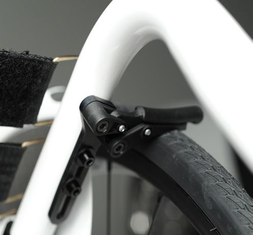
Suspension System
CAUTION!
When turning the 4-Link Rear Suspension, make one change at a
WARNING!
ENGLISH
time and write down each change. This takes patience, but allows
you to understand how each change affects the ride of the
Rear suspension can affect the stability of the wheelchair. To
wheelchair in conjunction with rear suspension.
avoid a fall, use a spotter and/or anti-tip tubes when becoming
familiar with new equipment.
NOTE– The lower shock mount is designed to have a loose feel,
this is by design to allow for proper suspension travel.
1. Tuning the 4-Link Rear Suspension
a. to stiffen the suspension, turn the spring preload adjustor (E)
clockwise (looking up at the suspension system from CAUTION!
underneath the wheelchair). Under no circumstances, loosen the screw connection between
b. to soften the suspension, turn the spring preload adjustor (E) the axle clamp and the shock absorber.
counter-clockwise (looking up at the suspension system from
underneath the wheelchair). 3. Maintenance
The maintenance requirements listed below should be followed
2. Alignment of Suspension Link Arms along with general wheelchair maintenance shown in Section 6.0.
Do not adjust the link arms (F, Fig. 4.10). These are set at the a. d o not apply lubrication to shock end bushings or coils.
factory to ensure proper tracking and performance of the 4-Link b. y ou can apply lubrication to the link ends after cleaning with a
suspension system. mild soap and soft
(see next page). brush.
c. use a soft brush to clear any dirt or debris from coil system.
Setting the toe-in/toe-out to zero (using the factory fitted d. n ever use a high-powered washer for cleaning the 4-Link Rear
adjuster) Suspension.
Loosen the Allen screws (G), (2 per side), that
secure the axle tube on both sides. Observe the ball in the
transparent adjuster in the centre of the axle tube, then turn the
axle tube (C), until the ball is exactly centred at the lowest point
of the adjuster. The toe is now set at zero (Fig. 4.7, 4.10).
Before re-tightening the screws (G), check that
the flat surfaces of the camber adapter in the axle tube protrude
outside the axle tube clamp. The end of the cylindrical camber
adapter should be flush with the end of the axle tube. Tighten
the screws to a torque of 7 Nm
Setting the toe-in/toe-out to zero (using a 90° setting gauge)
Place the entire wheelchair on a flat
horizontal table or ground surface. Loosen the Allen screws (G)
(2 per side) which hold the axle tube on both sides of the axle
tube.
Fig. 4.7 Fig. 4.8
Then put the setting gauge at an angle of exactly 90° (e.g. a C
carpenter’s square) on the flat surfaces of the camber adapter
(D) (Fig. 4.8, Fig. 4.9). Then turn the axle tube until the wrench
surfaces are exactly parallel to the upper surface of the setting
gauge (Fig. 4.8).
Before re-tightening the screws (G), check that
the flat surfaces of the camber adapter in the axle tube protrude
outside the axle tube clamp. The end of the cylindrical camber
adapter should be flush with the end of the axle tube. Tighten D
the screws to a torque of 7 Nm
B
BALL
Fig. 4.9 Fig. 4.10
C
D
F
E
H
PARALLEL I
G
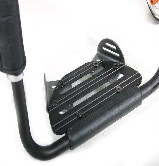
10 Nitrum / Nitrum Hybrid Rev.CHand-Bike Axle Adjustment Fig. 4.10.2
Hand-Bike-Axle
ENGLISH
It is necessary to adjust the hand-bike axle to bias the centre of
gravity rearwards. This allows safe use of a hand-bike
accessory, (Fig. 4.10.1).
DANGER!
Using a hand-bike without the hand-bike axle makes the
wheelchair unstable and can lead to serious injury of the user
and other people.
Fig. 4.10.1
Fig. 4.10.3
Fig. 4.10.4
Hand-Bike Reinforcement Kit
To assemble the hand-bike reinforcement kit:
A
• Insert the nipple at one end of the cable into the receptor at
the front of the frame, (Fig. 4.10.2).
• Insert the nipple at the other end of the cable into the
receptor at the rear of the frame, (Fig. 4.10.3). Fig. 4.10.5
• Insert the tensioner tool, (A), into the cable receptor at the
rear of the frame, (Fig. 4.10.4).
• Move the tensioner tool, (A), upwards until the receptor and
the front tube, (B), just starts to move towards the rear, (Fig.
4.10.5).
• Hold the cable under tension with the tensioner tool and
tighten the screw on the rear cable receptor, (Fig. 4.10.5).
• Repeat the process for the other side. A
WARNING!
The tension of both cables must be checked for tightness B
before and after each use of the hand-bike.
Nitrum / Nitrum Hybrid Rev.C 11Nitrum centre of gravity setting Nitrum Hybrid centre of gravity setting
Remove the rear wheels. Undo both Allen screws (A) on the To adjust the centre of gravity (COG) remove the 2 screws, (A)
bottom of the axle stem (B) on both sides of the wheelchair, and move the bracket into preferred position, (Fig. 4.10.7). Refit
ENGLISH
(Fig. 4.10.6). Then push the complete unit (axle and axle- and tighten the screws (5 Nm).
stems) forwards on the frame, (in terms of the direction of
travel), for a more active COG, or backwards for a more
passive, stable COG. Then re-tighten the screws (A) on both
CAUTION!
sides to a torque of 5 Nm. Now adjust the side guards and
brakes to the new wheel position.
Please note that the tipping behaviour of the wheelchair will
change if the COG has been changed. This may mean that you
CAUTION!
need to use anti-tip tubes.
Please note that the tipping behaviour of the wheelchair will
DANGER!
change if the COG has been changed. This may mean that you
need to use anti-tip tubes.
Only adjust the position of the COG within the markings on the The brakes must be adjusted to the new COG position.
frame tube.
Fig. 4.10.7
DANGER!
A
The brakes must be adjusted to the new COG position.
Fig. 4.10.6
B A
12 Nitrum / Nitrum Hybrid Rev.CFootplate Adjustment Seat
Adjusting The Footrest Adjusting the seat height
ENGLISH
To adjust the rear seat height release the Allen screws (1) (one
WARNING! on each side), that fix the clamp to the axle stem (2). Remove
the spacer (3), to adjust the seat height by -10 mm or add the
• Do not stand on the footboard! Even if the user is sitting in the spacer to increase the seat height by 10 mm.
chair, there is still a risk of tipping over and injury. Tighten the 2 Allen screws to 7 Nm. (Fig. 4.14).
• When transferring, do not stand on the footboard, there is a
risk of tipping over and injury. NOTE:
An adjustment to the castor angle may be necessary when
Releasing the screw (1) will allow you to adjust the footrest to adjusting the rear seat height.
correspond to the length of your lower leg and re-attach the
footrest. The angle of the footrest may be individually adjusted Seat Sling
by loosening screws (2). The side protection (3) on the footrest To tighten the upholstery, please use the straps below the
prevents the feet slipping off accidentally. Make sure that after upholstery.
any adjustment work, all screws are tightened correctly (see the
page on torque) (Fig. 4.11 - 4.12).
Fig. 4.11 Fig. 4.12 Fig. 4.14
3
2
1
1
3
2
High-mount footrest
The high-mount footrest is fitted on the inner part of the frame
and permits a higher footrest position (Fig. 4.13).
Fig. 4.13
Nitrum / Nitrum Hybrid Rev.C 13Castors Anti-Flutter adjustment
Most caster-forks are equipped with an anti-flutter adjustment to
Castor, Castor adapter, Castor fork suppress caster-flutter
ENGLISH
From time to time the wheelchair may veer slightly to the right or Turning the set-screw (Fig. 4.16 - A) on the caster-fork
left or the castors may flutter. This may be caused by the clockwise using an allen-key, will put load on the bearing and
following: reduce caster-flutter.
• Forward and/or reverse wheel motion has not been set
properly. You might notice that the caster-fork does not spin freely but
• The castor angle has not been adjusted properly. with a slight resistance. This has no effect on the driving
• Castor and/or rear wheel air pressure is incorrect; wheels do behaviour of the wheelchair.
not turn smoothly.
The optimum adjustment of the castors is required so that the
wheelchair runs in a straight line.
The castor plates must be re-adjusted, and the wheel locks must CAUTION:
be checked every time the rear wheel position has been altered. When load on the bearing is released by turning the set-screw
counter-clockwise , caster-wheels can be prone to flutter on
medium or higher speeds. If you choose to conduct this
Adjusting the castor adjustment, make yourself familiar with the driving-behaviour of
the wheelchair.
Setting directional stability and fine-tune caster-height
These are works-settings and require special tools- please
contact your dealer for support. DANGER:
Caster-flutter can cause a sudden lock of the caster-wheels on
medium or higher speed, which can cause the user to fall out of
the wheelchair.
Adjusting the caster-fork angle
This adjustment is necessary when changing the front- or rear
seat-height. Fig. 4.16
CAUTION:
Failure to adjust the correct angle can result in caster-flutter,
locking caster wheels and injury of the user.
A
Loosen Allen screws (A) (Fig. 4.15.1). The caster-fork angle can
now be adjusted to the correct position: the flat section of the
fork must be positioned 90° to the ground (Fig. 4.15.2). Once
you have set the correct position, then tighten the allen screws
(A) using the following procedure:
Tighten the outer allen screw first to a torque of 7Nm, than tight-
en the inner allen screw to a torque of 7Nm.
Repeat this procedure up to 6 times until both allen screws are
evenly tightened to a torque of 7Nm.
Fig. 4.15.1 Fig. 4.15.2
A
90°
14 Nitrum / Nitrum Hybrid Rev.CWheel Alignment Backrest
Adjusting the wheel alignment Angle-adjustable back
Remove allen screws (A) on both backrest tubes. Adjust angle
ENGLISH
Important: To achieve the very best movement, the rear wheels
must be adjusted to their optimum position, which means within the hole-pattern (3° increment per hole), insert allen
correctly adjusting the wheel alignment. screws (A) on both sides and tighten to 5Nm (Fig. 4.21).
To do this, measure the distance between both wheels front and
Fig. 4.21
rear to ensure that they are parallel to one another.
The difference between both measurements should not exceed
5 mm.
To adjust the wheels to make them parallel, loosen the screws
and turn the axle sleeve accordingly. Make sure that after any
adjustment work, all screws are tightened correctly (see the
page on torque).
NITRUM tracking adjustment
Setting the toe-in/toe-out to zero
NOTE: A wheelchair with 0° camber cylinders cannot have toe-in A
or toe-out. This setting is necessary only with 3° and 6° camber
cylinders.
The term "toe-in or toe-out" defines how well the rear wheels of
the chair are aligned in relation to the ground. This determines
how well the chair will run. Normal resistance or rolling
resistance is present when toe-in is set to zero.
Folding backrest
To set toe-in/toe-out to zero: Loosen the Allen screw (1) (one on
The backrest is foldable, two versions of the release mechanism
each side), that secures the camber tube clamp. Check the ball
are available:
in the horizontal (2) plane and turn the angle tube (3) until the
• Pushbar- release: push the release bar upwards, hold the
ball is in the centre. Toe-in is now zero.
position and fold the backrest forward
Before tightening the screws (1), check that the camber tube is
• Twist-lock-release : rotate the handle on the crossbar forward,
centred left-to-right. The gap should be the same on both sides,
hold the position and fold backrest forward. The handle can
or there should be no gap at all. Tighten the screws to 7 Nm.
only be rotated in the forward direction.
(Fig. 4.17 - 4.19).
A double-locking option is available on the backrest- if the
Adjusting the rear wheelbase width: wheelchair is equipped with this option, the backrest will lock in
The rear wheelbase is defined as the distance between the the flat-folded position.
upper side of the rear wheels and the backrest tubes, and is To unfold the backrest, either push the pushbar upwards or
represented by factory setting (125 mm). This has to be rotate the twist-lock handle forward.
increased if a larger gap between the tyres and the optional The locking position (angle) of the folded backrest can be
height-adjustable armrests has to be created (Fig. 4.20). adjusted : remove allen-screw (B) on both sides (Fig. 4.22), set
NOTE:When adjusting the rear wheelbase, adjust first one the desired locking angle by chosing the corresponding hole
wheel then the other. If both sides are loosened at the same within the hole-pattern (C) (Fig. 4.23) and re-tighten allen screws
time, this will alter the toe-in/toe-out adjustment. To adjust the (B) on both sides to 5Nm
rear wheelbase, the parts of the camber (4) move telescopically
into or out of the camber tube (5), and lock into place when they Fig. 4.22 Fig. 4.23
reach the end. Loosen screw (6) (located closest to the camber
tube) on the left side of the chair. Move the axle receiver inwards
or outwards to achieve the desired wheelbase. Tighten the
screws to 7 Nm. Repeat this procedure on the right side of the
chair and adjust the gap so that it is the same amount as on the
left side.
Fig. 4.17 Fig. 4.18 B
C
1
Fig. 4.19 3 Fig. 4.20
5
4
BALL 2 6
Nitrum / Nitrum Hybrid Rev.C 15Height-adjustable backrest Adjusting the backrest upholstery
The backrest may be set to various back heights, in 25 mm Adjust the tension of the backrest´s top-belt
increments. The adjustment ranges are 250 - 300 mm, 300 -
350 mm, 350 - 400 mm and 400 - 450 mm. Release the screw -- Tear both velcroed halves of the top belt apart (Fig.4.25)
ENGLISH
(1) and set the backrest to the desired height. Tighten up the -- Tension the top-belt or remove tension. Once the desired
screws again to 5Nm. (Fig. 4.24) strain is set, velcroe both halves back together
-- In case of the top-belt laterally protruding over the push-
handles, the belt can be cut to size with a pair of scissors.
Fig. 4.24 Cut the belt between the grey stitchings. The stitching will
prevent the belt from fraying, Melt the cutting edge of the
belt for additional fray-protection. (Fig.4.26)
Fig. 4.25
1
Fig. 4.26
Note for wheelchairs with fold-down push-handles
Do not use the velcro-laces around the push-handles to set the
strain of the belt (Fig.4.27). Those must be velcroed to the top-
belt using their full length.
Fig. 4.27
16 Nitrum / Nitrum Hybrid Rev.CAdjust the tension of the backrest-belts LED lights
-- Tension of the backrest-belts can be continuously adjusted The optional LED lights are mounted to the caster-links using
using the velcro-laces an adhesive tape and an allen screw.
-- Ex-works, the velcro-laces overlap by 20mm (Fig.4.28). This The control-Box (Fig. 4.29) is clipped to the calf-straps and can
ENGLISH
overlap allows you to adjust slack on the backrest- be removed for charging.
upholstery -- Switching the lights on: by pushing the button A on top of
-- When further tensioning the belts, the ends can laterally the control-Box, you can cycle through operating-modes of
protrude. In these cases, the belts can be cut to size with a the LEDs:
pair of scissors. Cut the belt between the black stitchings.
The stitching will prevent the belt from fraying, Melt the
cutting edge of the belt for additional fray-protection. 1. Full power mode
2. Low-power mode
Fig. 4.28 3. Flash-mode
20mm
4. Off
Remove the control-box from the calf-strap:
Detach cables on the sides by gently pulling the pins out of the
connectors (C ). Now pull the control-box upwards to remove it
from the calf-strap.
Charge the battery:
Connect the USB-cable to the connector (B) on the front-side of
the control-Box. Use a standard USB-charger or your
Computer´s USB-port to charge the battery.
Battery-type Lithium-Ion
Nominal capacity 2600mAh
Nominal voltage 3,6V
Charging-time 3hrs
CAUTION! Fig. 4.29
When folding the backrest down, please make sure that your
fingers do not get caught.
CAUTION!
Please note that the tipping behaviour of the wheelchair will
change if the backrest angle or backrest upholstery has been
changed. This may mean that you need to use anti-tip tubes.
Nitrum / Nitrum Hybrid Rev.C 17Freestyle Back Sideguards
The Freestyle back can be adjusted in height, depth and angle
to provide maximum comfort and support. Single Post Height-Adjustable Armrests (Fig. 4.34 - 4.37).
ENGLISH
1. Assembly
Height adjustment: a. s
lide the outer armpost into the receiver mounted to the
Remove the back cushion to gain access to the adjustment wheelchair frame.
hardware. Loosen the 4 screws (1) using a 4 mm hex key and b. the armrest will automatically lock into place.
move the back shell up or down to the desired height. Tighten
the screws to lock the adjustment and re-install the back 2. Height adjustment
cushion. a. r otate height release lever (2) to second stop.
b. s lide armrest pad up or down to desired height.
Fine Depth and Height adjustment c. r eturn lever to locked position against arm post.
The Freestyle back adjustment system provides a maximum of d. p ush arm pad (4) until upper arm post locks firmly into
25 mm fine depth combined with a fine height adjustment . place.
Loosen the screws (2) using a 8 mm hex key and rotate the 3. Removing the armrest
back shell to the desired position. Tighten the screws with 20 a. p
ull lever 3 and lift entire arm.
Nm to lock the adjustment.
4. Replacing Armrest
Angle adjustment a. s lide armrest back into receiver until arm latches in place.
The Freeestyle back adjustment system allows the adjustment
of the backrest angle. Loosen the screws (3) using a 8 mm hex Armrest Receiver Attachment
key and rotate the back shell to the desired position. Tighten the (Fig. 4.34 - 4.37).
screws with 20 Nm to lock the adjustment. Adjusting Armrest Receiver Fit
To tighten or loosen the fit of the outer armpost in the receiver:
In case some attendant support is required the removable push 1. L
oosen the four receiver adjustment bolts (9) on the sides of
handles can be screwed into position A. the receiver.
2. W
ith the armrest in the receiver (7), squeeze the receiver to
achieve the desired fit.
WARNING! 3. Tighten the four bolts (9). (16.3 Nm)
Always make sure that the push handles are screwed in Position Adjustment
completely. 1. L
oosen the two clamp bolts (10) until clamp is loose.
2. S
lide armrest receiver to desired position.
3. Tighten
WARNING!
The Freestyle back is not approved for using the wheelchair as
a seat in a car during transport.
Fig. 4.34 - 4.37 Parts key
1. Outer armpost 6. Sideguard
2. Height Release Lever 7. Receiver
3. Release lever 8. Clamp
4. Armrest Pad 9. Receiver adjustment bolts
5. Transfer bar 10. Clamp bolts
Fig. 4.30 Fig. 4.31 Fig. 4.34 4 Fig. 4.35
7
1 5
1 3 6 8
2
1 9
9 10
2 7 3
9 10
Fig. 4.32 Fig. 4.33 Fig. 4.36 Fig. 4.37
A
20 Nm
9
20 Nm
7
18 Nitrum / Nitrum Hybrid Rev.CCentral support Push handle
Installation: Slide the arm post into the receiver, located on the Height-adjustable push handles
wheelchair frame, until it stops
ENGLISH
These handles are secured with pins to prevent them from
sliding out unintentionally. Opening the quick-release lever (1)
Height adjustment:
makes it possible to adjust the height of the push handles (2) to
Slide the armrest post out of the receiver.
meet your individual needs. As you move the lever, you will hear
Adjust the position of the height adjustment bracket (1) by
a locking mechanism; you may now easily position the push
removing the screw (2) and moving it to the desired position.
handle as desired. The nut on the tension lever determines how
Re-fit the screw and tighten it.
tightly the push handles are clamped into place. If the nut is
Slide the arm rest post back into the receiver, (Fig. 4.37.1).
loose after adjusting the tension lever, the push handle will also
be too loose. Turn the push handle from side to side before use
Armpad Position:
to make sure that it is clamped securely enough into place. After
The armpad position can be adjusted by releasing the screws
adjusting handle height, always clamp the tension lever (1)
(3), then moving the arm pad to the desired position. Re-tighten
securely into place. If the lever is not secure, injuries could result
the screws, (Fig. 4.37.1).
when ascending stairs. (Fig. 4.38).
Adjusting Armrest Receiver NOTE – If the height-adjustable push handles are not fitted
The tightness of the armrest receiver can be adjusted (tightened properly, there is a risk that these will develop "play" or that they
/loosened) by means of the 2 screws (1) - (Fig. 4.37.2). move out of position. Please make sure that the relevant screws
are tightened correctly.
Folding push-handles
If the push handles are not in use, they can be folded down by
depressing the button (2). When they are needed again, simply
flip them back up until they click into place. (Fig. 4.39).
Fig. 4.37.1 Fig. 4.37.2 Fig. 4.38 Fig. 4.39
2
3
1 1 2
1 2
Nitrum / Nitrum Hybrid Rev.C 19Anti-tip tubes Active Anti-Tip tubes For Sport
To remove the active anti-tip tubes for sport, press the button of
the quick release pin and pull it out. Now pull out the tube from
WARNING!
ENGLISH
the anti-tip receiver, (4.40.2 - 4.40.3).
Sunrise Medical recommends anti-tip tubes for all chairs. When
fitting anti-tip tubes, use a torque of 7 Nm.
1. Slotting the anti-tip tubes into the clamp:
a. press the rear button on the anti-tip tube on the anti-tip tube
adaptor, so that both release pins are drawn inwards.
b. slot the anti-tip tubes (1) into the anti-tip tube adapter. Fig. 4.40.2
c. turn the anti-tip tubes downwards until the release pin locks
into the clamp.
d. fit the second anti-tip tubein the same way.
2. Adjusting Anti-Tip Tubes
To achieve the correct ground
clearance of approx. 1" to 2" (25 Fig. 4.40
mm to 50 mm), the anti-tip tubes
must be raised or lowered.
Press the anti-tip tube release
button, so that both release pins
are drawn inwards. Move the
inner tube up or down to slot into Fig. 4.40.3
the height holes provided.
Release the button. Fit the
second anti-tip tube in the same
way. Both wheels should be at
the same height. (Fig. 4.40).
DANGER!
Sunrise Medical Recommends Use Of Anti-Tip Tubes:
If the anti-tip tubes are not fitted, or have been fitted incorrectly,
there is a risk of tipping over and of injury.
Active Anti-Tip tube/Flip Up
The active anti-tip tube is mounted on the left or right side of the
axle tube. By pushing it towards the axle tube, it can be flipped
downwards for operation, (Fig. 4.40.1).
WARNING!
Make sure that the anti-tip tube will lock in the final position. An
unlocked active anti-tip tube can lead to serious injury of the
user.
Crutch Holder
Crutch Holder
This device permits crutches to be transported directly on a
wheelchair. It has a Velcro loop to fasten crutches or other aids.
CAUTION!
Never try to use or even remove the crutches or other aids while
Fig. 4.40.1
moving.
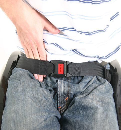
20 Nitrum / Nitrum Hybrid Rev.CPelvic Restraint Belt The lap belt should be fixed so that the belt sits at an angle of 45
degrees across the user’s pelvis. The user should be upright
and be as far back as possible in the seat when correctly
DANGER! adjusted. The lap belt should not allow the user to slip down in
ENGLISH
the seat. (Fig. 4.44)
• Before using your wheelchair ensure the lap belt is worn.
• The lap belt must be checked on a daily
• basis to ensure it is free from any obstruction or adverse
wear.
• Always make sure that the lap strap is correctly secured and
Fig. 4.43 Fig. 4.44
adjusted prior to use. If the strap is too loose it could cause
the user to slip down and risk suffocation or cause serious
injury.
The lap belt is fitted to the wheelchair as shown in the
illustrations. The seat belt comprises 2 halves. They are fitted
using the existing seat stay retaining bolt fitted through the
eyelet on the belt. The belt is routed under the rear of the side
panel. (Fig. 4.41)
Adjust the belt position so buckles are in the centre of the seat.
(Fig. 4.42)
Fig. 4.41 Fig. 4.42
To fasten buckle: To release belt:
Firmly push male buckle Press exposed sides of male
into female buckle. buckle and push towards
centre whilst gently pulling
apart.
WARNING!
Adjust lap belt to suit the user’s needs as follows: • If in doubt about the use and operation of the lap belt then
To reduce the belt To increase the belt length ask your healthcare professional, wheelchair dealer, carer or
length attendant for assistance.
• If you want to retrofit a lap belt, then please contact your
authorised Sunrise Medical dealer.
• The lap belt must be checked on a daily basis to ensure it is
adjusted correctly and free from any obstruction or adverse
wear.
• Sunrise Medical does not encourage the transportation of any
person in a vehicle using this lap belt as a method of restraint.
Please see Sunrise Medical transit booklet for further
advice on transportation.
Maintenance:
Check lap belt and securing components at regular intervals for
Feed free belt Feed free belt through slide adjusters any sign of fraying or damage. Replace if necessary.
back through male and male buckle to provide more belt
buckle and slide length.
adjusters. WARNING
Ensure belt is not
The lap belt should be adjusted to suit the end user as detailed
looped at male above. Sunrise Medical recommends that the length and fit of
buckle. the belt be checked on a regular basis to reduce the risk of the
end user inadvertently re-adjusting the belt to an excessive
When fastened check space between the pelvic restraint belt length.
and user. When correctly adjusted it should not be possible to
insert more than the flat of the hand between the lap belt and the
user. (Fig. 4.43)
Nitrum / Nitrum Hybrid Rev.C 215.0 Tyres and Mounting 6.0 Maintenance and care
Solid rubber tyres are standard. • Check the tyre pressure every 4 weeks. Check all tyres for
With pneumatic tyres always make sure that the tyres have the wear and damage.
ENGLISH
correct air pressure, as otherwise the performance of the • Check the brakes approximately every 4 weeks to make sure
wheelchair may be affected. If the tyre pressure is too low, rolling that they are working properly and are easy to use.
resistance will increase, requiring more effort to move the chair • Change tyres as you would an ordinary bicycle tyre.
forward. Low tyre pressure also has a negative impact on • All of the joints that are critical to using your wheelchair safely
manoeuverability. If the tyre pressure is too high, the tyre could are self-locking nuts. Please check every three months to
burst. The correct pressure for a given tyre is printed on the make sure that all bolts are secure (see the section on torque).
surface of the tyre itself. Safety nuts should only be used once and should be replaced
after use.
Tyres can be mounted the same way as an ordinary bicycle tyre. • Please use only mild household cleansers when your
Before installing a new inner tube, you should always make sure wheelchair is dirty. Use only soap and water when cleaning
that the base of the rim and the interior of the tyre are free of the seat upholstery.
foreign objects. Check the pressure after mounting or repairing a • You should only use genuine parts approved by Sunrise
tyre. It is critical to your safety and to the wheelchair’s Medical. Do not use parts from other manufacturers, that have
performance that regulation air pressure be maintained and that not been by authorised by Sunrise Medical.
tyres are in good condition. • If your wheelchair should ever get wet, please dry it
afterwards.
• A small amount of sewing-machine oil should be applied to
quick-release axles approximately every 8 weeks. Depending
on the frequency and type of use, we recommend taking your
wheelchair to your authorised dealer every 6 months to have it
inspected by trained personnel.
• If you want to store the wheelchair for a long period of time,
then no further measures are required. Make sure that the
wheelchair is stored at room temperature in a dry place which
is protected from strong sunlight. Before using it again, the
wheelchair should be checked by an authorised dealer.
CAUTION!
Sand and sea water (or salt in the winter) can damage the
bearings of the front and rear wheels. Clean the wheelchair
thoroughly after exposure.
The following parts can be removed and sent back to the
manufacturer/dealer for repair:
• Rear wheels
• Armrest
• Anti-Tip tubes
These components are available as spare parts. For further
information, please see the spare parts catalogue.
Hygiene measures when being re-used:
Prior to the wheelchair being re-used, it must be carefully
prepared. All surfaces which come into contact with the user
must be treated with a disinfection spray.
To do this, you must use a disinfectant from the DGHM list, e.g.
Antifect Liquid (Schülke & Mayr) for rapid alcohol-based
disinfection for medical products and medical devices, which
must be disinfected quickly.
Please pay attention to the manufacturer’s instructions of the
disinfectant you are using.
In general, a complete disinfection cannot be guaranteed on
seams. We therefore recommend that you dispose of seat and
back slings to avoid microbacterial contamination with active
agents according to § 6 infection protection law.
CAUTION!
• Excessive use of chemical or use of incorrect chemicals can
lead to corrosion or degradation of materials used
• Body-fluids can lead to corrosion or degradation of materials
used. Make sure to clean and disinfect all parts of the
wheelchair after contact with body-fluids.
22 Nitrum / Nitrum Hybrid Rev.C7.0 Disposal / Recycling of Materials 8.0 Trouble-shooting
If the wheelchair has been made available to you free of Wheelchair pulls to one side
charge, then it does not belong to you. If it is no longer required, • Check tyre pressure
ENGLISH
then follow the instructions to return it as given by the • Check to make sure wheel turns easily (bearings, axle)
organisation that made the wheelchair available to you. • Check the castor angle
In the following section, there is a description of the materials • Check to make sure both castors are making proper contact
used on the wheelchair, in view of the disposal or recycling of with the ground.
the wheelchair and its packaging.
Particular regulations with regard to disposal or recycling may Castors begin to wobble
be in force locally and these must be taken into account when • Check the castor angle
performing disposal. (This can include the cleaning or • Check to make sure all bolts are secure; tighten if necessary
decontamination of the wheelchair prior to disposal). (see the section on torque)
• Check to make sure both castors are making proper contact
Aluminium: Castor forks, wheels, sideguards for the chassis, with the ground.
armrest frame, footrest, push handles
Wheelchair / Cross-tube assembly does not snap into
Steel: Fixing points, quick-release axle position in the seat saddle
• Chair is still new, i.e., the seat or backrest upholstery is still
Plastic: Handgrips, tube plugs, castor wheels, footplates,
very stiff. This will improve with time.
armpads and 12” wheel/tyre
Wheelchair is difficult to fold up:
Packaging: Plastic bags made of soft polyethylene, cardboard
• Adjustable backrest upholstery is too stiff. Loosen it
Upholstery:Woven polyester with PVC coatings and expanded accordingly.
combustion modified foam.
Wheelchair squeaks and rattles
Disposal or recycling should be done through a licensed agent • Check to make sure all bolts are secure; tighten if necessary
or authorised place of disposal. Alternatively your wheelchair (see the section on torque)
may be returned to your dealer for disposal. • Apply small amount of lubrication to spots where movable parts
come into contact with one another
Battery for LED Lights: Lithium Ion battery (hazardous
product) Wheelchair begins to wobble
Electrical and electronic equipment need to be disposed of • Check angle at which castors are set
separately to general household waste at specific state- • Check tyre pressure
provided locations. The correct disposal and separate collection • Check to see if rear wheels are adjusted differently.
of used appliances serves to prevent potential damage to health
and the environment. It is a requirement for the re-utilisation
and recycling of used electrical and electronic equipment.
Detailed information on the disposal of your used equipment
can be obtained from your local authority, your waste disposal
service, the specialist dealer from which you purchased the
product, or your sales contact.
Nitrum / Nitrum Hybrid Rev.C 23You can also read