Krypton F 000690975.02 - Lifestyle & Mobility
←
→
Page content transcription
If your browser does not render page correctly, please read the page content below
Wheelchair
Fauteuil roulant
Rolstoel

                   Directions for use

Krypton F
                   Notice d’utilisation
                   Gebruikershandleiding

                                      000690975.02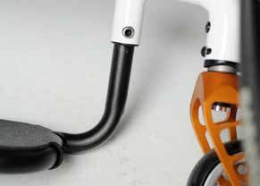
www.sunrisemedical.com

IF YOU ARE VISUALLY IMPAIRED, THIS DOCUMENT CAN BE VIEWED IN PDF
FORMAT AT WWW.SUNRISEMEDICAL.CO.UK

SI VOUS SOUFFREZ DE DÉFICIENCE VISUELLE, CE DOCUMENT PEUT ÊTRE
CONSULTÉ EN FORMAT PDF SUR WWW.SUNRISEMEDICAL.FR

ALS U VISUEEL GEHANDICAPT BENT KAN DIT DOCUMENT OOK WORDEN
GELEZEN IN PDF-FORMAAT OP: WWW.SUNRISEMEDICAL.NL

 Wheelchair Components                                                                                                        EN
We at SUNRISE MEDICAL have been awarded the ISO-13485 certificate, which affirms the quality of our products at every stage, from R&D to
production. This products meet the requirements in accordance with EC guidelines. Options or accessories shown are available at extra cost.

 Description du fauteuil                                                                                                      FR
Nous, la société SUNRISE, sommes certifiés ISO 13485, ce qui garantit la qualité de nos produits à tous les stades, du développement jusqu'à
la production. Ce produit est conforme aux directives de la Communauté européenne. Les options ou accessoires illustrés sont disponibles en
option.

 Rolstoelonderdelen                                                                                                           NL
SUNRISE MEDICAL heeft het ISO 13485 certificaat toegekend gekregen, een bewijs van de kwaliteit van onze processen in elk stadium, vanaf
het onderzoek en de ontwikkeling tot de productie. Deze producten voldoen aan de eisen in overeenstemming met de EG-richtlijnen. Getoonde
opties en accessoires zijn tegen betaling verkrijgbaar.

Krypton F                                                            2                                                                Rev.B
07                                   34                                            61

1. Push handle                    1. Poignée de poussée                             1. Duwhandvat
2. Backrest sling                 2. Toile de dossier                               2. Rugleuning met band
3. Sideguard                      3. Protège-vêtement                               3. Zijkant
4. Seat sling                     4. Toile du siège                                 4. Zitmat
5. Footrest                       5. Repose-pieds                                   5. Voetsteun
6. Castors                        6. Roues avant                                    6. Voorwielen
7. Footplate                      7. Palette                                        7. Voetenplaat
8. Fork                           8. Fourche                                        8. Vork
9. Quick-release axles            9. Axes à déverrouillage rapide                   9. Quick-Release assen
10. Wheel locks                   10. Freins                                        10. Remmen
11. Handrim                       11. Main courante                                 11. Hoepel
12. Rear wheel                    12. Roue arrière                                  12. Achterwiel

                          1                                         2

                                                                        3
                     12

                                                                                4

                     11

                     10

                     9

                                                                                         5

                                                                                     6

                              8                                             7

Krypton F                                        3                                                           Rev.B
mm
° kg
1050 760 1020 500
770 520 690 220
MAX.
550 500 567
430 340 540
MIN.
MAX.
475 500
250 320
MIN.
880 MAX.
+130
+40
---
MIN.
MAX.
10° 10° 10°
0° 0° 0°
MIN.
MAX.
15° 103° 103°
0° 75° 92°
MIN.
MAX.
5.8 ---- 110
8.3 2.1 KG
--- ---
MIN.
Krypton F 4 Rev.Bmm
mm mm
430 370-430
111 mm 440 370-440
450 370-450
A
450 370-450
123 mm 460 370-460
470 370-470
3” (76 mm)
470 370-470
111 mm 480 370-480
490 380-490
B
490 380-490
123 mm 500 390-500
510 400-500
440 370-440
450 370-450
111 mm
460 370-460
470 370-470
A
450 370-450
460 370-460
123 mm
470 370-470
480 370-480
4” (102 mm)
480 370-480
490 380-490
111 mm
500 390-500
510 400-500
B
490 380-490
500 390-500
123 mm
510 400-500
520 410-500
460 370-460
111 mm 470 370-470
480 370-480
A
470 370-470
123 mm 480 370-480
490 380-490
5” (127 mm)
500 390-500
111 mm 510 400-500
520 410-500
B
510 400-500
123 mm 520 410-500
530 420-500
Krypton F 5 Rev.Bmm
mm mm
480 370-480
A 490 380-490
500 390-500
6” (152 mm) 123 mm
520 410-500
B 530 420-500
540 430-500
470 370-470
A 480 370-480
490 380-490
4” (102 mm)
510 400-500
B 520 410-500
530 420-500
480 370-480
A 490 380-490
500 390-500
5” (127 mm) Frogleg
520 410-500
B 530 420-500
540 430-500
490 380-490
A 500 390-500
510 400-500
6” (152 mm)
530 420-500
B 540 430-500
550 440-500
Krypton F 6 Rev.BM5 = 5.0 Nm
M6 = 7.0 Nm
M8 = 10.0 Nm Nm
ENGLISH
7 Nm
7 Nm
7 Nm
5 Nm
25 Nm
7 Nm
5 Nm
5 Nm 3 Nm
TO AVOID
DAMAGE OF 5 Nm
CARBON TUBE
3 Nm
ENSURE THAT
SPACER IS
MOUNTED
5 Nm 5 Nm 5 Nm 5 Nm
3 Nm
7 Nm 8 Nm
3 Nm
5 Nm
CAUTION!
Some of the screws that are used in manufacture have a thread lock (blue dot on the threads) and can be used up to
three times, then they must be replaced by new screws. Alternatively, you can put Loctite™ 243 threadlock on the screws
and re-fit them.
Krypton F 7 Rev.BForeword Use
Dear Customer, Wheelchairs are exclusively for an adult or child who is
ENGLISH
unable to walk or has limited mobility, for their own
We are very happy that you have decided in favour of a
personal use, when self-propelling and use with help
high-quality product from SUNRISE MEDICAL.
(pushed by attendant) within the home and outdoors.
This owner's manual will provide numerous tips and ideas
so that your new wheelchair can become a trustworthy The maximum weight limit (includes both the user
and reliable partner in your life. and any weight of accessories fitted to the
wheelchair) is marked on the serial number label,
Maintaining close ties to our customers means a lot to us
which is affixed to the cross-tube or cross-brace
at Sunrise Medical. We like to keep you up-to-date about
under the seat.
new and current developments at our company. Keeping
close to our customers means: fast service, as little red
Warranty can only be issued if the product is used under
tape as possible, working closely with customers. When
the specified conditions and for the intended purpose.
you need replacement parts or accessories, or if you just
The intended lifetime of the wheelchair is 5 years.
have a question about your wheelchair – we are there for
NO NON-STANDARD PARTS are to be fitted, other than
you.
those officially approved by Sunrise Medical.
We want you to be satisfied with our products and
service. At Sunrise Medical we are constantly working to The load-bearing components of this wheelchair are
develop our products further. For this reason, changes manufactured from carbon (correct designation: carbon
can occur in our palette of products with regard to form, fibre reinforced plastic or CFRP). Carbon fibre is a high-
technology and equipment. Consequently, no claims can strength material that is used for conditions requiring
be construed from the data or pictures contained in this extreme load-bearing capacity with minimal weight.
user’s manual. Our carbon components are manually produced -
irregularities in the weave, unevenness in the surface or
The management system of SUNRISE MEDICAL is
small air pockets are purely visual and have no impact on
certified to EN ISO 9001, ISO 13485 and ISO 14001.
stability.
As the manufacturer, SUNRISE MEDICAL, Carbon has some different features compared to metal or
declares that the lightweight wheelchairs other plastics which should be considered for normal use.
conform to the 2017/745/EEC 2007/47/EEC
guideline. CAUTION!
Please contact your local, authorised SUNRISE
Carbon can be damaged from overloading (impacts or
MEDICAL dealer if you have any questions concerning
shocks which go beyond usual use such as: Falls, tipping
the use, maintenance, or safety of your wheelchair.
over or dropping the wheelchair. Overloading may
In case there is no authorised dealer in your area, or you damage the carbon fibres or lead to delamination
have any questions, contact Sunrise Medical either in (separation of the fibre layers or separation of the fibres
writing or by telephone. from the resin).
Often, this damage cannot be identified externally and
Sunrise Medical
may lead to reduced load-bearing capability or breaking
Thorns Road
of components in extreme cases.
West Midlands
DY5 2LD
England
Phone: 0845 605 66 88
Fax: 0845 605 66 89
www.SunriseMedical.co.uk
IMPORTANT:
DO NOT USE YOUR WHEELCHAIR UNTIL THIS
MANUAL HAS BEEN READ AND
UNDERSTOOD.
Krypton F 8 Rev.BDANGER! Area of Application.
• After an accident, fall or dropping the wheelchair, it The variety of options as well as the modular design
ENGLISH
should no longer be used for safety reasons and should means that it can be used by those who cannot walk or
be sent to Sunrise Medical for inspection. have limited mobility because of:
• The wheelchair should be regularly inspected for
damage (cracks, discolourations, etc.). • Paralysis
• If the surface of the carbon components is damaged • Loss of extremity (leg amputation)
(indents or scratches which are deeper than the varnish • Extremity defect deformity
layer) then the wheelchair should be sent to Sunrise • Joint contractures/joint injuries
Medical for inspection. • Illnesses such as heart and circulation deficiencies,
• During transportation (especially when traveling by air), disturbance of equilibrium or cachexia as well as for
ensure that the wheelchair does not come into contact elderly people who still have strength in the upper body.
with other items of luggage. Under no circumstances
may luggage be loaded onto the wheelchair. Ensure When considering provision, please also note the body
that the wheelchair is firmly secured for slipping. size, weight, physical and psychological constitution, the
• Pay attention to creaking noises when using the age of the person, living conditions and environment.
wheelchair as these could indicate damage to the
fibre structure. If applicable send to the wheelchair to
Sunrise Medical for inspection.
• Replace damaged components immediately - damage
to carbon components cannot be repaired.
• Accessories from third party suppliers such as
handbikes, front wheels, or other non-standard fittings,
are not permitted.
• Do not exceed the prescribed torque for all clamps and
screws.
• Never attach any extensions using clamps or screws.
• Never mechanically alter or drill the carbon
components.
• Never expose the wheelchair to high temperatures
(such as for example as may happen to vehicles
parked in the sun) or store near to heat sources.
• Clean the carbon components exclusively with a damp
cloth and clear, cold or lukewarm water, or with added
detergent if required.
• Never use any type of solvent or solvent-based cleaner,
alcohol or acetone. Do not use any polish or abrasive
varnish cleaner.
Krypton F 9 Rev.BTable of Contents 1.0 Definitionen
Definitions of words used in this manual
Foreword 8
ENGLISH
Use 8 Word Definition
1.0 Definitionen 10
2.0 General safety notes and driving limits 11 Advice to the user of potential risk of
3.0 Guarantee 14 DANGER! serious injury or death if the advice
4.0 Handling 15 is not followed
5.0 Quick Release Wheels 16
6.0 Options 16
6.1 Step Tubes 16 Advice to the user of a risk of injury
WARNING! if the advice is not followed
6.2 Wheel locks 16
6.3 Foot rests 18
6.4 Seating 20
6.5 Castors 22 Note to user that potential damage
6.6 Backrest 23 CAUTION! to equipment may occur if the
6.7 Headrests 23 advice is not followed
6.8 Wheel Alignment 24
6.9 Sideguards 25
6.10 Push handles 26 NOTE: General advice or best practice
6.11 Crutch holder 27
6.12 Anti tips 27 Reference To Additional
6.13 Stabilizing Bar 28 Documentation
6.14 Transit Wheels 28
6.15 Pelvic Restraint Belt 29 NOTE:
7.0 Daily Checks 31 • The wheelchairs shown and described in this user
8.0 Tyres and mounting 31 guide may not correspond in every detail exactly to your
own model. However, all instructions are completely
9.0 Maintenance and care 31
relevant, regardless of possible detail differences.
10.0 Trouble shooting 32 • Contact your authorised dealer for further information
11.0 Disposal / Recycling of Materials 32 and safety instructions.
12.0 Name Plate 33 • The manufacturer reserves the right to alter without
13.0 Technical Data 33 notice any weights, measurements or other technical
data shown in this manual. All figures, measurements
and capacities shown in this manual are approximate
and do not constitute specifications.
NOTE:
• Please keep a note of the address and telephone
number of your nearest service centre in the space bel
ow.
• In the event of a breakdown, contact them and try to
give all relevant details so they can help you quickly.
Unterschrift und Stempel des Fachhändlers
Krypton F 10 Rev.B2.0 General safety notes and driving limits
• When it is dark, please wear light clothing or clothing
with reflectors, so that you can be seen more easily.
ENGLISH
Make sure that the reflectors on the side and back
of the wheelchair are clearly visible. We would also
recommend that you fit an active light.
• To avoid falls and dangerous situations, you should first
practice using your new wheelchair on level ground with
good visibility.
• When getting on or off the wheelchair, do not use the
footboards. These should be flipped up beforehand and
swung to the outside as far as possible. Always position
yourself as close as possible to the place where you
wish to sit.
• Only use your wheelchair properly. For example, avoid
travelling against an obstacle without braking (step, kerb
edge) or dropping down gaps.
• The wheel locks are not intended to brake your
wheelchair. They are only there to ensure that your
wheelchair does not begin rolling unintentionally. When
you stop on uneven ground, you should always use the
wheel locks to prevent such rolling. Always apply both
wheel locks; otherwise, your wheelchair could tip over.
• Explore the effects of changing the centre of gravity on
the behaviour of the wheelchair, for example on inclines,
slopes, all gradients or when overcoming obstacles. Do
this with the secure aid of a helper.
The engineering and construction of this wheelchair has • With extreme settings (e.g. rear wheels in the most
been designed to provide maximum safety. International forward position) and less than perfect posture, the
safety standards currently in force have either been wheelchair may tip over even on a level surface.
fulfilled or exceeded in parts. Nevertheless, users may • Lean your upper body further forward when going up
put themselves at risk by improperly using their slopes and steps.
wheelchairs. For your own safety, the following rules • Lean your upper body further back when going down
must be strictly observed. slopes and steps. Never try to climb and descend a
Unprofessional or erroneous changes or adjustments slope diagonally.
increase the risk of accident. As a wheelchair user, you • Avoid using an escalator which may lead to serious
are also part of the daily traffic on streets and pavements, injury in the event of a fall.
just like anyone else. We would like to remind you that • Do not use the wheelchair on slopes > 10°. The
you are therefore also subject to any and all traffic laws. Dynamic safe slope is dependant on the chair
Be careful during your first ride in this wheelchair. Get to configuration, the users abilities and the style of riding.
know your wheelchair. As the user’s abilities and style of riding cannot be
Before each use, the following should be checked: pre-determined then the max safe slope cannot be
• Quick-release axles on the rear wheels determined. Therefore this must be determined by the
• Velcro on seats and backrests user with the assistance of an attendant to prevent
• Tyres, tyre pressure and wheel locks. tipping. It is strongly recommended that inexperienced
Before changing any of the adjustments of this users have anti-tip tubes fitted.
wheelchair, it is important to read the corresponding • It is possible that potholes or uneven ground could
section of the user’s manual. cause this wheelchair to tip over, especially when riding
It is possible that potholes or uneven ground could cause uphill or downhill.
this wheelchair to tip over, especially when riding uphill or • Do not use your wheelchair on muddy or icy ground.
downhill. When riding forwards over a step or up an Do not use your wheelchair where pedestrians are not
incline, the body should be leaning forward. allowed.
• To avoid hand injuries do not grab in between the
DANGER! spokes or between the rear wheel and wheel lock when
driving the wheelchair.
• NEVER exceed the maximum load of 110 kg for driver • In particular when using lightweight metal handrims,
plus any items carried on the wheelchair. Please note fingers will easily become hot when braking from a high
the weight information for lighter weight options, which speed or on long inclines.
are quoted separately. If you exceed the maximum load, • Riding sideways on to a slope or incline, increases the
this can lead to damage to the chair, or you may fall or possibility of the wheelchair tipping over sideways.
tip over, lose control and may lead to serious injury of
the user and other people.
Krypton F 11 Rev.B• Only attempt stairs with the help of an attendant. There • Please note that in certain configurations the wheelchair
is equipment available to help you, e.g. climbing ramps may exceed a width of 700 mm. If this is the case,
or lifts, please use them. If there is no such equipment under certain circumstances, it may not be possible to
ENGLISH
available, then the wheelchair must be tipped and use some or all of the available escape routes from a
pushed, never carried, over the steps (2 helpers). We building. It may be more difficult or impossible to travel
recommend that users over 100 kg in weight do not use on public transport.
this stairway manoeuvre! • For thigh amputees you must use anti-tip tubes.
• In general, any anti-tip tubes fitted must be set • Before setting off, check that your tyre pressure is
beforehand, so that they cannot touch the steps, as correct. For rear wheels it should be at least 3.5 bar
otherwise this could lead to a serious tumble. Afterwards (350 kPa). The max. pressure is indicated on the tyre.
the anti-tip tubes must be set back to their correct The knee-lever brakes will only work if there is sufficient
position. tyre pressure and if the correct setting has been made
• Make sure that the attendant only holds the wheelchair (see the Chapter on “Brakes”).
using securely mounted parts (e.g. not on the footrests • If the seat and back sling are damaged, you must
or the sideguards). replace them immediately.
• This wheelchair is not designed for weight training and/ • Be careful with fire, in particular with burning cigarettes.
or for the use of dumbbells. Only use devices which Seat and back slings can be set alight.
have been specifically designed for this purpose. • If the wheelchair is subject to direct sunlight for a long
• Do not lift or carry the wheelchair by the backtubes or period of time, then parts of the wheelchair (e.g. frame,
the pushhandles. legrests, brakes and sideguard) may become hot
• When using the lifting ramp make sure that the anti-tip (>41°C).
tubes fitted are positioned outside the danger area. • Always make sure that the quick-release axles on the
• Secure your wheelchair on uneven ground or when rear wheels are set properly and lock in. If the button on
transferring, e.g. into a car, by using the brakes. the quick-release axle is not pressed in, the rear wheel
• Depending on the diameter and setting of the castors, cannot be removed.
as well as the centre of gravity setting of the wheelchair,
the castors may begin to wobble at high speeds.
This can lead to the castors being blocked and the
wheelchair may tip over. Therefore, please make
sure that the castors are adjusted correctly (see the
Chapter "Castors"). In particular, do not travel on an
incline without brakes, travel at a reduced speed. We
recommend that novice users use anti-tip tubes.
• Anti-tip tubes should prevent the chair tipping over
backwards unintentionally. Under no circumstances
should they take the place of transit wheels, and be
used to transport a person in a wheelchair with the rear
wheels removed.
• When reaching for objects (which are in front of, to the
side or behind the wheelchair) make sure that you do
not lean too far out of the wheelchair, as if you change
the centre of gravity there is a risk of tipping or rolling
over. The hanging of additional load (back pack or
similar items) onto your chair backposts can affect the
rearward stability of your chair, especially when used in
combination with recliner backrests. This can cause the
chair to tip backwards causing injury.
• Adjustments to your wheelchair, particularly to safety-
related components must be carried out by an approved
dealer. This applies to adjustments to wheel locks, anti-
tip tubes, backrest angle and height, lower leg length,
COG, lap belt, rear wheel toe-in and camber, seat
height as well as toe-in and directional stability of the
castor fork.
• Do not fit any unauthorized electronic equipment,
powered or mechanically operated mobility drives,
hand-bike or any other device that changes the intended
use or the structure of the wheelchair.
• Any combination with other medical devices requires the
approval of Sunrise Medical.
Krypton F 12 Rev.BWARNING!
• The effect of the knee-lever brake as well as the general
ENGLISH
driving characteristics are dependent on tyre pressure.
The wheelchair is significantly lighter and easier to
manoeuvre when the rear wheels are pumped up
correctly and both wheels have the same pressure.
• Make sure that your tyres have sufficient tread! Please
note that you are subject to any and all traffic laws when
driving in public traffic.
• Always be careful with your fingers when working or
adjusting the wheelchair!
WARNING!
CHOKING HAZARD – This mobility aid uses small parts
which under certain circumstances may present a
choking hazard to small children.
The wheelchairs shown and described in this user guide
may not correspond in every detail exactly to your own
model. However, all instructions are completely relevant,
regardless of possible detail differences.
The manufacturer reserves the right to alter without
notice any weights, measurements or other technical
data shown in this manual. All figures, measurements
and capacities shown in this manual are approximate and
do not constitute specifications.
Sunrise Medical is ISO 13485 certified, and this
guarantees quality assurance in the development and
production processes of all our products. This product
complies with the standards set forth in EU directives.
Optional equipment and accessories are available at
extra charge.
Krypton F 13 Rev.B3.0 Guarantee
THIS GUARANTEE DOES NOT AFFECT YOUR LEGAL RIGHTS IN ANY WAY.
ENGLISH
Sunrise Medical* provides a guarantee, as set out in the warranty conditions, for wheelchairs to its customers covering
the following.
Warranty conditions:
1. Should a part or parts of the wheelchair require repair or replacement as a result of a manufacturing and/or material
fault within 24 months after delivery to the customer, then the affected part or parts will be repaired or replaced free of
charge. The warranty will only cover manufacturing defects
2. To enforce the warranty, please contact Sunrise Medical Customer Service with the exact details of the nature of the
difficulty. Should you be using the wheelchair outside the area covered by the Sunrise Medical customer service agent,
repairs or replacement will be carried out by another agency as designated by the manufacturer The wheelchair must
be repaired by a Sunrise Medical designated Customer Service agent, (dealer).
3. For parts, which have been repaired or exchanged within the scope of this warranty, we provide a warranty in
accordance with these warranty conditions for the remaining warranty period for the wheelchair in accordance with
point 1).
4. For original spare parts which have been fitted at the customer’s expense, these will have a 12 months guarantee,
(following the fitting), in accordance with these warranty conditions.
5. Claims from this warranty shall not arise, if a repair or replacement of a wheelchair or a part is required for the
following reasons:
a. Normal wear and tear, which include batteries, armrest pads, upholstery, tyres, brakes shoes, etc.
b. Any overloading of the product, please check the EC label for maximum user weight.
c. The product or part has not been maintained or serviced in accordance with the manufacturer’s recommendations
as shown in the user instructions and/or the service instructions.
d. Accessories have been used which are not specified as original accessories.
e. The wheelchair or part having been damaged by neglect, accident or improper use.
f. Changes/modifications have been made to the wheelchair or parts, which deviate from the manufacturer’s
specifications.
g. Repairs have been carried out, before our Customer Service has been informed of the circumstances.
6. This guarantee is subject to the law of the country in which the product was purchased from Sunrise Medical*
* Means the Sunrise Medical facility from which the product was purchased.
Additional Notes For Australia Only:
i. For goods provided by Sunrise medical Pty Ltd in Australia, our goods come with a guarantee by Sunrise Medical that
cannot be excluded under Australian Consumer Law.
ii. You are entitled to a replacement or refund for a major failure and for compensation for any foreseeable loss or
damage.
iii. You are also entitled to have the goods repaired or replaced if the goods fail to be of acceptable quality and the failure
does not amount to a major failure.
iv. The benefits to you given by this warranty are in addition to your other rights and remedies under a law in relation to
the goods to which the warranty relates.
Krypton F 14 Rev.B4.0 Handling Fig. 4.1
Folding up
ENGLISH
First remove the seat cushion from the wheelchair and flip up the (platform)
footplate. Take hold of the sling or the seat tubes (Fig. 4.1) in the middle, from
the back, and pull it upwards until the folding bracket (Fig. 4.2) clicks into place.
Transportation
To move the mobility aid, the folded wheelchair should be lifted by holding the Fig. 4.2
front part of the cross-brace and the push handles.
Unfolding
Push the release lever of the folding bracket (Fig. 4.3) downwards and push
both frame halves apart. Then press on the seat tube (see figure). Your
wheelchair is then unfolded. Now snap the seat tubing into position in the seat
saddle. This can be facilitated by slightly tipping your wheelchair to the side, as
this means that the weight is taken off one of the rear wheels. Be careful not to
get your fingers caught in the cross-tube assembly. Fit the seat cushion. Fig. 4.3
(Fig. 4.4).
Getting into your wheelchair on your own (Fig. 4.5)
• Push the wheelchair to a wall or a solid piece of furniture;
• Apply the wheel locks;
• Flip the footplates up;
• The user can lower themselves into the wheelchair;
• Fold the footplates back down, and position your feet in front of the leg strap.
Getting out of your wheelchair on your own (Fig. 4.6)
• Apply the wheel locks; Fig. 4.4
• Fold the footplates upwards with your foot;
• With one hand on the armrest, the person should bend slightly forward, to
bring the body weight to the front of the seat, and then with both feet firmly on
the ground and one foot behind the other, push up into the upright position.
WARNING!
• When transferring to and from the wheelchair, do not stand on the footplates.
If you stand on the footplates, there is a risk of the wheelchair tipping
Fig. 4.5
forwards.
• When transferring to and from the wheelchair, make sure that your feet are
firmly on the ground.
• When transferring to and from the wheelchair, always make sure that the
wheel locks have been applied.
Fig. 4.6
Krypton F 15 Rev.B5.0 Quick Release Wheels
Fig. 5.1
Quick-release axles on rear wheel
ENGLISH
The rear wheels are equipped with quick-release axles. The wheels can thus be
installed or removed without using tools. To remove a wheel, simply depress the
quick-release button on the axle and pull the wheel off the axle. (Fig. 5.1).
Quick release for quads/tetraplegics
Please flip up the release lever (1). The take out the quick release axles and/or
the wheels.
When the wheels/quick release axles have been put on the chair again, please Fig. 5.2
flip the release lever down.
Please do always ensure that the release mechanism is closed and fully locked
before starting to use the wheel chair (Fig. 5.2).
WARNING! 1
• Hold the quick-release button on the axle depressed when inserting the axle
into the frame to mount the rear wheels. Release the button to lock the axles in
place. The quick-release button should snap back to its original position.
• Risk of Injury. Be careful not to trap your fingers in the wheels as they turn.
Always stop the wheels before removing them.
6.0 Options Fig. 6.1.1
6.1 Step Tubes
Step tubes are used by attendants to push a wheelchair over an obstacle.
Simply step on the tube to push a wheelchair, for example, over a kerb or step,
(Fig. 6.1.1).
6.2 Wheel locks
Fig. 6.2.1
CAUTION!
Braking power can be affected by incorrect fitting and adjustment of the wheel
locks, as well as tyre pressure which is too low.
Your wheelchair is equipped with two wheel locks. They are applied directly
against the tyres. To engage, press both wheel lock levers forward against the
stops. To release the wheel, pull the levers back to their original positions.
Braking power will decrease with:
• Worn tyre tread Fig. 6.2.2
• Tyre pressure that is too low
• Wet tyres
• Improperly adjusted wheel locks.
The wheel locks have not been designed as wheel locks for a moving
wheelchair. The wheel locks should therefore never be used to brake a moving
3.0 mm
wheelchair. Always use the handrims for braking. Make sure that the interval
between the tyres and wheel locks complies with given specifications. To
readjust, loosen screw and set the appropriate interval. Then re-tighten the
screw (Fig. 6.2.1 and Fig. 6.2.2).
CAUTION!
After each adjustment of the rear wheels, check the interval to the wheel locks
and readjust if necessary.
Krypton F 16 Rev.BWheel lock lever extension Fig. 6.2.3
The longer lever helps to minimise the effort needed to set the wheel locks.
ENGLISH
The wheel lock lever extension is screwed to the wheel locks. By raising
this, it can be flipped forward (Fig. 6.2.3).
CAUTION!
Mounting the wheel lock too close towards the wheel will result in a
higher effort to operate. This might cause the wheel lock extension
lever to break!
WARNING!
Fig. 6.2.4
When transferring to and from the wheelchair, if you lean on the extension
lever of the wheel lock, the extension lever may break! Splashing water from
tyres might cause the wheel lock to malfunction.
Compact Wheel Lock
Compact wheel locks are underneath the seat sling and are operated by
pulling the wheel locks towards the rear, in the direction of the tyre. For the
wheel locks to operate correctly, they must be pulled fully against the stops,
(Fig. 6.2.4) Fig. 6.2.5
CAUTION!
• Incorrect mounting of the wheel lock will result in a higher effort to operate.
This might cause the brake lever extension for the wheel locks to break!
• The mounting bolts for the brakes must not be loosened and/or
re-tightened.
Drum Brakes 1
Drum brakes permit safe and convenient braking for an attendant.
They can also be set with the aid of a locking lever (1) to prevent rolling.
The lever must snap audibly into place.
Drum brakes are not influenced by air pressure inside the tyres (Fig. 6.2.5).
WARNING!
• Drum brakes must only be adjusted by authorised dealers.
• Always operate the two drum brakes simultaneously to guarantee the
control of the driving direction!
• Drum brakes can only be used as dynamic brakes to stop the wheelchair
when driving.
• Always engage the wheel locks to secure the wheelchair during a short or
long stop, or for transfer.
Krypton F 17 Rev.B6.3 Foot rests Fig. 6.3.1
Various footboards are available on the Xenon². These can be
ENGLISH
flipped up to make it easier to transfer to/from the chair. They are
described individually.
Lower leg lengths
By undoing the clamp screw (Fig. 6.3.1), you can adjust the lower
leg length. Loosen the clamp screw, adjust the tube with the
footboard to the desired position.
Tighten clamp screws again (see the page on torque). Ensure that
the plastic push joint is located under the clamp screw in the
Fig. 6.3.2
correct position.
WARNINGS!
• When transferring to and from the wheelchair, do not stand on
the footplates. If you stand on the footplates, there is a risk of the
wheelchair tipping forwards. When transferring to and from the
wheelchair, make sure that your feet are firmly on the ground.
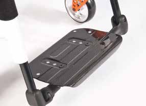
Platform Footrests
The footplates can be flipped up to make it easier to transfer to and
from the chair.
Fig. 6.3.3
The footplates can also be tilted to six different angles relative to a
level surface.
Tighten screw (1) firmly on the outer side.
By removing the clips (2) the footrest can be adjusted to three
different positions toward both the front and rear. Loosen the
adjustment screw (3) to change the horizontal position of the
footboard.
For this purpose, the footboard must be flipped up,
(Fig. 6.3.2 to Fig. 6.3.4).
When finished, make sure that all screws have been properly
tightened (see the page on torque).
A minimum interval of 25mm from the ground should always be
maintained.
Fig. 6.3.4
Krypton F 18 Rev.BWidth adjustment of footrests Fig. 6.3.5
If the footrest width needs to be adjusted, please undo the screw
ENGLISH
(1), set the desired width, by positioning 1, 2 or 3 spacers (2) from
outer to the inner side and then refit the screws, (Fig. 6.3.5).
Lightweight footrest
The footboard angle can be adjusted by loosening the screws (2).
Side protection panels can be fitted to the footboard using the
mounting holes (3). These prevent the feet slipping off accidentally,
(Fig. 6.3.6). Make sure that after any adjustment work, all screws 1 2
are tightened correctly (see the page on torque).
Fig. 6.3.6
Width adjustment
3
To adjust the width of the footboard open the screw (2). Then you
can slide in and out the tubes in the holder to adjust the width of the
footboard (Fig. 6.3.6). 3 2
Please make sure that the screws are tightened with the correct
torque.
2
Automatic folding footrest
The footrest angle can be adjusted by loosening the screws (1) and
turning the footrest. When tightening, please note the torque
measurements, (Fig.6.3.7).
Fig. 6.3.7
1
Krypton F 19 Rev.B6.4 Seating Fig. 6.4.1
Seat Sling
ENGLISH
The seat sling can be adjusted for tension by using several straps. To
adjust the tension of the seat sling all straps have to be open. By pulling
the straps the tension of the seat sling will be tightened, (Fig. 6.4.1)
NOTE: If the tension is too high, the cross brace will not be able to slide
into the saddle.
Adjusting the seat height:
Lightweight adapter
Fig. 6.4.2
To change the seat height; 3
4
• Remove the rubber bungs (3), which are located in the groove on the
rear side of the axle brackets.
• Undo the Allen screws (1) with an Allen key. Position the axle adapter
(2) on the axle bracket (4), at the desired seat height (Fig. 6.4.2). 1
• For the lowest seat height, the axle adapter should be assembled
upside down.
• To tighten the Allen screw (1) again, follow these two steps:
a) Tighten both Allen screws with a torque of 5 Nm. 2
b) Tighten both Allen screws again, with a torque of 8 Nm.
• Reinsert the rubber bungs.
Standard adapter Fig. 6.4.3 3
To change the seat height:
4
• Remove the rubber bungs (3), which are located in the groove on the
rear side of the axle brackets.
• Undo the Allen screws (1) with an Allen key. Position the axle adapter
1
(2) on the axle bracket (4), at the desired seat height (Fig. 6.4.3).
• To tighten the Allen screw (1) again, follow these two steps:
a) Tighten both Allen screws with a torque of 5 Nm.
b) Tighten both Allen screws again, with a torque of 8 Nm.
• Reinsert the rubber bungs. 2
NOTE:
• An adjustment to the castor angle may be necessary when adjusting
the rear seat height.
• If the camber adapter in the axle adapter has been moved or twisted
when adjusting the seat height, the camber and the track width must
be checked and adjusted if necessary (see the “Wheel alignment”
section).
CAUTION!
• Some of the screws that are used in manufacture have a thread lock
(blue dot on the threads) and can be used up to three times, then they
must be replaced by new screws. Alternatively, you can put Loctite™
243 threadlock on the screws and re-fit them.
• When replacing the Allen screws (1) on the axle adapter, you MUST
use Loctite™ 243 for thread locking.
Krypton F 20 Rev.BC.O.G, Setup Fig. 6.4.4
To carry out COG adjustment, there are basically 2 different options.
The adjustment can be carried out straight on the axle adapter
ENGLISH
(standard adapter only). When doing this, the crescent-shaped spacers
can be pushed from one side to the other. To make an adjustment in
larger steps, you must change the position of the axle bracket on the
frame.
NOTE:
• Changes to the centre of gravity may lead to an unstable wheelchair
which will tip over easily. In this case, anti-tip tubes are required. 1
• When determining the centre of gravity, it may be necessary to adjust
the castor angle.
Fig. 6.4.5
Changing the position of the axle brackets on the frame
Using the quick-release axles, take the wheels out of the angle
adapter.
Undo both screws (1) and remove these completely. Fit the axle stem
in the desired position on the frame, put the screws back into the
perforated plate and then re-tighten the screws. When moving the axle
stem, also move the seat saddle on the frame, (change the axle stem
and the seat saddle). Make sure that the left and right sides are fitted
in the same positions. Use the specified torque of 8 Nm to tighten the
screws (Fig. 6.4.4 to Fig. 6.4.5).
Fig. 6.4.6
Adjusting the centre of gravity with the standard axle adapter
Additional adjustments can be carried out straight on the axle adapter
(standard adapter only), and when doing this the crescent-shaped
spacers can be positioned accordingly. There are 3 positions (Fig.
1
6.4.6 to Fig. 6.4.8).
Using the quick-release axles (4), take the wheels out of the axle plug /
sleeve. Undo the Allen screws (1) with an Allen key. Remove the cover
(2) of the axle adapter and position the crescent-shaped spacers (3)
for the required centre of gravity. Put the cover back on.
To tighten the Allen screw (1) again, follow these two steps:
a) Tighten both Allen screws with a torque of 5 Nm.
b) Tighten both Allen screws again, with a torque of 8 Nm. Fig. 6.4.7
2
NOTE: If the camber adapter has been moved or twisted when adjust-
ing the seat height, the wheel alignment and camber must be checked
and adjusted if necessary (see the “Wheel alignment” section).
CAUTION!
• When replacing the Allen screws (1) on the axle adapter, you MUST
use Loctite™ 243 for thread locking.
Fig. 6.4.8
3 4
Krypton F 21 Rev.B6.5 Castors Fig. 6.5.1
Setting the Castor, Castor adapter & Castor fork
ENGLISH
If the wheelchair veers slightly to the right or left, or the castors
flutter, it may be caused by one or more of the following: +8° - 8°
• Forward and/or reverse wheel motion has not been set properly.
• The castor angle has not been adjusted properly.
• Castor and/or rear wheel tyre pressure is incorrect; the wheels
do not turn smoothly.
The optimum adjustment of the castors is required so that the
wheelchair runs in a straight line. Fig. 6.5.2
Castors should always be adjusted by an authorised dealer. The
castor plates must be re-adjusted, and the wheel receiver must be
checked every time the rear wheel position has been altered.
2
Adjusting the castor
To ensure that both forks are set parallel, simply count the teeth
visible on both sides. After setting the castor fork, the teeth will
guarantee a secure position, allowing an adjustment of 16° in 2°
3
increments (Fig. 6.5.1).
Use the flat side on the front of the castor fork to check for a right-
angled position to the ground.
1
The patented design allows the castor fork to be turned, so that it
can be reset at right-angles to the ground when the seat angle is
changed.
Setting the directional stability
Release the Allen screws (1) on the underside of the fork. You can
then remove the screws (2). You can now turn the black socket (3)
left or right.
Left – chair pulls to the left
Right – chair pulls to the right
Then re-tighten the screw (2). Please set a 90° angle from the fork
to the floor.
Then re-tighten the screw (1). (Fig. 6.5.2).
CAUTION!
Some of the screws that are used in manufacture have a thread
lock (blue dot on the threads) and can be used up to three times,
then they must be replaced by new screws. Alternatively, you can
put Loctite™ 243 threadlock on the screws and re-fit them.
Krypton F 22 Rev.B6.6 Backrest Fig. 6.6.1
To adjust the back angle, please undo the Allen screw (1) and
ENGLISH
remove it. Set to the desired position and then refit the Allen
screw in this position, and tighten to the specified torque. (Fig.
6.6.1). 1
Folding backrest
To make it easier to transport the wheelchair, the top half of the
backrest can folded down.
To do this, press both levers (1) and fold the backrest down. Fig. 6.6.2
When folding the backrest back up, please make sure that both
sides are firmly interlocked (Fig. 6.6.2 to Fig. 6.6.3).
WARNING!
• Risk of Injury: Be careful not to trap your fingers in the folding
mechanism.
Adjustable Back Sling
The adjustable back sling can be adjusted for tension by using
several straps, (Fig. 6.6.4). Fig. 6.6.3
1
Height-adjustable backrest
The backrest may be set to various back heights, in 25 mm
steps (4 adjustment ranges: 250-300 mm, 300-400 mm,
400-450 mm and 450-475 mm).
Remove the side cushions of the upholstery, and if necessary,
the belt at the back, which covers the screws.
Release the screw (1) and set the backrest to the desired
height. Then tighten the screws again (Fig. 6.6.5).
See the page on torque.
Fig. 6.6.4
CAUTION!
Please take into account the altered centre of gravity when
setting the angle of the backrest.
6.7 Headrests
The headrest (Fig. 6.7.1) can be raised and moved horizontally
both forwards and backwards.
Fig. 6.6.5
To do this, loosen the screw (1, 2 or 3).
Now you can adjust to the desired position. Tighten screws
again (see the page on torque).
1
Fig. 6.7.1
1
2
3
Krypton F 23 Rev.B6.8 Wheel Alignment Fig.
Fig.6.8.1
30
Adjusting the wheel alignment
ENGLISH
NOTE: To achieve the very best movement, the rear wheels must be
adjusted to their optimum position, which means correctly adjusting 2
the wheel alignment. To do this, measure the distance between both
wheels front and rear to ensure that they are parallel to one another.
The difference between both measurements should not exceed 5
mm. The parallel setting can be adjusted by loosening the screws (1)
and rotating the axle adapter (3).
When finished, make sure that all screws have been properly
tightened, (Fig. 6.8.1 to Fig. 6.8.2). Re-tighten the Allen screws with a
torque of 8 Nm. Fig.
Fig.6.8.2
37
2
WARNING!
Be careful, there is a risk of tipping when adjusting the centre of
gravity of the seat!
1
Adjusting the rear wheelbase width
The rear wheelbase is defined as the distance between the upper
side of the rear wheels and the backrest tubes and is factory set (125
mm). This must be increased if more space is to be created between
the tyres and the optional height-adjustable armrests. 3
To adjust the rear wheelbase:
• Move the camber adapter (3) telescopically into or out of the axle
adapter (2).
• Undo the Allen screw (1) on the rear of the axle adapter.
• Move the axle adapter (3) in or out, until the desired wheelbase is
achieved.
• To tighten the Allen screw (1) again, follow these two steps:
a) Tighten both Allen screws with a torque of 5 Nm.
b) Tighten both Allen screws again, with a torque of 8 Nm.
• Repeat the procedure on the right side of the wheelchair and set
the same gap on the left side (Fig. 6.8.1 to 6.8.2).
CAUTION!
• When adjusting the rear wheelbase, set first one wheel and then
the other.
• If the camber adapter has been moved or twisted when adjusting
the seat height, the wheel alignment must be checked and adjusted
if necessary (see the “Wheel alignment” section).
• When replacing the Allen screws (1) on the axle adapter, you
MUST use Loctite™ 243 for thread locking.
Krypton F 24 Rev.B6.9 Sideguards Fig. 6.9.1
1. Fitting 4
ENGLISH
a. push the outer armrest rails down into the receiver which is 2 5
mounted on the wheelchair frame. 3
b. the armrest will automatically lock into place. 6
2. Height adjustment 1
a. turn the release lever for height adjustment (2) to the second
stop point.
7 9
b. push the armpad up or down to reach the desired height.
c. s et the lever back to the interlocked position against the
armrest rails.
Fig. 6.9.2
d. push the armpad (4) until the rails click into place securely.
3. Remove the armrest
a. operate the lever 3 and lift the whole arm.
4. Insert armrest
a. put the armrest back in the receiver, until the arm clicks into
place.
Mounting Components For The Armrest Receiver
Adjusting the armrest receiver
To tighten or loosen the fit of the outer armrest rails in the
receiver: Fig. 6.9.3
1. Loosen the four set screws for the receiver (D) on the sides of
the receiver.
2. Leave the armrest in the receiver (E) and push the receiver
together, until the desired adjustment is achieved. 1
3. Tighten the four screws (D). (144 in-lbs, 16.3 Nm)
Position Adjustment
1. Loosen the two clamp screws (10) until the clamp is loose.
2. Push the armrest receiver to the desired position.
3. Tighten.
(Fig. 6.9.1 to 6.9.4).
Fig. 6.9.4
1. Outer armrest rails
2. Height adjustment of the release lever
3. Release lever
4. Armrest pad
5. Transfer bar
6. Sideguard
7. Receiver
8. Adjustment clamp E
9. Parts to adjust the receiver
10. Clamp screws
Krypton F 25 Rev.BSideguards (continued) Fig. 6.9.5
1 2
Side-guard with clothes protector
ENGLISH
The clothes protector prevents clothes getting dirty from spray
water, (Fig. 6.9.5).
You can set the position in relation to the rear wheel by moving
the sideguard.
To do this, remove the screws (1 and 2).
After setting to the desired position, re-tighten the screws (see
the page on torque).
WARNING!
Fig. 6.10.1
Neither the sideguards nor the armrests are to be used for lifting
or carrying the wheelchair.
6.10 Push handles 2
Height-adjustable push handles
These handles are secured with pins to prevent them from
sliding out unintentionally. By releasing the tension lever (1) the 1
height of the push handles (2) can be set individually. If the
lever is moved, listen to make sure that it clicks into place. The
push handle can easily be set to the desired position. The nut
on the tension lever determines how tightly the push handles Fig. 6.10.2
are clamped into place. If the nut is loose after adjusting the
tension lever, the push handle will also be too loose. Turn the
push handle from side to side before use to make sure that it is
clamped into place securely. After adjusting handle height,
always clamp the tension lever (1) securely into place. If the
lever is not secure, injuries could result when ascending stairs.
(Fig. 6.10.1).
CAUTION!
1
If the height-adjustable push handles are not fitted properly,
there is a risk that these will develop "play" or that they move
out of position. Please make sure that the relevant screws are
tightened correctly.
Folding push-handles
If the folding push handles are not required, they can be flipped
downwards by pushing the button (1). When they are required
again, flip the push handles up, until they click into place. (Fig.
6.10.2).
Krypton F 26 Rev.B6.11 Crutch holder Fig. 6.11.1
Crutch Holder
ENGLISH
This device permits crutches to be transported directly on
a wheelchair. It has a Velcro loop to fasten crutches or
other aids (Fig. 6.11.1).
WARNING!
Never try to use or even remove the crutches or other
aids while moving.
6.12 Anti tips
Fig. 6.12.1
WARNING!
Sunrise Medical recommends anti-tip tubes are fitted for
all chairs.
When fitting anti-tip tubes, use a torque of 7 Nm.
Anti-tip tubes prevent the wheelchair from tipping 1
backwards, providing additional safety for new users and
for users familiarising themselves with the operation of
the wheelchair.
Plug in Type
Fig. 6.12.2
Slotting the anti-tip tubes into the clamp
• Press the rear button on the adapter for the anti-tip
tube in such a way that both release pins are pulled
inwards.
• Slot the anti-tip tubes (1) into the anti-tip tube adaptor.
• Rotate the anti-tip tubes downwards, until the release
pin clicks into place in the clamp.
• Fit the second anti-tip tube in the same way.
Adjusting Anti-Tip Tubes 1
To achieve the correct ground clearance of approx. 1" to
2" (25 mm to 50 mm), the anti-tip tubes must be raised or
lowered. Swing-away Type
• Push the release lever for the anti-tip tube in such a Push down on the top of the anti-tip tube, (1), to bring
way that both release pins are pulled inwards. them into position, (Fig. 6.12.2).
• Move the inner tube upwards or downwards in the A 30 - 50 mm gap should be maintained between the anti
height-adjustment holes. tip wheels and the ground.
• Release the button. The anti-tips can also be swung into a forwards position.
• Fit the second anti-tip tube in the same way. The anti-tips must always be in the forward position when
• Both wheels should be at the same height. (Fig. negotiating large obstacles, (such as kerbs), to prevent
6.12.1). them from interfering with the manoeuvre.
DANGER!
If the anti-tip tubes are not fitted, or have been fitted
incorrectly, there is a risk of tipping over and of injury.
Krypton F 27 Rev.B6.13 Stabilizing Bar Fig. 6.13.1
Folding stabilising bar
ENGLISH
This bar is used to stabilize the backrest. To be able to
fold the wheelchair, the release lever must be pushed
inwards (Fig. 6.13.1) or released and the stabilising must
be flipped downwards.
When unfolding the wheelchair, please make sure that the
stabilising bar is locked into position.
6.14 Transit Wheels
Fig. 6.14.1
Transit Wheels
Transit wheels should be used whenever your wheelchair
would be too wide if the rear wheels were fitted (Fig.
6.14.1).
After the rear wheels have been removed with the aid of
the quick-release axles, the transit wheels can
immediately be used to continue riding, (Fig. 6.14.2).
The transit wheels are mounted so that they are approx.
30 mm above the ground when not in use. They are thus
out of the way when riding, transporting, or when tipping
to pass over obstacles.
Fig. 6.14.2
DANGER!
• Without rear wheels, your wheelchair has no wheel
locks.
• There is a risk of the chair tipping backwards.
Krypton F 28 Rev.B6.15 Pelvic Restraint Belt Fig. 6.15.2
WARNINGS!
ENGLISH
• Before using the wheelchair make sure that the pelvic
restraint belt is fitted.
• The lap belt must be checked on a daily basis to
ensure it is free from any obstruction or adverse wear.
• Always make sure that the lap strap is correctly
secured and adjusted prior to use.
DANGER!
Fig. 6.15.3
If the strap is too loose, this could cause the user of the
wheelchair to slip down and risk suffocation or serious
injury.
The pelvic restraint belt is fitted to the wheelchair as
shown in Fig. 6.15.1 to Fig. 6.15.10. The seat belt
comprises two halves. They are ftted using the existing
seat stay retaining bolt ftted through the eyelet on the
belt. The belt is routed under the rear of the side panel.
(Fig. 6.15.1).
Adjust lap belt to suit the user’s needs as follows:
Fig. 6.15.4
Adjust the belt position so buckles are in the centre of the
seat. (Fig. 6.15.2).
Feed free belt back through male buckle and slide
adjusters.
Ensure that there is no excess of belt material looped at
the female buckle end, (Fig. 6.15.3).
Feed free belt through slide adjusters and male buckle to
provide more belt length, (Fig. 6.15.6).
Fig. 6.15.5
Fig. 6.15.1 Fig. 6.15.6
Krypton F 29 Rev.BPelvic restraint belt (continued) Fig. 6.15.7
When fastened check space between the pelvic restraint
ENGLISH
belt and user. When correctly adjusted it should not be
possible to insert more than the flat of the hand between
the pelvic restraint belt and the user, (Fig. 6.15.7).
The lap belt should be fixed so that the belt sits at an
angle of 45 degrees across the user’s pelvis. The user
should be upright and be as far back as possible in the
seat when correctly adjusted. The lap belt should not
allow the user to slip down in the seat.
(Fig. 6.15.8).
Fig. 6.15.8
To fasten buckle:
Firmly push male buckle into female buckle, (Fig. 6.15.9).
To release buckle:
Press the RED button in the centre of the buckle then
pull the two halves gently apart, (Fig. 6.15.10).
NOTE: If you have any questions on the use and
operation of the pelvic restraint belt, the please contact
30°
your wheelchair dealer, carer or attendant.
WARNINGS! 75°
• The pelvic restraint belt must only be fitted or adjusted
Fig. 6.15.9
by an approved Sunrise Medical dealer / agent.
• The lap belt must be checked on a daily basis to ensure
it is adjusted correctly and free from any obstruction or
adverse wear.
• Sunrise Medical does not recommend the
transportation of a person in a vehicle with the pelvic
restraint belt as a restraint system.
See the transit brochure from Sunrise Medical
for further information on transportation.
Maintenance:
Check lap belt and securing components at regular
intervals for any sign of fraying or damage. Depending
Fig. 6.15.10
on usage, it may need to be replaced.
WARNING!
The pelvic restraint belt should be adjusted to suit the
end user as detailed above. Sunrise Medical also
recommends that the length and fit of the belt is checked
on a regular basis to reduce the risk of the end user
inadvertently re-adjusting the belt to an excessive length.
Krypton F 30 Rev.B7.0 Daily Checks 9.0 Maintenance and care
• Check the tyre pressure every 4 weeks. Check all tyres
CAUTION! for wear and damage.
ENGLISH
• Check the wheel locks approximately every 4 weeks, to
As the user you will be the first person to notice any make sure that they are working properly, and are easy
possible defects. We therefore recommend that before to use.
each use, you check the items in the following list: • Change tyres as you would an ordinary bicycle tyre.
• All of the joints that are critical to using your wheelchair
• Check for correct tyre pressures
safely are self-locking nuts. Please check every three
• Check that the wheel locks work correctly.
months to make sure that all bolts are secure (see the
• Check that all removable parts are secure, e.g.
section on torque). Safety nuts should only be used once
armrests, footrests, quick-release axle etc.
and should be replaced after use.
• Check for visible damage e.g. on the frame, backrest,
• Please use only mild household cleansers when your
seat sling and back sling, wheels, footplate etc.
wheelchair is dirty. Use only soap and water when
If there is any damage or malfunction, please contact your cleaning the seat upholstery.
authorised dealer. • If your wheelchair should ever get wet, please dry it
afterwards.
8.0 Tyres and mounting • A small amount of sewing-machine oil should be applied
to quick-release axles approximately every 8 weeks.
Depending on the frequency and type of use, we
WARNING!
recommend taking your wheelchair to your authorised
dealer every 6 months to have it inspected by trained
Always make sure that you maintain the correct tyre personnel.
pressure (min. 3.5 bar), as this can have an effect on • You should only use genuine parts approved by Sunrise
wheelchair performance. Medical. Do not use parts from other manufacturers, that
If the tyre pressure is too low, rolling resistance will have not been by authorised by Sunrise Medical.
increase, requiring more effort to move the chair forward.
Low tyre pressure also has a negative impact on CAUTION!
manoeuverability. Sand and sea water (or salt in the winter) can damage
the bearings of the front and rear wheels. Clean the
WARNING! wheelchair thoroughly after exposure.
If the tyre pressure is too high, the tyre could burst. The following parts can be removed and sent to the
manufacturer / dealer for repair:
The correct pressure for a given tyre is printed on the
surface of the tyre itself, (min. 3.5 bar). Rear wheels-Armrest-Footrest holder-Anti-Tip tubes
Tyres can be mounted the same way as an ordinary These components are available as spare parts.
bicycle tyre. For further information, please see the spare
Before installing a new inner tube, you should always parts catalogue.
make sure that the base of the rim and the interior of the
tyre are free of foreign objects.
Check the pressure after mounting or repairing a tyre. It is
critical to your safety and to the wheelchair’s performance
that regulation air pressure be maintained and that tyres
are in good condition.
Krypton F 31 Rev.B9.0 Maintenance and Care continued Wheelchair squeaks and rattles
• Check to make sure all bolts are secure; tighten if
necessary (see the section on torque)
Hygiene measures when being re-used:
ENGLISH
• Apply small amount of lubrication to spots where
Prior to the wheelchair being re-used, it must be carefully movable parts come into contact with one another
prepared.
Wheelchair begins to wobble
WARNING! • Check angle at which castors are set
• Check tyre pressure
All surfaces which come into contact with the user must • Check to see if rear wheels are adjusted differently.
be treated with a disinfection spray.
To do this, you must use a disinfectant from the DGHM 11.0 Disposal / Recycling of Materials
list, e.g. Antifect Liquid (Schülke & Mayr) for rapid
disinfection for medical products and medical devices, NOTE: If the wheelchair has been made available to you
which must be disinfected quickly. as part of a charity or medical loans scheme, then it may
Please pay attention to the manufacturer’s instructions of not belong to you. If it is no longer required, then follow
the disinfectant you are using. the instructions to return it as given by the organisation
In general, a complete disinfection cannot be guaranteed that made the wheelchair available to you.
on seams. We therefore recommend that you dispose of
seat and back slings to avoid microbacterial In the following section, there is a description of the
contamination with active agents according to § 6 materials used on the wheelchair, in view of the disposal
infection protection law. or recycling of the wheelchair and its packaging.
There may also be special local regulations in force with
10.0 Trouble shooting regard to disposal or recycling, these must be taken into
account when disposing of your wheelchair. (This can
Wheelchair pulls to one side include the cleaning or decontamination of the wheelchair
• Check tyre pressure prior to disposal).
•Check to make sure wheel turns easily (bearings, axle)
• Check the castor angle Aluminium: Castor forks, wheels, sideguards for the
• Check to make sure both castors are making proper chassis, armrest frame, footrest, push handles
contact with the ground. Carbon fibre: Frame tubes, axles, axle brackets, back
tubes.
Castors begin to wobble Steel: Fixing points, quick-release axle.
• Check the castor angle Plastic: Handles, tube stoppers, castors, footplates,
• Check to make sure all bolts are secure; tighten if armpads and tyres.
necessary (see the section on torque) Packaging: Plastic bags made of soft polyethylene,
• Check to make sure both castors are making proper cardboard.
contact with the ground. Upholstery: Polyester fabric with PVC coating and
highly-flammable foam.
Disposal or recycling should be done through a licensed
agent or authorised place of disposal. Please contact
your local waste disposal company for details relating to
the disposal of carbon fibre components. Alternatively
your wheelchair may be returned to your dealer for
disposal.
Krypton F 32 Rev.BYou can also read