Legend Belt Sander Operator's Manual - American Sanders
←
→
Page content transcription
If your browser does not render page correctly, please read the page content below

Belt Sander
   Legend
Operator’s Manual
2
READ THIS BOOK
          This book has important information for the use and safe operation of this machine. Failure to read this book prior to operating
          or attempting any service or maintenance procedure to your American Sanders machine could result in injury to you or to other
        personnel; damage to the machine or to other property could occur as well. You must have training in the operation of this machine
           before using it. If your operator(s) cannot read this manual, have it explained fully before attempting to operate this machine.
                                    All directions given in this book are as seen from the operator’s position at the rear of the machine.

       EN
  Contents
  Operator Safety Instructions.................3-6                Wiring Diagram.......................................39   Pull Pin Assembly..............................58-59
  Introduction...............................................7    Base Assembly 1...............................40-41       Belt Tensioner Assembly...................60-61
  Machine Specifications.............................7            Base Assembly 2...............................42-43       Control Carriage Assembly...............62-63
  230V Electrical Schematic.......................7               Base Assembly 3...............................44-45       Transport Dolly Assembly..................64-65
  Machine Transportation.........................8-9              Motor Assembly.................................46-47      Motor Dolly Kit Assembly..................66-67
  Machine Setup.......................................10          Capacitator Box Assembly................48-49             Stair Climber Kit Assembly................66-67
  Machine Operation............................ 11-12             Belt Guard Assembly.........................50-51
  Tool and Accessories.............................13             Dust Bag Assembly...........................50-51
  Sanding Cuts & Sandpaper....................14                  Handle Assembly Fixed.....................52-53
  Chatter Wave Prevention.......................14                Handle Assembly Adjustable.............54-55
  Sander Adjustment Procedures........15-17                       Fan Cover Assembly.........................56-57
  Routine Maintenance.............................17              Lift Handle Assembly.........................58-59
  Troubleshooting.................................18-19           Leveling Bracket Assembly...............58-59

          WARNING!
Read all safety warnings, instructions, illustrations and specifications provided with this power tool. Failure to follow all instructions listed
below may result in electric shock, fire and/or serious injury.

          WARNING!
The Products sold with this Manual contain or may contain chemicals that are known to certain governments (such as the State of
California, as identified in its Proposition 65 Regulatory Warning Law) to cause cancer, birth defects or other reproductive harm. In
certain locations (including the State of California) purchasers of these Products that place them in service at an employment job site
or a publicly accessible space are required by regulation to make certain notices, warnings or disclosures regarding the chemicals that
are or may be contained in the Products at or about such work sites. It is the purchaser’s responsibility to know the content of, and
to comply with, any laws and regulations relating to the use of these Products in such environments. The Manufacturer disclaims any
responsibility to advise purchasers of any specific requirements that may be applicable to the use of the Products in such environments.
                                                   ***This product is intended for commercial use only***

                                                                 Operator Safety Instructions

                 In this Operation Manual you will find three statements that you must read and observe to ensure safe operation of this
                 machine.

                 DANGER means: Severe bodily injury or death can occur to you or other personnel if the DANGER
                    statements found on this machine or in this Operation Manual are ignored or are not adhered to. Read
                    and observe all DANGER statements found in this Operation Manual and on your machine.
                 WARNING means: Injury can occur to you or to other personnel if the WARNING statements found on
                    your machine or in the Operation Manual are ignored or are not adhered to. Read and observe all
                    WARNING statements found in this Operation Manual and on your machine.
                 CAUTION means: Damage can occur to the machine or to other property if the CAUTION statements found
                    on your machine or in this Operation Manual are ignored or are not adhered to. Read and observe all
                    CAUTION statements found in this Operation Manual and on your machine.

                                                                                             3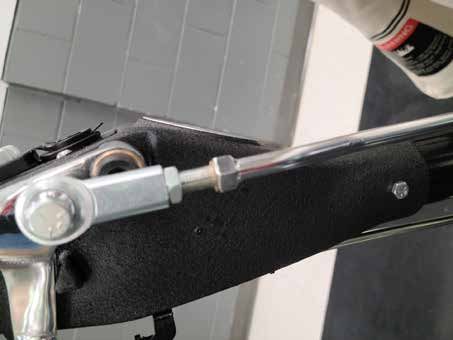
EN

        DANGER:			 Failure to read the Owner’s Manual prior to operating or servicing your American Sanders machine could result in injury to
                   you or to other personnel; damage to the machine or to other property could occur as well. You must have training in the
                   operation of this machine before using it. If you or your operator(s) cannot read English, have this manual explained fully
                   before attempting to operate this machine.

        DANGER:			 A. Sanding/finishing wood floors can create an explosive or combustible environment. Do not operate this machine around
                   solvents, thinners, alcohol, fuels, floor finishes, wood dust or any other flammable materials. Cigarette lighters, pilot lights,
                   electrical sparks and all other sources of ignition should be extinguished or avoided. Keep work area well ventilated.
                    		 B. Dust generated from sanding wood floors can spontaneously ignite or explode. Promptly dispose of any sanding dust in
                       a metal container clear of any combustibles. Do not dispose in a fire.

        DANGER:			 A. Electrocution could occur if the machine is being serviced while the machine is connected to a power source. Disconnect
                   the power supply before servicing.
                    		 B. Electrocution or fire could occur if the machine is being operated with a damaged power cord. Keep the power cord clear
                       of the pad. Always lift the cord over the machine. Do not move the machine by the power cord.
                    		 C. Shock hazard. Do not use the machine if it has been rained on or sprayed with water.

        DANGER:
                 To avoid injury keep hands, feet, and loose clothing away from all moving parts on the machine. Disconnect the power cord
                 before replacing the pad, changing the abrasive, or when servicing. Do not operate the machine unless all guards are in
                 place. Never leave the machine unattended while connected to a power source.

        WARNING:		Injury can occur if protective clothing or equipment is not used while sanding.          Always wear safety goggles, protective
                  clothing, and dust mask while sanding.

        WARNING:		This sander is not to be used on pressure treated wood. Some pressure treated woods contain arsenic and sanding
                  pressure treated wood produces hazardous dust. Inhaling hazardous dust from pressure treated wood can cause serious
                  injury or death. Sanding pressure treated wood decks or uneven surfaces can damage the sander which is not covered
                  under warranty or damage waiver.

        WARNING:		Any alterations or modifications of this machine could result in damage to the machine or injury to the operator or other
                  bystanders. Alterations or modifications not authorized by the manufacturer voids any and all warranties and liabilities.
        WARNING:		Risk of explosion. Floor sanding can result in an explosive mixture of fine dust and air. Use floor sanding machine only in a
                  well-ventilated area free from any flame or match.

        CAUTION:			 Laser Radiation - Do Not Stare Into Beam. Class 2 laser product.

                                        General Power Tool Safety Warnings
Save all warnings and instructions for future use.
    The term "power tool" in the warnings refers to your main-operated (corded) power tool or battery operated (cordless) power tool.

1) Work area safety
  a)     Keep work area clean and well lit. Clutter or dark areas invite accidents.
  b)     Do not operate power tools in explosive atmospheres, such as in the presence of flammable liquids, gases, or dust.
		       Power tools create sparks which may ignite the dust or fumes.
  c)     Keep children and bystanders away while operating a power tool. Distractions can cause you to lose control.
2) Electrical safety
  a)     Power tool plugs must match the outlet. Never modify the plug in any way. Do not use any adapter plugs with
		       earthed (grounded) power tools. Unmodified plugs and matching outlets will reduce risk of electric shock.
  b)     Avoid body contact with earthed or grounded surfaces such as pipes, radiators, ranges, and refrigerators. There is an
		       increased risk of electric shock if your body is earthed or grounded.
  c)     Do not expose power tools to rain or wet conditions. Water entering a power tool will increase the risk of electric shock.
  d)     Do not abuse the cord. Never use the cord for carrying, pulling or unplugging the power tool. Keep cord away from
		       heat, oil, sharp edges or moving parts. Damaged or entangled cords increase the risk of electric shock.
  e)     When operating a power tool outdoors, use an extension cord suitable for outdoor use. Use of cord suitable for outdoor
         use reduces the risk of electric shock.

                                                                         4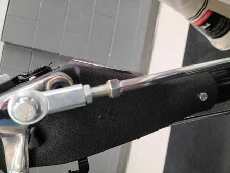
EN
  f)    If operating a power tool in a damp location is unavoidable, use a residual current device (RCD) or ground fault circuit
		      interrupter (GFCI ) protected supply. Use of a RCD or GFCI reduces the risk of electric shock.
3) Personal safety
  a)    Stay alert, watch what you are doing and use common sense when operating a power tool. Do not use a power tool
		      while you are tired or under the influence of drugs, alcohol, or medication. A moment of inattention while operating
		      power tools may result in serious personal injury.
  b)    Use personal protective equipment. Always wear eye protection. Protective equipment such as dust mask, non-skid
		      safety shoes, hard hat, or hearing protection used for appropriate conditions will reduce personal injury.
  c)    Prevent unintentional starting. Ensure switch is in off-position before connecting to power source and/or battery
		      pack, picking up, or carrying the tool. Carrying power tools with your finger on the switch or energizing power tools that
		      have the switch on invites accidents.
  d)    Remove any adjustment wrench or key before turning the power tool on. A wrench or key left attached to a rotating part
		      of the power tool may result in personal injury.
  e)    Do not overreach. Keep proper footing and balance at all times. This enables better control of the power tool in
		      unexpected situations.
  f)    Dress properly. Do not wear loose clothing or jewelry. Keep your hair, clothing and gloves away from moving parts.
		      Loose clothes, jewelry, or long hair can be caught in moving parts.
  g)    If devices are provided for the connection of dust extraction and collection facilities, ensure these are connected and
		      properly used. Use of dust collection can reduce dust related hazards. It is recommendation that the tool always be supplied
		      via a residual current device with a rated residual current of 30mA or less.
4) Power tool use and care
  a)    Do not force the power tool. Use the correct power tool for your application. The correct power tool will do the job better
		      and safer at the rate for which it was designed.
  b)    Do not use the power tool if the switch does not turn it on and off. Any power tool that cannot be controlled with the
		      switch is dangerous and must be repaired.
  c)    Disconnect the plug from the power source and/or the battery pack from the power tool before making any
		      adjustments, changing accessories or storing power tools. Such preventative safety measures reduce the risk of starting
		      the power tool accidentally.
  d)    Store idle power tools out of the reach of children and do not allow persons unfamiliar with the power tool or these
		      instructions to operate the power tools. Power tools are dangerous in the hands of untrained users.
  e)    Maintain power tools. Check for misalignment or binding of moving parts, breakage of parts and any other condition
		      that may affect the power tool's operation. If damaged, have the power tool repaired before use. Many accidents are
		      caused by poorly maintained power tools.
  f)    Keep cutting tools sharp and clean. Properly maintained cutting tools with sharp cutting edges are less likely to bind and
		      are easier to control.
  g)    Use the power tool, accessories and tool bits ect. in accordance with these instructions, taking into account the
		      working conditions and the work to be performed. Use of the power tool for operations different from those intended could
		      result in a hazardous situation.
5) Service
  a)    Have the power tool serviced by a qualified repair person using only identical replacement parts. This will ensure that
		      the safety of the power tool is maintained. If the supply cord is damaged, it must be replaced by the manufacturer, its service
		      agent or similarly qualified persons in order to avoid a hazard.
Safety Warnings For Sanding Operations
  1.    This power tool is intended to function as a sander. Read all safety warnings, instructions and specifications provided with
		      this power tool. Failure to follow all instructions listed below may result in electric shock, fire, or personal injury.
  2.    Operations such as grinding, wire brushing, polishing or cutting-off, are not recommended to be performed with this power tool.
		      Operations for which the tool was not designed may create a hazard and cause personal injury.
  3.    Do not use accessories which are not specifically designed and recommended by the tool manufacturer. Just because the
		      accessory can be attached to your power tool, it does not assure safe operation.
  4.    The rated speed of the accessory must be at least equal to the maximum speed marked on the power tool. Accessories
		      running faster than their rated speed can break and fly apart.
  5.    The outside diameter and thickness of your accessory must be within the capacity rating of your power tool. Incorrectly sized
		      accessories cannot be adequately guard or controlled.
  6.    The arbor size of wheels, flanges, backing pads or any other accessory must fit the spindle of the power tool. Accessories
		      with arbor holes that do not match the mounting hardware of the power tool will run out of balance, vibrate excessively and
		      may cause loss of control.
  7.    Do not use damaged accessory. Before each use inspect the accessory such as abrasive wheel for chips or cracks, backing
		      pad for cracks, tear or excess wear, wire brush for loose or cracked wires. If power tool or accessory is dropped, inspect
		      for damage or install an undamaged accessory. After inspecting or installing an accessory, position yourself or bystanders
		      away from the plane of the rotating accessory and run the power tool at maximum no-load speed for one minute. Damaged
        accessories will normally break apart during this time.

                                                                      5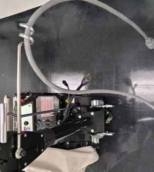
EN
  8. Wear personal protective equipment. Depending on application, use face shield, safety goggles or safety glasses. As
		    appropriate, wear dust mask, hearing protectors, gloves and workshop apron capable of stopping flying debris generated by
		    various operations. The eye protection must be capable of stopping flying debris generated by various operations. The dust
		    mask or respirator must be capable of filtering particles generated by your operations. Prolonged exposure to high intensity
		    noise may cause hearing loss.
  9. Keep bystanders a safe distance away from work area. Anyone entering the work area must wear personal protective
		    equipment. Fragments of work piece or a broken accessory mayfly away and cause injury beyond immediate area of
		operation.
  10. Hold power tool by gripping insulated surfaces (handle) only, when performing an operation where the cutting accessory may
		    contact hidden wiring or its own cord. Cutting accessory contacting a "live" wire may make exposed metal parts of the power
		    tool "live" and shock the operator.
  11. Position the cord clear of the spinning accessory. If you loose control, the cord may be cut or snagged and your arm or hand
		    may be pulled into the spinning accessory.
  12. Never lay the power tool down until the accessory has come to a complete stop. The spinning accessory may grab the
		    surface and pull the power tool out of your control.
  13. Do not run the power tool while carrying it at your side. Accidental contact with the spinning accessory could snag your
		    clothing, pulling the accessory into your body.
  14. Regularly clean the power tools air vents. The motor's fan will draw the dust inside the housing and excessive accumulation
		    may cause electrical hazards.
  15. Do not operate the power tool near flammable materials. Sparks could ignite these materials.
  16. Do not use excessively oversized sanding disc paper. Follow manufacturer's recommendations when selecting sanding paper.
		    Larger sanding paper extending beyond the sanding pad presents a laceration hazard and may cause snagging, tearing of the
		    disc or kickback.
  17. Risk of explosion. Floor sanding can result in an explosive mixture of fine dust and air. Use floor sanding machine only in a
		    well-ventilated area free from any flame or match.

Additional Rules For Safe Operation
  1.     Empty the dust bag or dust collection receiver frequently. Do not leave residue in dust bag or dust collection receiver
		       unattended. Always empty in a non-combustible metal container. Sanding wood or varnish produces dust that can self ignite
		       and cause injury or damage. Follow this precaution for storage.
  2.     Set all exposed nails. Sweep loose abrasive away from work area. Do not strike metal pipes, ect., with sanding paper.
		       Striking metal or abrasive particles with sanding paper produces sparks that could ignite the sanding dust which can cause
		       injury or damage.
  3.     Do not operate a partially assembled power tool. Keep all adjustments within manufacturer's specifications. Keep all fasteners
		       tight. Operating a partially assembled power tool could result in injury to the operator or bystander and could cause damage to
		       the equipment or surroundings.
  4.     Do not attempt to change the sanding paper while the power tool is running. The sanding drum can snag clothing and cause
		       injury to limbs, and moving sanding paper can cause abrasions.
  5.     The power tool should only be used on an electrical system (mains) that is rated for the electrical requirements of the power
		       tool as shown on the nameplate. Use only on an earthing (grounded) system. Do not service the power tool if it is energized
		       or connected to an electrical circuit. Improper use could cause fire or electric shock.

                                                                      6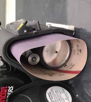
EN
                                                                  Introduction
 The American Legend can be used on a variety of wood types. It is an ideal tool for wood flooring maintenance and restoration
 work. It is not intended to be used on pressure treated wood, OSB, plywood or any other flooring type.
                                                      Machine Specifications
           Part #                  07236A / 07236B / 07236C                    07241A / 07241B / 07241C
Model                           Legend                                       Legend
Electrical Requirements         230~, 60Hz / 15.7 A, 3.7 kW                  230~, 50Hz / 16,0 A, 3,0 kW
Sound Emission (Lpm)*           86.0 dB(A)                                   86.0 dB(A)
Vibration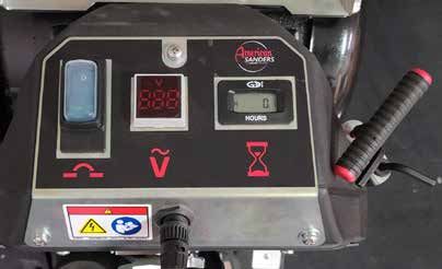
EN
                                                          Machine Transportation

  WARNING:               The machine is heavy. Remove the motor from the                     Circuit Breaker      AC Volt Meter       Hour Meter
		                       machine before transporting. Get help loading the
		                       machine and motor. Use proper lifting techniques.

Transporting the Machine - Using the Dolly Cart
  CAUTION:               When deploying the dolly, the drum will contact the
		                       floor or ground over which the machine is resting.
		                       Care should be taken to avoid surfaces which might
		                       damage or contaminate the drum.

  CAUTION:               While transporting using the dolly, abrupt changes in                                                        Handle Pigtail
		                       the direction of travel or the surface over which the                                                        C
		                       machine is being transported could cause the machine
		                       to tip over. Also, the machine is more likely to tip over
		                       when transporting across inclined surfaces.
                                                                                                                           Figure 1
Attaching and deploying the dolly:
1. Make sure the power cable is disconnected from the machine.
2. Attach the dolly to the rear of the machine by inserting the connection rod on the dolly into the two receiving clips on the back of the machine. (see Figure 2)
3. With the dolly attached to the machine as described above, tip the machine by lifting up on the operator's handle to raise the rear of the machine off the floor/
    ground until the dolly swings under the machine. (See figure 3)
4. Using your foot, push the dolly into the retaining clips on the bottom of the machine.
5. Allow the machine to tip back and rest on the dolly wheels. (See figure 4)

Removing/Storing the dolly
The dolly can be stored on the machine in the “UP” position or it can be removed and stored separately.
1. Lift up on the operator's handle to tip the machine forward.
2. Pull the dolly out from under the machine. (See figure 5)
3. Rotate the dolly up toward the operator's handle. Push the dolly into the retaining clips on the back of the machine.
4. Lower the machine back to the floor.
5. To remove the dolly, push up on the two clips holding the connection rod and remove the dolly from the machine. (See figure 6)

                      Figure 2                                                 Figure 3                                                  Figure 4

                      Figure 5                                                 Figure 6                                                  Figure 7

                                                                                  8
EN
Figure 8 Figure 9 Figure 10
Transporting the Machine - Two Person
NOTE: This is accomplished by removing the motor from the
chassis and transporting the motor and chassis separately.
To transport the machine, follow this procedure:
1. Make sure the power cable is disconnected from the machine.
2. Loosen the belt guard door retention bolt and open the belt guard door.
(See figure 7)
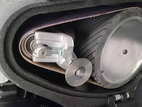
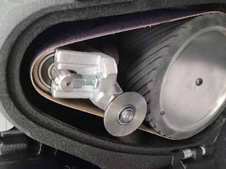
3. Release the tension on the drive belts using the quick release lever.
(See figure 8)
4. Remove the drive belts from the machine.
5. Disconnect the handle pigtail from the motor. (see figure 9) Figure 11
6. Pull the spring loaded pull pins on each side of the motor and turn ¼
turn until they fall into indentions. (See figure 10)
7. If not already installed, install the motor lift handle by fitting the handle
key hole slots to the motor and sliding until latched. (See figure 11)
8. Straddle the motor and grasp the motor lift handle. Using your legs, lift
the motor off the chassis and take it to the work site.
9. Remove the motor lift handle from the motor by lifting the release lever
and sliding the handle off the motor.
10. Install the motor lift handle to the front of the chassis by fitting the
handle key hole slots to the chassis and sliding until latched.
11. Person number 1 lifts with the operator's handle and person number 2
lifts with the handle on the front of the chassis.(See figure 12)
To replace motor after transport. Figure 12
1. Remove the motor lift handle from the chassis and install on the motor.
2. Open the belt guard door.
3. Place the motor assembly on the chassis and pull the spring loaded
pull pins and rotate them back ¼ turn to the seated position Note:
Make sure the motor pigtail is not under the motor. (see figure 13)
4. Install the drive belts and tighten by rotating the quick release lever
Note: there is a belt orientation diagram on the side of the motor for
reference.
5 . Check the tension on the belts, close the door and tighten the belt
guard retention bolt.
CAUTION: Premature bearing failure can occur if the
fan belt is set too tight. The fan belt should
deflect ½” at the center of the span with 5 lbs.
of pressure.
NOTE: It may be necessary to adjust the fan belt independently
during this procedure or during replacement. The idler pulley is factory
adjusted. Refer to sander adjustment procedures.
Figure 13
9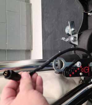
EN
                                                              Machine Setup
    To set-up your machine, follow this procedure:
    1. Familiarize yourself with the machine and read all danger,
       warning and caution statements. Make sure all operators of this
       machine have read this Operator’s Manual. If they cannot read
       this manual, have the manual explained fully before allowing
       anyone to operate the sander.
    2. Locate the electrical source. The receptacle should be
       compatible with the plug. The receptacle must be grounded and
       must be fused (see nameplate for electrical requirements) to
       avoid an electrical hazard.
    3. Make sure the ring on the dust bag is flipped open. (See figure 14)
                                                                                Figure 15
    4. Slide the opening onto the dust tube until it touches the flange,
       orienting the pin into the locating hole on the dust tube flange.
       (See figure 15)
  5. Flip the ring around tab in the dust tube to lock into place.
		 (See figure 16)
  6. Wind the power cord through the cable arm. (see figure 17)
     Keep the power cord out of the path of the machine.
		 DO NOT connect the power cord to the motor at this time.
  7. Open the sanding belt access door by lifting the quick release
		 lever. The door will spring open. (See figure 18)
  8. Rotate the sanding belt release lever forward (See figure 19)
		CAUTION: Damage to the sanding drum will occur if the                         Figure 16
			machine is operated without a sanding belt.
  9. Install a new sanding belt by sliding the belt over the tension
		 roller and drum. (See figure 20)
  10. Rotate the sanding belt release lever backward to tighten the
		 sanding belt.
		CAUTION: Do not force the release lever. Doing so can
		 damage the tracking mechanism and cause the sanding belt
		 to mis-track.
    11. Connect the handle pigtail to the motor. (See figure 9)
  12. Connect the power cord to the motor pigtail. The connection must
                                                                                 Figure 17
		 be twisted clockwise to lock. (See figure 21)
  NOTE: Ensure the breaker on the control panel is in the ON position.
  13.   Turn the control switch (See figure 22) on momentarily while
		      observing the belt tracking. Follow the procedures outlined in the
		      “Sander Adjustment Procedures” section on page 14 to correct
		      the belt tracking. There is also a label on the inside of the access
		      door that outlines the belt adjustment.
    14. Close the access door.                                                  Figure 17

                                  Figure 14                                     Figure 18

                                                                           10
EN
Operating Instructions
DANGER: Sanding/finishing wood floors can create an
environment that can be explosive. Cigarette lighters,
pilot lights and any other source of ignition can create
an explosion when active during a sanding session.
All sources of ignition should be extinguished or
removed entirely if possible from the work area.
DANGER: Work areas that are poorly ventilated can create an
explosive environment when certain combustible
materials are in the atmosphere, i.e., solvents,
thinners, alcohol, fuels, certain finishes, wood dust and
Figure 19
other combustible materials. Floor sanding machines
can cause flammable material and vapors to ignite.
Read the manufacturer’s label on all chemicals used
to determine combustibility. Keep the work area well
ventilated.
DANGER: Sanding dust can self ignite and cause an injury or
damage. Remove the contents of the dust bag each
time you finish using the machine. Always dispose of
the dust in a metal container located outside of the
building. Never leave a dust bag unattended with
sanding dust in it. Empty the contents frequently.
Do not empty the contents of the dust bag into a fire.
DANGER: Hitting a nail while sanding can cause sparks and
create an explosion or fire. Always use a hammer and
punch to countersink all nails before sanding floors.
CAUTION: Machine will pull itself forward. Make sure to have
firm control of the operator's handle when lowering the
drum to the floor.
CAUTION: Keep people out from in front of machine while in use. Figure 20
Serious injury could occur.
To operate the machine follow this procedure:
1. Before sanding, decide on best approach for sanding desired area.
If the floor is uneven, it may be necessary to sand diagonally to the
direction that the floor is laid. This will help “pull” or stretch low and
high spots in the floor over a greater area, producing a flatter surface.
Preliminary cuts should be performed at angles approximately 15°
to the direction of the wood grain. Cut direction should change on
successive cuts with the final cut performed in the direction of the wood
grain. This will minimize the tendency of waves to form and provide the Figure 21
most even floor surface.
When sanding the area, work in such a way so that you are moving
away from where the cord set enters the room. This will help to avoid
entanglement with the cord set and eliminate the need to move the cord
set out of the way so frequently.
Work the area in a way that avoids interruption or termination points (an
end of pass). Make long continuous passes.
2. Swing cable arm to side of machine opposite the direction you intend
to work. Rotate elbow on dust pipe until dust bag rests on motor. This
will maintain balance and sanding pressure as the dust bag fills. The
machine should be operated with the dust bag in this position whenever
possible. Figure 22
11EN
Operating Instructions
3. If the operating belt (American Sanders PN 53560A) is used,
proceed as follows:
a. Position the operating belt around waist.
b. Cross the straps at the waist. (See figure 23)
c. Slide the belt loop end over the handle on the control lever
side. Adjust the length as needed.
d. Wrap the remaining strap around the opposite side of the
handle, and hold it in place with your hand.
WARNING: Serious operator injury could occur if the operator
has tied or strapped the loose end of the operator’s belt strap to the
machine. Always wrap the strap so that you can let go and get away Figure 24
quickly in case of bag fire or explosion.
4. Activate the control switch.
CAUTION: To prevent damage to the floor, make sure the
machine is in motion when the sanding drum is engaged with the floor.
5. Feather-cut in by easing the sanding drum down onto the surface
with the control lever while the sander is in motion.
6. When sanding drum is fully engaged with the surface, gradually
adjust your pace for adequate finish removal. Keep sander in motion
while the sanding drum is engaged with the surface or drum marks
will occur. Figure 25
7. Move the machine in the direction of the grain in the wood whenever it is
possible. Sand the surface at a constant pace.
8. Gradually feather-cut out at the termination point by easing the
sanding drum up with the feathering handle. (See figure 24)
9. Repeat technique described in steps 5, 6, 7, and 8 and sand back
down pass just made. When completed, begin a new pass by
overlapping previous pass half the width of the abrasive. Stagger
termination points to prevent a distinct ridge and a better blend
when edging.
10 Empty contents of the dust bag into a metal container located
outside the building. Dust bag should be emptied whenever full, as Figure 26
indicated on bag.
WARNING: Do not overfill dust bag or serious fire may result.
Never leave a dust bag containing dust unattended. Sanding dust
can self ignite and cause a fire or explosion. Use only genuine Amer-
ican Sanders replacement bags.
CAUTION: An overfilled dust bag may effect machine balance
and performance. Do not handle or disturb dust bag and elbow
while sanding or damage to the floor may occur.
Figure 27
Figure 23 Figure 28
12EN
Tool and Accessories
Tools
1. Wrench-Paper Clamp Open End 7/16 & 9/16 (59810A)
2. Wrench – Open End 15/16 & 3/4 (60498A)
3. Hex Wrench “T” Handle 3/32 (51273A)
4. Hex Wrench right angle 7/32 (51274A)
5. Hex Wrench right angle 3/16 (AS036600)
Accessories - Stair climber
1. Remove the motor from the chassis. See “Transporting the
Machine” (p.9).
2. Make sure transport dolly is in the “UP” stored position or removed.
See “Attaching and deploying transport dolly” (p.8). Figure 30
3. Align key slot holes on the stair climber to the front attachment
points on the chassis and slide until latched. Note orientation in
figure. (See figure 25)
4. Place foot in front of front wheel of stair climber.
5. Using the operator's handle of the machine, lift and rotate the
machine over the stair climber. (See figures 26 and 27)
CAUTION: Use proper lifting techniques and keep firm grip
of chassis.
6. Transport machine to stairs, curb, or other raised area.
7. Pull chassis up stairs using the operator's handle.
Note: Use proper lifting techniques. (See figure 28) Figure 31
To lower the chassis from the stair sander:
1. Place foot in front of front wheel of stair climber. (See figure 29)
2. Rotate chassis slowly back over onto its wheels. (See figure 30)
Accessories - Motor Dolly
The motor can be transported with the stair climber in combination with the
motor dolly.
1. Remove motor from chassis. See “Transporting the Machine” (p.9).
2. With motor on the ground, rotate motor until wooden motor handle
is touching the ground. (See figure 31)
3. Attach motor dolly to the stair climber by lining up the keyhole slots
on the motor dolly to the connection points on the stair climber and Figure 32
slide until latched. (See figure 32)
4. Slide the motor dolly lip under the motor mount bar while aligning
the edges of the motor dolly to the edges of the motor mount bar.
(See figure 33)
5. Pull back on the handle of the motor dolly until the wheels are on
the floor and transport the motor where needed.
CAUTION: Use proper lifting techniques and keep firm grip of
motor dolly handle.
6. Pull motor up stairs using the motor dolly handle. Note: Use proper
lifting techniques. (See figure 34)
Figure 33
Figure 29 Figure 34
13EN
Sanding Cuts & Sandpaper
Initial Cut
The purpose of the initial cut is to remove old finish and gross imperfections on the floor surface. The sanding equipment should be adjusted to
heavy sanding pressure setting and a coarse abrasive belt should be used. If the surface is severely damaged by deep scratches, preexisting dwell
marks, uneven planks, etc., it may be necessary to sand across or diagonally to the grain to restore evenness to the surface. If these conditions are
not present, the initial cut should be done in the direction of the grain.
If glazing, loading, or burning takes place immediately into an initial cut, select a coarser abrasive. If this should occur during an initial cut, the
abrasive has dulled and must be replaced.
Final Cuts
The purpose of a finishing cut is to remove the scratches produced during the initial cut. Use a fine (60 - 80 grit) grain abrasive and a reduced
ESPAÑOL
sanding pressure setting. ES
If the surface remains rough after a finishing cut, it may be necessary to use an even finer grain of abrasive (80 - 100 grit). Care should be taken in
selecting the grit sizeCómo
of the abrasive. A very finede
evitar marcas grain will close the pores on a wood floor making admission of a stain difficult.
If glazing or burning vibraciones y ondulaciones
should occur immediately into a finishing cut, reduce the sanding pressure. If it should occur during a finishing cut, the abrasive
has dulled and must be replaced.
Las máquinas de Clarke Sanders están diseñadas y fabricadas con las
tolerancias más estrictas. Sin embargo, después de un corte de acabado, es
Chatter Wave Prevention
posible ver marcas de vibraciones y ondulaciones.
La forma más segura para eliminar las marcas de vibraciones es realizar el
American Sanders floor sanders
acabado are designed
del piso and manufactured
con una lijadora to thetal
giratoria horizontal, most rigid
como la lijadora 16
tolerances. However,deafter a finishing cut it is possible to see “chatter” or “waves”.
Clarke.
For flattest results, finish
Parathe floor with
minimizar a rotating
las marcas de horizontal
vibracionessander,
cuando such as the
se utiliza unaAmerican
lijadora de
Sanders Epoch HD. correa o tambor, deberá seguir los siguientes pasos:
To minimize chatter when using a belt or drum sander the following steps should be taken:
1. MARCAS DE TAMBOR...se producen cuando el operador baja el
1. DRUM MARKS...aretamborcausedal by
pisothe
sinoperator lowering
desplazarse hacia the drum Estas
delante. to themarcas
floor without
deben
forward traverse. These markscortando
eliminarse should enbe un
removed
ángulo by cutting
de 45 at arespecto
grados 45 degree
a la angle
marca.to
the mark. Cutting atCortar
the mark
en elwhile
lugarmaintaining
de la marca the samesepath
mientras will only
mantiene increase
el mismo the
recor-
mark depth and width.
rido(See figure incrementará
solamente 35) la profundidad y la anchura de la marca.
2. UNEVEN WALKING(Consulte la figura
PACE...can 14)lengthy “waves”. The machine cuts more
leave
material during the slower pace. Pay particular attention to a steady even pace.
2. ESPACIO DE RECORRIDO IRREGULAR...puede dejar “ondulaciones”
3. EXCESSIVE LIGHTprolongadas.
CUTS...may reveal high spots
La máquina on the
corta más paperdurante
material drum and cause
el ritmo más
chatter. Take a heavier
lento.cutPreste
and increase
especial the pace.para mantener un ritmo constante y
atención Figure 35
uniforme. Figura 14 the drum is clean and
4. DEBRIS... lodged between the paper and the drum will leave chatter. On a belt sander, debris may be adhered to the drum. Insure
free of debris before placing the paper.
3. CORTES LIGEROS EXCESIVOS...pueden revelar grandes manchas
en la rueda
5. ABRASIVE QUALITY...may de papel/contacto
vary. Belt seams cany causar marcas
be thicker on de
lowvibraciones. Tome
quality paper and cause chatter. Use only American Sanders specified sandpaper.
un corte más pesado e incremente el ritmo.
Store abrasive according to manufacturer’s recommendation.
4. LOS RESIDUOS...alojados entre el papel y el tambor dejarán marcas
PROPER CARE OF YOUR de
MACHINE CANEnMINIMIZE
vibraciones. CHATTER
una lijadora de correa,AND WAVES.pueden
los residuos
4. LAS RUEDAS DE CONTACTO (TAMBORES)...pueden
1. POLY V-BELTS...canadherirse al tambor. Asegúrese de que el tambor esté limpio y libre de
cause vibration and chatter if they are of low quality. Use only belts specified
noby American
presentar Sanders.
redondez y causar marcas de vibraciones.
residuos antes de colocar el papel.
2. TRUCK AND CASTER WHEELS...with flat spots, out-of-roundness, or debris adhered to their surface Póngase canen contacto
cause con su
“waves” or distribuidor de Clarke
a “chatter effect”. para clean
Always
and inspect all wheels
5. LAbefore
CALIDAD starting to sand and beforevariar.
DEL ABRASIVO...puede the finish
Las cut. Replace
costuras solicitar asistencia a la hora de corregir o cambiar el
de la or true the wheels if found to be out-of-round. Never allow the sander to
stand on hard surfaces for pueden
correa lengthyser
periods of time. en papel de poca calidad y causar
más gruesas tambor.
marcas de vibraciones. Utilice únicamente papel de lija especificado
3. DUST PICK-UP SHOES...may
por Clarke. need to beeladjusted
Almacene abrasivo for differentcon
de acuerdo materials that are to be sanded.
las recomenda- 5. An
LOSimproperly adjustedel shoe
COJINETES...en motor,will leave trailing
el tambor debris that will
o el sistema
be run over by the wheels and cause “random
ciones del fabricante. waves”. de ventilación pueden desgastarse y producir marcas de
vibraciones.
4. CONTACT WHEELS (DRUMS)...may be out-of-round and cause “chatter”. Contact your American Sanders dealer for assistance to true or replace the drum.
EL CUIDADO ADECUADO DE SU MÁQUINA PUEDE MINIMIZAR MARCAS
5. Bearings...in DE
the VIBRACIONES
motor, drum, orYfan 6. cause
system may become worn and induce vibration which could
ONDULACIONES. LAS POLEAS...que
“chatter”. estén dañadas o desgastadas en
exceso pueden producir marcas de vibraciones. Póngase
6. Upper roller...If worn or damaged, can cause chatter marks. Check upper roller before each job. en contacto con un distribuidor de Clarke para obtener
1. LAS CORREAS EN V...pueden causar marcas de vibraciones si son
7. Worn or dull abrasive...Can
de poca cause
calidad.chatter
Utilicemarks. Change
únicamente abrasive
correas belt regularly.
especificadas por Clarke. asistencia.
NOTE: American Sanders is not responsible for rework of floors that are unacceptable to the customer.
2. LAS RUEDAS DE CAMIÓN Y ROLDANAS PIVOTANTES...con 7. ItLaisTENSIÓN
your responsibility
DEL PAPEL to DE
insure your equipment
LIJA...debe is in proper
liberarse siem-
operating order, andpartes
that you use the right machine for the job.
planas, sin redondez o con residuos adheridos a su superficie pre cuando la máquina permanezca apagada durante
pueden causar efectos vibratorios o ondulatorios. Limpie e inspec- 10 minutos o un período más prolongado para evitar la
cione siempre todas las ruedas antes de comenzar a lijar y antes del compresión del tambor.
corte de acabado. Reemplace o corrija las ruedas en caso de que
no presenten redondez. Nunca permita que la lijadora repose sobre NOTA: Clarke no es responsable del trabajo de
superficies duras durante períodos de tiempo prolongados. reparación de los pisos que sean inaceptables al
14 cliente. Es su responsabilidad asegurarse de que su
3. LAS ZAPATAS DE RECOLECCIÓN DE POLVO...pueden necesitar un equipo esté en buenas condiciones operativas y de
que usted utiliza la máquina adecuada para realizarEN
Sander Adjustment Procedures
DANGER: Electrocution could occur if maintenance and
repairs are performed on a unit that is not properly dis
connected from the power source. Disconnect the power
supply before attempting any maintenance or service.
DANGER: Moving parts of this machine can cause serious
injury and/or damage. Keep hands, feet and loose
clothing away from all moving parts of the sander.
The following information provides details on how to adjust different
Figure 36
features/controls of the sander.
Dust Shoe
To adjust the dust shoe follow this procedure:
1. Disconnect machine from power supply.
2. Loosen the three screws fastening the dust shoe to chassis.
3. Adjust the dust shoe down to reduce clearance.
4. Adjust the dust shoe up the increase clearance.
5. Align the dust shoe to the chassis and tighten screws.
(See figure 36)
Figure 37A
Laser Adjustment
1. Plug machine into power cord.
2. Remove protective cap from end of laser.
Note: Ensure the circuit breaker is in the ON position.
CAUTION: Laser Radiation- Do Not Stare into Beam.
Class 2 laser product.
3. Loosen the set screw on the side of the laser holder.
(See figure 37A)
Note: Make sure the floor is level before adjusting laser line.
4. Line up the laser with a seam in the floor. (See figure 37B)
Figure 37B
5. Using a combination square placed against the wall, twist the
laser until it lines up with the edge of the square. (See figure 37C)
6. Tighten the set screw on the side of the laser holder.
Sanding Pressure
There are 5 pressure settings (1-5). Level 1 is the lowest pressure with
level 5 being the highest pressure. To change the setting, raise or lower
the lever and place in desired position. (See figure 38)
Figure 37C
Figure 38
15EN
Sander Adjustment Procedures
Leveling the Drum
CAUTION: The belt tracking maybe adversely effected if
machine is operated unleveled.
The machine is leveled at the factory set and no adjustments should be
necessary. After any maintenance is performed to the carriage system,
the pointer on the leveling bracket must be returned to original mark.
(See figure 39).
If it is necessary to reset level after replacing wheels follow this
procedure: Figure 39
1. Lower the drum to the floor.
2. Drive the adjusting screw in, to sand heavier on the left (the drive
belt side). Back the adjusting screw out, to sand heavier on the A
right (the side opposite the drive belts). Test the setting on an even
surface. Make further adjustments if necessary.
A
3. Mark new pointer location on main frame.
Belt Tracking
NOTE: The sanding belt should run evenly on the face of the drum.
For this, the outer edge of the sanding belt must be .09 inches (2mm) Figure 40A
out from the end of the drum. This provides optimum transition between
“passes”.
WARNING: Injury to the operator could occur if any machine B
adjustments are made while the motor is running. Do not
attempt to make any adjustments while the machine is B
plugged in or running.
To adjust the belt tracking follow this procedure:
1. Locate the belt tracking adjuster screw. (See figure 40A)
2. Hold the belt tracking adjuster screw and loosen the locknut. Figure 40B
(See figure 40B).
3. Rotate the tracking adjuster screw counterclockwise to move
the belt in.
4. Rotate the tracking adjuster screw clockwise to move the belt out.
5. Test adjustment and tighten the locknut.
Operating Control
A
To increase the travel or extend the reach on the grip control, follow this
procedure: A
1. Loosen the locknut on the control rod. (See figure 41A)
Figure 41A B
2. Screw the control rod adjuster (See figure 41B) “In” until the
desired reach is found. B
3. Tighten the locknut.
To decrease the travel or reduce the reach on the grip control, follow this
procedure:
1. Loosen the locknut on the control rod. (See figure 41A)
2. Screw the control rod adjuster “out” until desired reach is found.
3. Tighten the locknut.
Figure 41B
16EN
Handle Height Adjustment
1. Remove power.
2. Lower the control lever.
3. Depress the button on the link rod. Twist outer tube to disengage.
(See figure 42)
4. Loosen the handle lever on the front of the handle tube. (See figure 43)
5. Pull the pin on the side of the handle tube and position operator
handle as desired. (See figure 44)
Note: The handle has 4 height positions. The pull pin should fall into
one of those positions.
6. Tighten the handle lever on the front of the handle tube.
7. Raise the control lever until the link rod snaps into place.
Then twist the outer tube to lock into place. Figure 43
Figure 42 Figure 44
Routine Maintenance
The following items need to be periodically inspected and maintained to keep your sander in good working condition.
Sanding Chamber
Periodically blow out the sanding chamber to prevent large accumulations of debris which could interfere with the performance of the tension
roller. NOTE: The tension lever should be in the run/tight abrasive position to blow out.
Wheels
Periodically remove the debris from the truck and caster wheels. Debris can cause waves on a sanded surface.
Upper Roller
Remove the upper roller and blow dust and debris out of upper roller assembly regularly. If dust and debris get compacted in assembly, paper
tracking issues will occur.
Dust Bag
Remove the dust bag from the machine, unzip, empty and shake thoroughly to remove sanding dust from the bag. Turn the dust bag inside
out and hand wash in cold water and let air dry to prevent pore blockage and loss of dust recovery.
Drive Belt
To increase belt tension, open belt guard door and release tension using quick release lever. (See figure 8) Turn the adjustment screw “OUT”
(See figure 45) one quarter turn. Restore tension using quick release lever and check adjustment. Repeat this process if necessary. To lower
tension, the adjustment screw is turned “IN”.
Bearings
Periodically check the bearings for wear or damage according to the
following schedule:
Guide rollers after 1st 200 hrs. Fan shaft after 1st 500 hrs.
Idler pulley after 1st 200 hrs. Tension roller after 1st 500 hrs.
Arbor shaft after 1st 500 hrs.
Motor shaft after 1st 500 hrs.
Rollers
Periodically check the guide rollers and the tension roller for wear.
Figure 45
17EN
Troubleshooting
Problem Cause Action
Drive belts slip. Insufficient tension. Tension drive belt as described in
(Squeaking or squealing sound) adjustment procedures.
Worn belts. Replace belts.
Squealing, growling or grinding noise Damaged and/or worn bearing. Remove drive belts, rotate arbor motor, fan,
coming from machine. shafts and idler pulley to locate dragging or
rough bearing. Contact an authorized dealer.
Dust pickup is poor. Dust bag is full. Empty contents of bag.
Dust bag is dirty. Shake debris from bag and wash.
Dust shoe is improperly adjusted. Readjust dust shoe.
Dust chute is obstructed. Remove fan cover and clear throat.
Motor will not start. Defective motor starter. Contact an authorized dealer.
Defective start capacitor. Contact an authorized dealer.
Defective electronic start switch. Contact an authorized dealer.
Low voltage from poor connection. Contact an authorized dealer.
Defective motor. Contact an authorized dealer.
No power. Check electrical source and connections.
Tripped circuit breaker. Reset
Motor pigtail disconnected. Connect motor pigtail to motor (See figure X)
Control switch defective Replace Control switch
Motor runs sluggishly. Low voltage from excessive footage, Locate power source nearer to work site.
undersized extension cord, or poor Decrease sanding pressure.
connection.
Defective run capacitor. Contact an authorized dealer.
Defective motor. Contact an authorized dealer.
Operate machine between 208-240 VAC.
Motor circuit breaker trips/ Excessive load. Contact an authorized dealer.
repeatedly trips. Defective electronic start switch. Contact an authorized dealer.
Defective motor starter. Contact an authorized dealer.
Low voltage from poor connection. Contact an authorized dealer.
Defective motor. Contact an authorized dealer.
Defective capacitor. Contact an authorized dealer.
Uneven cuts. Leveling out of adjustment. Readjust leveling.
Abrasive belt tracking. Adjust belt to track towards the edge of drum
with deepest cut.
Burning or glazing. Dull abrasive. Replace abrasive.
Excessive sanding pressure. Decrease sanding pressure setting.
(Fig. #16, page 15).
Too fine of an abrasive belt. Use coarser abrasive.
18EN
Troubleshooting
Problem Cause Action
Slow cutting. Dull abrasive. Replace abrasive.
Too fine of an abrasive belt. Use a coarser abrasive belt.
Insufficient sanding pressure. Increase sanding pressure setting.
(Fig. #16, page 15).
Waves on sanded surface. Debris on wheels. Remove and clean wheels.
Flat spot on tire(s). Replace tires.
Chatter marks on sanded surface. See Chatter Wave Prevention, See Chatter Wave Prevention,
(Close evenly spaced ripples) page 14. page 14.
Difficult to actuate tension release lever. Debris interferes with mechanism. Blow out sanding chamber. Remove and
Worn sleeve bearing. disassemble mechanism. Clean out.
Galled linkages. Replace.
Lubricate with WD-40.
Abrasive belt hunts (seeks). Worn sleeve bearing. Check for excessive play, replace.
High edges on drum. Contact an authorized dealer or replace
the drum.
Abrasive belt will not track. Extreme difference in side-to-side Replace abrasive belt.
length of belt.
High edge on drum. Check several different abrasive belts.
Contact an authorized dealer or replace
the drum.
Abrasive belt tears along its length. Debris built-up on (top) tension roller. Clean tension roller.
Laser does not work. Defective DC power supply. Replace DC power supply.
Loose connection. Check wiring connections.
Defective laser. Replace laser.
USB charger does not work. Defective DC power supply. Replace DC power supply.
Loose connection. Check wiring connections.
Defective USB charger. Replace USB charger.
Volt Meter does not work. Defective volt meter. Check wiring connections.
Loose connection. Replace volt meter.
Front Lights not working. Defective DC power supply. Replace DC power supply.
Loose connection. Check wiring connections.
Defective LED bulb. Replace LED light bulbs.
1920
LISEZ CE MANUEL
         Ce manuel contient des informations importantes relatives à l’utilisation et au fonctionnement sûr de cette machine. Si
        vous ne lisez pas ce manuel avant de faire fonctionner ou d'effectuer toute procédure d’entretien ou de maintenance à
       votre machine American Sanders, vous pourriez subir des blessures ou causer des blessures à autrui ; des dommages à
       la machine ou à d'autres biens pourraient également se produire. Vous devrez être formé à l’utilisation de cette machine
        avant de l’utiliser. Si vos opérateurs ne peuvent pas lire ce manuel, faites le leur expliquer en entier avant de tenter de
                                                     faire fonctionner cette machine.

                        Toutes les consignes contenues dans le manuel ont été effectuées du point de vue de l’opérateur à l’arrière de la machine.

       EN
  Contenu
  Consignes de sécurité de l'opérateur..... 22-24                     Maintenance périodique...............................35         Ensemble de poignée réglable............... 54-55
  Introduction...................................................25   Dépannage.............................................. 36-37   Ensemble couvercle de ventilateur........ 56-57
  Caractéristiques de la machine....................25                Schéma de câblage......................................39       Ensemble poignée de levage................ 58-59
  230 V Schéma électrique............................ 25              Ensemble de base 1............................... 40-41         Ensemble support de mise à niveau...... 58-59
  Transport de la machine......................... 26-27              Ensemble de base 2............................... 42-43         Ensemble goupille................................... 58-59
  Installation de la machine.............................28           Ensemble de base 3............................... 44-45         Ensemble tendeur de courroie............... 60-61
  Utilisation de la machine......................... 29-30            Ensemble moteur.................................... 46-47       Ensemble chariot de commande............ 62-63
  Outils et accessoires.................................... 31        Ensemble boîtier du condensateur......... 48-49                 Ensemble chariot de transport............... 64-65
  Coupes de ponçage et papier de verre.......32                       Ensemble garde-courroie....................... 50-51            Ensemble kit chariot motorisé................ 66-67
  Prévention des vibrations............................ 32            Ensemble sac à poussière..................... 50-51             Ensemble kit monteur d’escalier............ 66-67
  Procédures de réglage de la ponceuse... 33-35                       Ensemble de poignée fixe...................... 52-53

          MISE EN GARDE !
Lire tous les avertissements de sécurité, les instructions, les illustrations et les spécifications fournis avec cet outil électrique. Le non-respect des
instructions ci-dessous peut entraîner un choc électrique, un incendie et/ou des blessures graves.

          MISE EN GARDE !
Les produits vendus avec ce manuel contiennent ou peuvent contenir des produits chimiques connus de certains gouvernements (comme l'État de
Californie, tel qu'il est mentionné dans la loi d'alerte réglementaire de la Proposition 65) pour pouvant causer le cancer, des malformations congénitales
ou d'autres dommages à la reproduction. Dans certains endroits (y compris l'État de Californie), les acheteurs de ces produits qui les mettent en service
dans un chantier ou un espace accessible au public sont tenus par le règlement de fournir des avis, des avertissements ou des divulgations concernant
les produits chimiques qui sont ou qui peuvent être contenus dans les produits se trouvant dans ou autour de ces sites de travail. Il incombe à l'acheteur
de s’informer sur le contenu et de se conformer aux lois et règlements relatifs à l'utilisation de ces produits dans de tels environnements. Le fabricant
décline toute responsabilité d'informer les acheteurs de toute exigence spécifique pouvant s'appliquer à l'utilisation des produits dans ces environnements.

                                                      ***Produit destiné uniquement à des usages commerciaux***

                                                        Instructions de sécurité de l’opérateur

                   Vous trouverez dans ce mode d’emploi trois déclarations que vous devez lire et respecter afin de garantir un
                   fonctionnement sûr de cette machine.
                   DANGER signifie : Vous courez un risque de graves blessures corporelles ou de mort si les déclarations de DANGER
                       présentes sur cette machine ou contenues dans le Manuel d’utilisateur sont négligées ou non respectées. Lisez
                       et respectez toutes les déclarations de DANGER contenues dans ce Manuel d’utilisateur et sur votre machine.
                   AVERTISSEMENT signifie : Des blessures peuvent survenir à vous ou au personnel si les déclarations AVERTISSEMENT
                       présentes sur cette machine ou contenues dans le Manuel d’utilisateur sont négligées ou non respectées. Lisez
                       et respectez toutes les déclarations d’AVERTISSEMENT contenues dans ce Manuel d’utilisateur et sur votre
                       machine.
                   ATTENTION signifie : Des dommages peuvent être causés à la machine ou à d’autres propriétés si les déclarations
                       d’ATTENTION présentes sur cette machine ou contenues dans le Manuel d’utilisateur sont négligées ou non
                       respectées. Lisez et respectez toutes les déclarations d’ATTENTION contenues dans ce Manuel d’utilisateur et
                       sur votre machine.

                                                                                                   21
FR
DANGER : Si vous ne lisez pas le manuel d’utilisation avant de faire fonctionner ou d’effectuer toute procédure d’entretien à votre machine
American Sanders, vous pourriez subir des blessures ou causer des blessures à autrui ; des dommages à la machine ou à d'autres
biens pourraient également se produire. Vous devrez être formé à l’utilisation de cette machine avant de l’utiliser. Si vous ou vos
opérateurs ne comprenez pas le français, faites expliquer ce manuel complètement avant de tenter d’utiliser cette machine.
DANGER : A. Le ponçage/la finition des planchers en bois peut créer un environnement explosif ou combustible. Ne pas utiliser cette machine
à proximité de solvants, diluants, alcool, carburants, revêtements de sol, poussière de bois ou tout autre matériau inflammable. Les
briquets, voyants lumineux, étincelles électriques et toutes autres sources d’inflammation doivent être éteints ou évités. Maintenir la
zone de travail bien ventilée.
B. La poussière générée par le ponçage des planchers en bois peut s'enflammer spontanément ou exploser. Retirer rapidement toute
poussière de ponçage dans un contenant métallique, à l'abri de tout combustible. Ne pas jeter au feu.
DANGER : A. L'électrocution peut survenir si la machine est réparée tout en étant branchée à une source d’alimentation. Débranchez la machine
de la source d’alimentation avant de procéder à sa réparation.
B. L’électrocution ou l’incendie peuvent survenir si la machine est utilisée avec un cordon d’alimentation endommagé. Gardez le
cordon d’alimentation éloigné du patin. Soulevez toujours le cordon au-dessus de la machine. Ne déplacez pas la machine en tirant
sur le cordon d’alimentation.
C. Risque d'électrocution. N’utilisez pas la machine si elle a été sous la pluie ou si de l’eau a été pulvérisée dessus.
DANGER : Pour éviter les blessures, gardez les mains, les pieds et les vêtements éloignés de toutes les pièces mobiles de la machine.
Débranchez le cordon d’alimentation avant de remplacer le patin, changer l’abrasif ou réparer. Ne faites fonctionner la machine que si
toutes les protections sont en place. Ne jamais laisser la machine sans
surveillance lorsqu’elle est branchée à une source d’alimentation.
AVERTISSEMENT : Des blessures peuvent survenir si les vêtements ou l’équipement de protection ne sont pas utilisés pendant le ponçage. Portez
toujours des lunettes de sécurité, des vêtements de protection et un masque anti-poussière lors du ponçage.
AVERTISSEMENT : Cette ponceuse ne doit pas être utilisée sur le bois traité sous pression. Certains bois traités sous pression contiennent de
l’arsenic et le ponçage du bois traité sous pression produit une poussière dangereuse. L'inhalation de poussières dangereuses
provenant du bois traité sous pression peut entraîner des blessures graves, voire mortelles. Le ponçage des plates-formes en bois
traitées sous pression ou des surfaces irrégulières peut endommager la ponceuse, ce qui n'est pas couvert par la garantie ou la
renonciation aux dommages.
AVERTISSEMENT : Toute altération ou modification de cette machine peut endommager la machine ou causer des blessures à l'opérateur ou à d'autres
personnes. Toute altération ou modification non autorisée par le fabricant annule toute garantie et toute responsabilité.
AVERTISSEMENT : Risque d'explosion. Le ponçage du plancher peut entraîner un mélange explosif de poussières fines et de l'air. Utiliser une machine
pour le ponçage de plancher uniquement dans un endroit bien aéré, exempt de toute flamme ou d’une allumette.
ATTENTION : Radiation laser - Ne pas fixer le faisceau. Produit laser de classe 2.
Avertissements généraux sur la sécurité des outils électriques
Conserver tous les avertissements et les instructions pour une utilisation future.
Le terme « outil électrique » dans les avertissements se rapporte à votre outil électrique alimenté sur secteur (filaire) ou un outil électrique
fonctionnant (sans fil) avec une batterie.
1) Sécurité de la zone de travail
a) Garder la zone de travail propre et bien éclairée. L'encombrement ou des zones sombres sont propices aux accidents.
b) Ne pas utiliser d’outils électriques dans des atmosphères explosives, telle qu’en présence de liquides inflammables, de gaz
ou de poussière.
Les outils électriques créent des étincelles qui peuvent enflammer la poussière ou les vapeurs.
c) Garder les enfants et les témoins à l'écart pendant l'utilisation de l’outil électrique. Les distractions risquent de vous faire
perdre le contrôle.
2) Sécurité électrique
Les fiches des outils électriques doivent correspondre à la prise de courant. Ne jamais modifier la fiche d’une quelconque
a)
façon. Ne pas utiliser de prises adaptateurs avec les outils électriques reliés à la terre. Les fiches non modifiées et les prises
de courant correspondantes réduisent le risque de choc électrique.
b) Éviter tout contact corporel avec des surfaces mises à la terre comme les tuyaux, les radiateurs, les cuisinières et les
réfrigérateurs. Il y a un risque accru de choc électrique si votre corps est mis à la terre.
22You can also read