OWNER'S MANUAL CONVERTIBLE JET PUMP - K2 Pumps
←
→
Page content transcription
If your browser does not render page correctly, please read the page content below
Model: WPD07502K
                                                                                                  WPD07501K
                                                                                                  WPD10001K

                      OWNER’S MANUAL
                              CONVERTIBLE JET PUMP

                                   WPD07502K                       WPD07501K/ WPD10001K

                                             4in. inside diameter or larger wells
                                         Ejectors included for deep well applications

           Questions, problems, missing parts? Before returning to the store call
                   K2 Customer Service 8 a.m. - 6 p.m., EST, Monday-Friday
                                              1-844-242-2475
                                                www.K2pumps.com

Copyright © 2020, GP Enterprises Co., Ltd.                                                K2Man-03 (Rev. 5/06/20)
PERFORMANCE
Pressure
GPM of Water @Total Discharge Pressure of 40 psi Max.
switch
Model No. HP Pressure Voltage
0 10 20 30 40 50 60 70 80 90 100 110 shutoff ON OFF
ft. ft. ft. ft. ft. ft. ft. ft. ft. ft. ft. ft.
WPD07501K
3/4 20 16.3 12.1 6.7 6.3 5.1 4.0 3.0 2.5 1.8 - - 70PSI 230/115 30 50
/WPD07502K
WPD10001K 1 24 19.4 13.7 9 8.0 6.5 5.1 4.6 4.4 2.9 2 1.5 70PSI 230/115 30 50
SAFETY INSTRUCTIONS
1. Pump clear water ONLY with this pump. Do not pump flammable or explosive liquids such as oil, gasoline,
kerosene, ethanol, etc. Do not use in the presence of flammable or explosive vapors. Using this pump with or near
flammable liquids can cause an explosion or fire, resulting in property damage, serious personal injury, and/or
death.
2. ALWAYS disconnect the power to the pump before servicing.
3. Do not touch the motor housing during operation. The motor is designed to operate at high temperatures. Do not
disassemble the motor housing.
4. Do not handle the pump or pump motor with wet hands or when standing on a wet or damp surface, or in water.
5. Wear safety goggles at all times when working with pumps.
6. This is a dual voltage 115/230V pump. For model WPD07501K/WPD10001K, VOLTAGE SELECTOR INSIDE
PRESET TO 230V.To change voltage to 115V, please open the terminal cover and set the switch to the proper
voltage. For model WPD07502K, pump will auto select proper voltage. All wiring should be performed by a qualified
electrician.
7. Protect the electrical cord from sharp objects, hot surfaces, oil, and chemicals. Avoid kinking the cord. Do not use
damaged or worn cords.
8. Ensure the electrical power supply is adequate for the requirements of the pump.
9. Failure to comply with the instruction and designed operation of this unit may void the warranty. ATTEMPTING TO
USE A DAMAGED PUMP can result in property damage, serious personal injury, and/or death.
10. The pump should be connected to a grounded circuit equipped with a grounded fault interrupter device (GFCI).
11. Know the pump and its applications, limitations, and potential hazards.
12. Secure the pump to a solid base.
13. Periodically inspect the pump and system components. Disconnect the pump from the power supply before
inspecting.
14. Follow all local electrical and safety codes, along with the National Electrical Code (NEC). In addition, all
Occupational Safety and Health Administration (OSHA) guidelines must be followed.
15. The motor of this pump has a thermal protector that will trip if the motor becomes too hot. The protector will reset
itself once the motor cools down and an acceptable temperature has been reached. The pump may start
unexpectedly if it is plugged in.
16. This pump is made of high-strength, corrosion-resistant materials. It will provide trouble-free service for a long time
when properly installed, maintained, and used. However, inadequate electrical power to the pump, dirt, or debris
may cause the pump to fail. Please carefully read the manual and follow the instructions regarding common pump
problems and remedies.
17. Keep fingers and foreign objects away from ventilation and other openings. Do NOT insert any objects into the
motor.
CAUTION: Do not touch an operating motor. Modern motors are designed to operate at high temperatures. To
avoid burns when servicing the pump, allow it to cool for 20 minutes after shut-down before handling.
Do not allow pump or any system component to freeze. To do so will void warranty.
Periodically inspect the pump and system components.
Wear safety glasses at all times when working on pumps.
Keep the work area clean, uncluttered and properly lighted; store properly all unused tools and equipment.
Keep visitors at a safe distance from the work areas.
2 For Professional Technical Support call 1-844-242-2475WARNING: This pump is designed for indoor installation only. Failure to install indoors will sidnificantly
increase the risk of injury or death from electrical shock.
PRE-INSTALLATION
APPLICATION
This unit is a convertible jet pump designed for pumping water where the water level is up to 90ft for 3/4HP or 110
ft. for 1HP. For wells 25 ft. or less in depth, shallow well installations should be adapted. The shallow well installations
have only one single pipe between the pump and well water. A shallow well jet pump has the nozzle & venturi of the jet
system built into the nose of the pump.
For wells 25 ft. to 110 ft. in depth, deep well installation should be adapted. In this type of setup, the nozzle &
venturi are put into an ejector package or “jet kit” that gets placed down in the well. There are two pipes going to
well. One pipe pulls the water up (suction) while the other pipe pushes some water down (drive) to circulate water
through the nozzle and venturi. Water moving through that nozzle & venturi makes a pressure differential that
helps bring the water up to the pump.
A pressure switch pre-set at 30 psi “on”/ 50 psi “off” has been installed on the pump. The pressure switch will
automatically turn the pump on and off based on the system pressure.
TOOLS REQUIRED
Flathead Phillips
Screwdriver Pipe wrench Hacksaw
Screwdriver
Safety Tape Thread
goggles Measure Tape
SPECIFICATIONS
115V/230V, 60 HZ., 20/15 Amp Circuit (3/4HP).
POWER SUPPLY
25/15 Amp Circuit (1HP)
LIQUID TEMP. RANGE 32°F to 95°F (0°- 35°C)
DISCHARGE SIZE 1 in. FNPT
SUCTION SIZE 1-1/4 in. FNPT
SHALLOW WELL WATER LEVEL 25 ft.
WPD07502K/ WPD07501K max. 90 ft.
DEEP WELL WATER LEVEL
WPD10001K max. 110 ft.
DETERMINE THE DEPTH OF YOUR WELL
Tie a small but heavy weight to the end of a piece of string. Lower the weight into the well until it reaches the bottom.
Make a mark on the string at ground level. Pull the weight out of the well and measure from the bottom of the weight to
the ground level mark. This is the depth of your well. This number should not exceed the maximum rated depth for your
pump. If it does, it will greatly hinder or prevent the proper operation of the pump.
LOCATION OF THE PUMP
Decide on the area for the pump installation. Select a pump location with adequate space for future pump maintenance.
Intended for indoor use only, it can be located in the basement or utility room of the house. If installed outside of the
house, it should be protected by a pump house with auxiliary heat to prevent possible freezing. Protect pump from direct
weather elements such as sun, rain, sleet, snow, and extreme temperature changes. The well also should be protected
for sanitary reasons. Mount the pump as close to the well as possible.
For Professional Technical Support call 1-844-242-2475 3TANKS - PRE-CHARGED STORAGE
The well pump must be mounted to either a pre-charged or conventional type tank. One 20 gallons tank is recommended,
the bigger tank the better.It is best to have this in place before installing the pump. For best performance of the pump, it
is recommended that you use a diaphragm pressure tank (sold separately). A pre-charged storage tank has a flexible
bladder or diaphragm that acts as a barrier between the compressed air and water. This barrier prevents the air from
being absorbed into the water and allows the water to be acted on by compressed air at initially higher than atmospheric
pressures (pre-charged). More usable water is provided than with a conventional type tank.
Air pressure in the tank must be 2 psi lower than the "cut-in" of the pressure switch.
NOTE: The pump has a 30/50 psi pressure switch, which means the "cut-in" is 30 psi; therefore, the tank needs to be set
to 28 psi. To check the pressure in the tank, use a tire pressure gauge (not included). If more air is needed, add air to the
tank with a tire pump or air compressor. If less is needed, bleed out some air.
CAUTION: In order for the pump and tank to operate properly, the pressure tank needs to be drained of all water
BEFORE INSTALLING THE NEW PUMP. After draining, if you are using the supplied 30/50 psi pressure switch at the
pre-set settings, add or adjust the air pressure in the tank to 28 psi of pressure BEFORE start up.
PREPARATION
Parts you may need for assembly not include(Fig.1)
Item Description Item Description
1 1-1/4in. Brass Foot Valve 12 3/4in. PVC MPT×S Male Adapter
1
1-1/4in. PVC MPT×S Male
2 13 3/4in. PVC rigid Pipe
Adapter
3 1-1/4in. PVC rigid Pipe 14 3/4in. CPVC CTC Socket Tee Fitting
4 Well Seal Single Pipe 15 3/4in. PVC 90-Degress S×S Elbow
1in. PVC MPT×S Male
5 16 1-1/2in.Brass Foot Valve
Adapter
1-1/4in.Lead Free Brass
6 17 1-1/2in.×3in.Galv.Steel Nipple
Check Valve
1-1/4in.×3in. Galv. Steel
7 18 1in.×3in.Galv.Steel Nipple
Nipple
1-1/4in. PVC FPT×S Female
8 19 1in.PVC FPT×S Female Adapter
Adapter
9 1in.PVC rigid Pipe 20 4in.Well Seal Double Pipe
1in.PVC 90-Degress S×S
10 21 1-1/4in.PVC Tee FPT× FPT× FPT
Elbow
1in.×3/4in. PVC Reducing
11 22 1-1/4in.Galvanized Plug
Male Adapter
Optional Parts For Assembly not included (Fig.2)
Item Description Item Description
2
1 3/4in.Slip×Slip Ball Valve 5 20 Gal. or larger Tank
2 1-1/4in. PVC Slip×Slip Union 6 Well point, Drive Couping, Drive Cap
3 3/4in. PVC FPT×FPT Union 7 1/8in.AVC control kit
1-1/4in. PVC Couping
4 1in. PVC Couping
3/4in. PVC Couping
4 For Professional Technical Support call 1-844-242-2475INSTALLING WELL APPLICATION
Shallow Well Application
Shallow well systems are identified by one pipe going to the well, lake or river. Convertible Jet Pump can be used for
shallow well (25' or less), with the shallow well Jet assembly.
1. CASED WELL APPLICATION, 4” OR LARGER CASING (Fig.1)
A hole bored into the earth with machinery. Depths range from a few feet
to 25 feet. Common well diameters are 4", 5", 6" and 8" for domestic water
wells.
2. WELL POINT(DRIVEN POINT) APPLICATION(Fig.2)
Pipe with a pointed screen is driven into the ground below the water table.
The depth is usually less than 25 feet. Available diameters are 1" through
2.
3. APPLICATION FOR SURFACE WATER (Fig.3)
One pipe goes into lake, river, cistern or ponds, suction lift is less than
25'.Install a screen around the inlet pipe to prevent the entrapment of
swimmers, wildlife and debris.
CAUTION: Possible contamination. Do not use surface water for
drinking. The installation shown could be used for sprinkler applications.
Deep Well Application (Double Pipe System)
A hole bored into the earth with machinery. The depth is greater than 25
feet. Common well diameters are 4", 5", 6" and 8" for domestic water
wells.
Deep well systems are identified by two pipe going to the well, one
suction pipe and one drive pipe Convertible Jet Pump can be used for
deep well( over 25' ), with a deep well Jet assembly in the well. The
suction pipe and drive pipe are attached to the Jet assembly.
For Professional Technical Support call 1-844-242-2475 5INSTALLATION Flexible pipe is prohibited on suction pipe (inlet pipe). Unions or hose couplings can be installed near pump to facilitate removal for servicing or storage. A rubber hose installed between the water system and the house piping will reduce the noise transmitted to the house. 1. INSTALLING PIPING IN WELL Shallow Well Application Only CAUTION: Dry-fit entire assembly to ensure proper fit before gluing or taping parts. Follow all proper gluing procedures as specified by the glue manufacturer. Always glue in a vertical direction whenever possible to prevent glue from dripping inside pipe or fittings Use pipe tape and pipe paste compound on all male threads. Tighten with wrench to a snug fit and add another 1/4 turn to ensure proper seal. For Cased well Installation 1. Connect 1-1/4in.Brass Foot Valve to 1-1/4in. PVC 2. Install well seal over 1-1/4 in. PVC rigid Pipe and into MPT×S Male Adapter. Cement adapter to 1-1/4 in. well casing. Position the foot valve 5 feet above PVC rigid Pipe. All connections must be air- and bottom of well and at least 10 feet below the well’s water-tight for pump to operate correctly. (Fig 1) water level.(Fig 2) 3. Cement 1-1/4in. PVC MPT×S Male Adapter at the top of the Pipe. Install 1-1/4in.PVC TEE FPT×FPT×FPT to the adapter. One end of port install another 1-1/4in. PVC MPT×S Male Adapter. Add sections of pipe to reach the adapter. (Fig 3) For Well Point Installation Drive the well, using “drive couplings” and a “drive cap”. “Drive fittings” are threaded all the way through and allow the pipe ends to butt against each other so that the driving force of the maul is carried by the pipe and not by the threads. The ordinary fittings found in hardware stores are not threaded all the way through the fitting and can collapse under impact. “Drive fittings” are also smoother than standard plumbing fittings, making ground penetration easier 6 For Professional Technical Support call 1-844-242-2475
1. Connect 1-1/4in. Drive Coupling to well                   2. Thread 1-1/4 in. Lead Free Brass Check Valve into
   point.Thread 1-1/4in.Galv.Steel Pipe into Drive              Steel nipple .Install 1-1/4in. × 3in. Galv. Steel Nipple
   Coupling. (Fig. 1)                                           into the check valve. (For easy priming connect the
                                                                check valve as close to the well as possible) (Fig. 2)

3. Install 1-1/4in.PVC TEE FPT×FPT×FPT to the nipple.
   One end of horizontal port install another 1-1/4in. PVC
   MPT×S Male Adapter and 1-1/4 in.PVC rigid
   Pipe.Add sections of pipes to reach the 1-1/4in. PVC
   Slip ×Slip Union (optional). (Fig. 3)

For Surface water Installation
1. Connect 1-1/4in.Brass Foot Valve to 1-1/4in. PVC          2. Install screen surround the foot valve, protect the foot
   MPT×S Male Adapter.Cement adapter to 1-1/4 in.               valve assembly from fish, trash, etc. Position the foot
   PVC rigid Pipe. All connections must be air- and             valve 5 feet above bottom of well and It should also be
   water-tight for pump to operate correctly. (Fig 1)           at least 10 feet below the water level in order to
                                                                prevent the pump from sucking air. (Fig 2)

3. Cement 1-1/4in. PVC MPT×S Male Adapter into
   1-1/4 in. PVC rigid Pipe. Install 1-1/4in.PVC TEE
   FPT×FPT×FPT to adapter. One end of horizontal port
   install another 1-1/4in. PVC MPT×S Male Adapter
   and 1-1/4 in.PVC rigid Pipe. Add sections of pipes to
   reach the 1-1/4in. PVC Slip ×Slip Union
   (optional ).(Fig. 3)

For Professional Technical Support call 1-844-242-2475                                                                 7
Deep Well Application Only(4” Or larger Well)
1. Install 1-1/2in.Brass Foot Valve to 1-1/2in. × 3in.
Galv. Steel Nipple. Connect nipple/foot valve
assembly to bottom of ejector body. Next install plastic
nozzle and venturi into top of ejector body. All
connections must be watertight for pump to operate
correctly. (Fig. 1)
Note: Select the nozzle and Venturi in different depth of
water below the chart.
Double pipe jet package chart
Max Depth to water in FT.
Model
HP Depth
No. nozzle Venturi Depth limit nozzle Venturi
limit
3/4 25-70 #51 J32P-24 70-90 #54 J32P-20
1 25-70 #51 J32P-24 70-110 #54 J32P-20
2. Install a 1-1/4in. PVC MPT×S Male Adapter on
ejector body over the plastic venturi. Then install a 1in.
× 3in. Galv. Steel Nipple in ejector body, followed by
a 1in.PVC FPT×S Female Adapter. Cement 1in.and
1-1/4in.PVC rigid pipes into the adapter. (Fig. 2)
3. Install 4in.well seal over 1in. and 1-1/4 in. PVC rigid 4. Cement 1in.PVC 90-Degress S×S Elbow to the top of
Pipe. Position the foot valve at least 5 feet above bottom of 1 in. PVC rigid Pipe. Cement 1-1/4in. PVC MPT×S Male
well and 10 feet below the well’s water level. Cut top of 1in. Adapter to the top of 1-1/4 in. PVC rigid Pipe and Install
PVC rigid Pipe and 1-1/4in. PVC rigid Pipe compatibly 1-1/4in. PVC TEE FPT×FPT×FPT to adapter. One end of
for next installation step as shown in the installation horizontal port install another 1-1/4in. PVC MPT×S Male
diagram. (Fig. 3) Adapter.Completed installation is shown. (Fig. 4)
8 For Professional Technical Support call 1-844-242-24754. WELL TO PUMP CONNECTION
Shallow Well Application Only
1. Thread 1-1/4in. PVC MPT×S Male Adapter into 2. Cement a 1-1/4in. PVC Slip× Slip Union into a short
pump. Cement a short horizontal 1-1/4 in.PVC rigid horizontal 1-1/4 in.PVC rigid Pipe. Slopes all inlet
Pipe into adapter. (Fig .1) piping slightly upward from well to the pump to
prevent trapping air.(Fig.2)
3. Completed installation is shown Fig. 3a.3b.3c.
For Cased well For Well Point For Surface water
Deep Well Application Only
1. Remove two bolts, take the shallow well ejectors 2. Install 1-1/4in. PVC MPT×S Male Adapter at the top
included venture and nozzle out, take out gasket seal. tapping and 1in. ×3in.Galv.Steel Nipple at the
(Fig. 1) bottom tapping of pump face. Thread 1in. PVC FPT×S
Female Adapter into the nipple. Cut 1in. pipe and
1-1/4in. pipe. Cement them to the adapter and tee
assembling in the previous step INSTALLING
PIPING IN WELL. (Fig. 2)
3. Completed installation is shown. (Fig. 3)
Note: slopes all inlet piping slightly upward from well to the pump to prevent trapping air.
For Professional Technical Support call 1-844-242-2475 95. PUMP TO PRESSURE TANK AND TO HOUSE CONNECTION
Notes: The pump must be within 4’ of the tank to prevent switch chatter. Check the tank pre charge on a yearly basis
Pre-Charge Tank Connection
1. Most pressure tanks will have a 1in. inlet elbow on the
bottom. Connect to this elbow with a 1in. PVC MPT×S
Male Adapter and a short piece of 1in.PVC rigid
Pipe. (Fig. 1)
2. Cement a 1in.PVC 90-Degress S×S Elbow. (Fig. 2) 3. Cement a 1in.PVC rigid Pipe into elbow then cement
a 1in.×3/4in.PVC Reducing Male Adapter. (Fig. 3)
4. Cement a 3/4in.PVC rigid Pipe into a 3/4in.CPVC CTC 5. Make the connection to the house plumbing. From the
Socket Tee Fitting. Cement 3/4in. PVC MPT×S Male tee, install pipe and 3/4in.Slip×Slip Ball Valve
Adapter into 3/4in.PVC rigid Pipe that connect with a (optional). (Fig. 5)
3/4in. PVC FPT×FPT Union .(Fig. 4)
6. Install a 3/4in. PVC MPT×S Male Adapter to the 7. Cement a short 3/4in.PVC rigid Pipe and 3/4in.PVC
outlet port of the pressure control valve at the top of 90-Degress S×S Elbow. (Fig. 7)
the pump. (Fig. 6)
10 For Professional Technical Support call 1-844-242-24758a.Completed shallow well installation with piping and tank 8b.Completed deep well installation with piping and
is shown (Fig. 8a) tank is shown (Fig. 8b)
NOTE: If a pre-charged tank becomes waterlogged, the bladder is normally leaking or broken.
1. Test the tank by depressing the air valve. The air valve will expel water if the bladder is broken.
2. Replace the tank. Once a bladder is leaking or broken, the bladder cannot be repaired. The tank must be replaced .
Standard Tank (CONVENTIONAL TYPE) Connection
From step 1 to 3 is the same as Pre-Charge Tank Connection.
4. Cement 3/4in.PVC rigid Pipe into 3/4in.PVC 5. Install a 3/4in. PVC MPT×S Male Adapter into the
90-Degress S×S Elbow. Cement 3/4in. PVC MPT×S outlet port of the pump. (Fig. 5)
Male Adapter into 3/4in.PVC rigid Pipe that connect
with a 3/4in. PVC FPT×FPT Union .(Fig. 4)
6. Install a short 3/4in.PVC rigid Pipe. (Fig. 6) 7. Completed installation with piping and tank is shown
(Fig. 7)
For Professional Technical Support call 1-844-242-2475 118a. Remove the 1/8” NPT pipe plug from the pump Air 8b. Completed the tank connection for your deep well jet
Volume Control (AVC) port. Near the top tapping of the pump. (Fig. 8b)
pump face, thread a 1/8 in barbed barb x MIP adapter
fitting into the pump's AVC port .Run tubing from the
pump’s AVC port to the port on the AVC mounted on the
tank. You have just completed the tank connection for your
shallow well jet pump. (Fig. 8a)
NOTE: As the pump refills the tank with water, the air volume control supplies the tank with the correct air to water ratio
for the system to operate. If the air volume control is good, the pump will shut off at the desired cut-off setting and will be
adjusted correctly.
PUMP ELECTRICAL CONNECTIONS
WARNING: Risk of electric shock. Can shock, burn or kill. Disconnect power before working on pump, motor,
pressure switch, or wiring.
To change from 230V to 115V
WPD07502K
The motor is 115/230 Volt single phase. This pump has
built- in automatic dual-voltage selector switch and voltage
can be converted automatically. No change need
WPD07501K / WPD10001K
The motor is 115/230 Volt single phase and pre-wired at
230 volts.
If the power supply is 115 volts, remove the rear cover of
motor.
Slide the switch to show 115 Volt.
Replace the rear cover of motor.
WARNING: Risk of electric shock. Can shock, burn or
kill. Be sure power is off. Never connect a motor set to 115
V to a 230 V power supply.
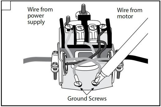
Wiring The Pressure Switch
1. Remove the switch Cover that installed the Pressure 2. Insert an electrical wire strain relief into the opening in
Switch. (Fig. 1) the opposite side of the pressure switch. (Fig. 2)
2
12 For Professional Technical Support call 1-844-242-24753. Pass the cable from the power supply through the strain 4. Connect the two wires from the power supply to the two
relief and tighten both screws on the strain relief. Do not outside terminals on the pressure switch (Fig. 4)
crush wire.(Fig. 3)
3 4
5. Connect the green ground wire from the power supply to 5
the green ground screw in the pressure switch (Fig. 4)
Risk of electric shock. Can shock, burn or kill. Connect ground wire before connecting power supply wires. Use the
wire size (including the ground wire) specified in the wiring chart. If possible, connect the pump to a dedicated branch
circuit (one with no other appliances on it).
Risk of explosion. Do not ground to a gas supply line.
WARNING: Risk of fire. Incorrect voltage can cause a fire or seriously damage the motor and voids the warranty. The
supply voltage must be within ±10% of the motor nameplate voltage.
NOTICE: For model WPD07501K / WPD10001K, motors voltage were set for 230 V. If necessary, reset the motor to the
desired voltage, as shown. Install, ground, wire, and maintain your pump in compliance with the National Electrical Code
(NEC) or the Canadian Electrical Code (CEC), as applicable, and with all local codes and ordinances that apply. Consult
your local building inspector for code information.
Wiring Chart – Recommended Wire and Fuse Sizes
Branch DISTANCE IN FEET FROM MOTOR TO SUPPLY
Max.
Motor Fuse 201 - 301 - 401 -
Volts Load 0 - 50 51 - 100 101 - 200
HP Rating 300 400 500
Amp
Amp
AWG WIRE SIZE (mm2)
10/14 8/14 8/14 6/12
3/4 115/230 15.8/7.9 20/15 14/14 (2/2) 14/14 (2/2)
(5/2) (7/2) (7/2) (9/3)
10/14 8/12 8/12 6/12
1 115/230 17.6/8.8 25/15 14/14 (2/2) 12/14 (3/2)
(5/2) (7/3) (7/3) (9/3)
PUMP PRIMING&STARTUP
Shallow Well Application Only
CAUTION: Risk of burns. Never run pump dry. Running pump without water may cause pump to overheat, damaging
seal and possibly causing burns to persons handling pump. Fill pump with water before starting.
WARNING: Risk of explosion and scalding. Never run pump against closed discharge. To do so can boil water inside
pump, causing hazardous pressure in unit, risk of explosion and possibly scalding persons handling pump.
For Professional Technical Support call 1-844-242-2475 131. Open the Pressure control valve completely
then remove the priming plug from the pump
and fill the pump, fill all piping between the
pump and the well, and make sure that all piping
in the well is full. If you have also installed a
priming tee in the suction piping, remove the
plug from the tee and fill the suction piping. (Fig.
1) (Fig. 2)
2. Open the faucet closest to the pump/tank a small amount to allow air to escape the system.
3. Power on! Start the pump.
4. If you don’t have water, stop the pump and remove the fill plugs. Refill the pump and piping. You may have to repeat
this two or three times in order to get all the trapped air out of the piping.
5. After the pump has built up pressure in the system and shut off, check the pressure switch operation by opening a
faucet or two and running enough water out to bleed off pressure until the pump starts. The pump should start when
pressure drops to 30 PSI and stop when pressure reaches 50 PSI. Run the pump through one or two complete
cycles to verify correct operation. This will also help clean the system of dirt and scale dislodged during installation.
Congratulations on a successful installation.
If you were unsuccessful, please refer to Troubleshooting or call our customer service technical staff.
Deep Well Application Only
CAUTION: All pumps must be primed (filling the cavity with water) before they are first operated. This may take several
gallons of water, as the suction line will be filled in addition to the pump cavity.
1. Open the Pressure control valve anti- clockwise as 2. Remove the 1/2” priming plug and priming tee plug. Fill
far as possible. (Fig. 1) pump cavity and pipe with water until it is full .Replace
1/2in. priming plug and priming tee plug. (Fig. 2)
Notes: Check to be sure water in pump cavity stays
constant. If water level goes down, it could indicate a leak
in the foot valve, check valve or suction pipe
3. Close Pressure control valve completely by turning 4. If pump is properly primed, pressure will quickly build
clockwise. Now start the pump.(Fig. 3) and register on the gauge mounted directly on the
pump body. If pressure does not build, repeat priming
operation. All air must be vented from the drive and
suction pipes as well as the pump cavity before the
pump will prime. The pump cavity may need to be filled
several times in order to achieve the prime. (Fig.4)
14 For Professional Technical Support call 1-844-242-24755. After the pump is primed and operate at a steady high
pressure, open two or more faucets and slowly
unscrew the flow control screw and pay attention to
the pressure on the pressure gauge until the pressure
value reaches the requirements of the following table.
This pressure will be minimum operating pressure.
The pressure value diverts the proper amount of water
to operate the ejector.
Adjust the Pressure control valve to the pressure listed in the chart below
HP Operating Pressure Setting
3/4 33 PSI
1 35PSI
The correct Pressure control valve setting will depend on the type of well installation and pressure switch setting for
the particular pump.
6. If pressure falls completely, retighten the flow control screw and readjust it according to step 5.
NOTE: If the pump is being used for shallow well applications, the flow control screw should be set in the full open
position.
IMPORTANT: If you don’t have water after 2 or 3 minutes, Turn power off at the breaker box. Look for leaks or a milky
color in the discharged water, which indicates an air leak. All connections must be water and air tight in order for pump to
operate. Re-prime if necessary, following steps 1 through 6 above.
Notes: If the pump has not been used for some time, be sure there is water in the pump housing (volute) and the piping
to the well.
CARE AND MAINTENANCE
WARNING: Disconnect power and release all pressure from the system before attempting to install, service, relocate or
perform any maintenance.
Winterizing
CAUTION: Drain the entire system if there is danger of
freezing. A drain plug is provided at the bottom of the pump
case for this purpose
Drain openings are provided on all models to drain the pump:
Unplug the pump from power supply outlet.
Remove drain plug close to the inlet hole.
Drain all piping to a point below the freeze line. This will
drain the pump.
NOTE: While this will drain the pump, it will not necessarily drain all the unprotected parts of the piping system. To drain
tank, disconnect the piping at the tank outlet.
SEAL ASSEMBLY REPLACEMENT
CAUTION: Make certain that the power supply is disconnected before attempting to service the unit! The rotary
seal assembly must be handled carefully to avoid damaging the precision lapped faces of the sealing
components.
1. Disengage pump body (Ref. No. 12) from motor mounting ring (Ref. No. 15).
2. Remove diffuser (Ref. No. 6).
3. Remove the rear cover(Ref. No. 17) .Remove the impeller(Ref. No. 5) use a 9/16" open end wrench to hold the motor
shaft.
4. The rotary seal (Ref. No. 4) will come loose at this time. Use a screwdriver (or similar instrument) to pry the silicon
carbide seal from the recess of the Seal plate (Ref. No. 2). Be careful not to damage the motor shaft or recess
surface.
For Professional Technical Support call 1-844-242-2475 155. Clean the recess and motor shaft thoroughly.
6. Install the new seal assembly.
a. Insert the silicon carbide seal and the rubber gasket into the recess of the Seal plate.
NOTE: To help facilitate installation, apply a drop of liquid soap to the outside diameter of the rubber gasket. Make
certain that the polished surface of mechanical seal and motor shaft are kept clean and free of dirt and/or oil.
b. Slip the remaining parts of the rotary seal assembly onto the motor shaft.
NOTE: Apply a drop of liquid soap to the inside diameter of the rubber drive ring.
7. Replace the impeller and diffuser removed in Steps 2 & 3.
8. Reassemble the pump body to the motor and mounting bracket.
ITEM DESCRIPTION QTY.
1 Motor 1
2 Seal Plate 1
3 O -ring 1
4 Mechanical Seal Assembled,E-5/8" 1
5 Impeller 1
6 Diffuser 1
7 Diffuser Ring 1
8 Control Valve Body 1
9 Flow Control Screw 1
10 Pressure Switch 1
11 Plug 1/8” NPT 1
12 Pump Body 1
13 Pressure Gauge 1
14 Lead Wire 1
15 Mounting Ring 1
16 Base 1
17 Rear cover
16 For Professional Technical Support call 1-844-242-2475TROUBLESHOOTING
For model: WPD07501K / WPD10001K
Problem Possible Cause Corrective Action
Pump does not start or 1. The switch is off. 1. Turn the power switch on.
run. 2. There is a blown fuse or tripped 2. Replace the fuse or reset the circuit breaker.
breaker. 3. DISCONNET THE POWER. File or clean the
3. The pressure switch contacts switch contacts.
are dirty. 4. DISCONNECT THE POWER.
4. The wires at the motor are loose Follow the wiring instructions to check and
or wired incorrectly. tighten the wires.
Pump will not prime. 1. The pump was primed 1. DISCONNECT THE POWER. Adjust pump
improperly or air is trapped in height and make the pipe slope down to the
the pipe. well. Remove the discharge tee and
2. There is an air leak. re-prime.
3. The water level is below the 2. Check all connections and fix the leakage.
suction pipe inlet. 3. Lower the suction pipe. If the water level is
4. The foot valve is plugged or more than 25 ft., use deep well installation.
leaks. 4. Clean or replace the foot valve.
Pump operates but pumps 1. The foot valve is buried in sand 1. Lift the suction pipe.
little or no water. or mud.
2. The ejector or impeller is 2. Clean the ejector or impeller.
plugged. 3. Clean or replace as necessary.
3. The foot valve or inlet strainer is
clogged. 4. Select a convertible jet pump.
4. The water level is below the
maximum lift specification. 5. Check the voltage switch.
5. The voltage is not correct. 6. Readjust the pressure regulator.
6. The pressure control valve is
not set up correctly.
Pump starts and stops too 1. The tank was pre-charged 1. Add or release air as needed.
often. incorrectly. 2. Replace the tank/refill the air.
2. There is a ruptured Test the tank by depressing the air valve.
diaphragm/bladder The air valve will expel water if the bladder is
(pre-charged tank)/or has no air broken.
cushion. 3. Repair the pipe connections or replace the
3. The pipes are leaking. pipes.
4. Repair or replace the foot valve.
4. The foot valve leaks. 5. Closely look at the pressure gauge to see the
5. The pressure switch is not pump On/Off points are around
adjusted correctly. 30 psi/50 psi. If not, adjust or replace the
6. The air charge is too low in the pressure switch.
pre-charged tank. 6. DISCONNECT POWER and open faucets
7. Standard pressure tank until all pressure is relieved. Using tire
(Conventional Type) is pressure gauge, check air pressure in the
waterlogged, and has no air tank at the valve stem located on the tank. If
cushion. less than pressure switch cut-in setting (30
psi), pump air into the tank from an outside
source until air pressure is 2 psi less than the
cut-in setting of the switch. Check the air
valve for leaks (use soapy solution) and
replace core if necessary.
7. Drain tank to air volume control port, check
AVC for defects.
Pump does not shut off. 1. Water level is lower than 1. Use a deep well installation.
estimated. 2. Locate and repair the leak or reconnect.
2. The pipes leak. 3. Reset or replace the pressure switch.
3. The pressure switch is not set 4. Remove the pump body and seal plate,
correctly. observe it
4. Venturi, nozzle or impeller is
clogged.
For Professional Technical Support call 1-844-242-2475 17For model: WPD07502K except for the upper ones, also included below:
Problem Possible Cause Corrective Action
Red light blinks: locked, Impeller blocked or debris goes Disassemble pump and clean debris.
overload, overheat around impeller.
Definition: when the overload is
detected for the first time, the
motor stops immediately, and
starts again 20 seconds later.
Repeat the detection for three
times until it stops completely
after overload.
Blue light blinks: dry run 1. Did not prime. 1. Please fill water into pump to prime.
Definition: when no-load is
detected for the first time, the
motor stops after 40 seconds of
operation, and starts again after
20 seconds. This is repeated for
3 time, and stops completely
after 3 times of no load.
Yellow light blinks: Rapid 1. The tank was pre-charged 1. Add or release air as needed.
cycle. incorrectly. 2. Replace the tank/refill the air.
Definition: It is detected that the 2. There is a ruptured 3. Repair the pipe connections or
motor has started 20 times within diaphragm/bladder (pre-charged replace the pipes.
1 minute, and it will stop tank)/or has no air cushion. 4. Repair or replace the foot valve.
immediately. 3. The pipes are leaking. 5. Closely look at the pressure gauge to
4. The foot valve leaks. see the pump On/Off points are
5. The pressure switch is not around 30 psi/50 psi. If not, adjust or
adjusted correctly. replace the pressure switch.
6. The air charge is too low in the 6. DISCONNECT POWER and open
pre-charged tank. faucets until all pressure is relieved.
Using tire pressure gauge, check air
pressure in the tank at the valve
stem located on the tank. If less than
pressure switch cut-in setting (30
psi), pump air into the tank from an
outside source until air pressure is 2
psi less than the cut-in setting of the
switch. Check the air valve for leaks
(use soapy solution) and replace
core if necessary
Green breathing light: Standby
Green light: Normal working
condition
18 For Professional Technical Support call 1-844-242-2475WARRANTY
Limited Warranty
WHAT THIS WARRANTY COVERS
When used and maintained in normal use and in accordance with the Owner’s Manual, your K2 product is warranted
against original defects in material and workmanship for at least one year (warranty varies depending on model; see box
for specific warranty information) from the date of purchase (the “Warranty Period”). During the Warranty Period, K2 will
repair or replace at no cost to you, to correct any such defect in products founds upon examination by K2 to be defective
in materials or workmanship.
Your dated receipt of purchase is required to make a warranty claim.
WHAT THIS WARRANTY DOES NOT COVER
This Warranty does not cover:
Use of the product in a non-residential application, improper installation and/or maintenance of the product, damage due
to misuse, acts of God, nature vandalism or other acts beyond control of K2, owner’s acts or omissions, use outside the
country in which the product was initially purchased and resale of the product by the original owner. This warranty does
not cover pick up, delivery, transportation or house calls. However, if you mail your product to an K2 Sales and Service
Center for warranty service, cost of shipping will be paid one way. This warranty does not apply to products purchased
outside of the United States, including its territories and possessions, outside of U.S. Military Exchange and outside of
Canada. This warranty does not cover products purchased from a party that is not an authorized retailer, dealer or
distributor of K2 products.
OTHER IMPORTANT TERMS
This warranty is not transferable and may not be assigned. This Warranty shall be governed and construed under laws
of the state of Michigan. The Warranty Period will not be extended by any replacement or repair performed under this
Warranty. THIS WARRANTY IS THE EXCLUSIVE WARRANTY AND REMEDY PROVIDED BY K2. ALL OTHER
WARRANTIES, EXPRESSED OR IMPLIED, INCLUDING WARRANTIES OR MERCHANTABILITY OR FITNESS FOR
PARTICULAR PURPOSE, ARE DISCLAIMED. IN NO EVENT WILL K2 BE LIABLE FOR ANY SPECIAL, INDRECT,
INCIDENTAL OR CONSEQUENTIAL DAMAGES OF ANY KIND OR NATURE TO OWNER OR ANY PARTY
CLAIMING THROUGH OWNER WHETHER BASED IN CONTRACT, NEGLIGENCE, TORT, OR STRICT PRODUCTS
LIABLITY OR ARISING FROM ANY CAUSE WHATSOEVER. Some states do not allow for the exclusion of
consequential damages, so the above exclusion may not apply to you. This warranty gives you specific rights. You may
also have others that vary from state to state.
Thank you for choosing a K2 product!
For Professional Technical Support call 1-844-242-2475 19Modelo: WPD07502K
WPD07501K
WPD10001K
MANUAL DEL PROPIETARIO
BOMBA JET CONVERTIBLE
WPD07502K WPD07501K/ WPD10001K
Pozos con diámetro interno de 4 pulg. o más
Expulsores incluidos para aplicaciones de pozos profundos
¿Preguntas, problemas, piezas faltantes? Antes de regresar a la tienda, llame al
servicio al cliente de K2 de lunes a viernes, de 08:00 a.m. a 6:00 p.m. EST
1-844-242-2475
www.K2pumps.comRENDIMIENTO
Cierre Pressure
GPM del agua @ presión de descarga total de 40 psi
de switch
Modelo# HP Voltage
0 10 20 30 40 50 60 70 80 90 100 110 presión
máxima ON OFF
pi. pi. pi. pi. pi. pi. pi. pi. pi. pi. pi. pi.
WPD07501K
3/4 20 16.3 12.1 6.7 6.3 5.1 4.0 3.0 2.5 1.8 - - 70PSI 230/115 30 50
/WPD07502K
WPD10001K 1 24 19.4 13.7 9 8.0 6.5 5.1 4.6 4.4 2.9 2 1.5 70PSI 230/115 30 50
INSTRUCCIONES DE SEGURIDAD
1. SOLO bombee agua limpia con esta bomba. No bombee líquidos inflamables o explosivos como el petróleo,
gasolina, kerosene, etanol, etc. No utilice en presencia de vapores inflamables o explosivos. El uso de esta bomba
con o cerca de líquidos inflamables puede provocar una explosión o incendio, que puede causar daños a la
propiedad, lesiones personales graves, y/o la muerte.
2. SIEMPRE desconecte la energía a la bomba antes de dar mantenimiento.
3. No toque la carcasa del motor durante su funcionamiento. El motor está diseñado para funcionar a altas
temperaturas. No desmonte la carcasadel motor.
4. No manipule la bomba o el motor de la bomba con las manos mojadas o cuando esté parado sobre una superficie
mojada o húmeda, o en agua.
5. Use gafas de seguridad en todo momento cuando trabaje con bombas.
6. Esta es una bomba de tensión dual de 115/230 V. Para el modelo: WPD07501K/WPD10001K, V VOLTAGE
SELECTOR INSIDE PRESET 230V.Pour la sélection 115V, se il vous plaît ouvrez le couvercle et réglez le
commutateur sur la tension appropriée. Tout le câblage doit être effectué par un électricien qualifié. Para el modelo:
WPD07502K, la bomba seleccionará automáticamente el voltaje apropiado. Todo el cableado debe ser realizado
por un electricista calificado.
7. Proteja el cable eléctrico de objetos afilados, superficies calientes, aceite y sustancias químicas. Evite doblar el
cable. No utilice cables dañados o desgastados.
8. Asegúrese de que la fuente de energía eléctrica sea adecuada para los requisitos de la bomba.
9. El incumplimiento de las instrucciones y del funcionamiento diseñado de esta unidad puede anular la garantía.
INTENTAR UTILIZAR UNA BOMBA DAÑADA puede causar daños a la propiedad, lesiones personales graves, y/o
la muerte.
10. La bomba debe conectarse a un circuito conectado a tierra equipado con un dispositivo interruptor de falla a tierra
(GFCI)
11. Conozca la bomba y sus aplicaciones, limitaciones y peligros potenciales.
12. Asegure la bomba a una base sólida.
13. Inspeccione periódicamente los componentes de la bomba y del sistema. Desconecte la bomba de la fuente de
alimentación antes de inspeccionar.
14. Siga todos los códigos eléctricos y de seguridad locales, junto con el Código Eléctrico Nacional (NEC). Además,
deben seguirse todas las reglas de la Administración de Seguridad y Salud Ocupacional (OSHA)
15. El motor de la bomba tiene un protector térmico automático de reajuste que se apaga si la bomba se recalienta.
Una vez que el protector térmico detecte que la bomba ha bajado de temperatura permitirá que la bomba funcione
normalmente.Si la bomba está conectada puede empezar a funcionar inesperadamente
16. Esta bomba está hecha de materiales de alta resistencia, resistentes a la corrosión. Proporcionará servicio sin
problemas durante mucho tiempo cuando sea instalada, mantenida y utilizada correctamente. Sin embargo, la
alimentación eléctrica inadecuada a la bomba, la suciedad o desechos pueden hacer que la bomba falle. Por favor,
lea atentamente el manual y sigas las instrucciones con respecto a los problemas y soluciones comunes de la
bomba.
17. Mantenga los dedos y objetos extraños lejos de la ventilación y otras aberturas. NO inserte ningún objeto en el
motor.
PRECAUCIÓN: No toque un motor en operación. Los motores modernos están diseñados para operar a
temperaturas altas. Para evitar quemaduras al realizar el servicio a una bomba, déjela enfriar por 20 minutos
22 Para comunicarse a Soporte técnico profesional llame al 1-844-242-2475después de apagarla
No permita que la bomba o cualquier componente del sistema se congele. Hacerlo invalidará la garantía.
Inspeccione la bomba y los componentes del sistema periódicamente.
El área de trabajo se debe mantener limpia, ordenada y con iluminación adecuada; guarde las herramientas y el
equipoque no utilice en el lugar apropiado.
Mantenga a los visitantes a una distancia segura de las áreas de trabajo.
ADVERTENCIA: Esta bomba está diseñada solo para instalación en interiores. Si no se instala en interiores,
aumentará significativamente el riesgo de lesiones o muerte por descarga eléctrica
PRE-INSTALACIÓN
APLICACIÓN
Esta unidad es una bomba de chorro convertible diseñada para bombear agua donde el nivel del agua es de hasta
90 pies para 3/4 HP o 110 pies para 1 HP. Para pozos de 25 pies o menos de profundidad, se deben adaptar las
instalaciones para pozos superficiales. Las instalaciones de pozos superficiales tienen una sola tubería entre la
bomba y el agua del pozo. Una bomba de chorro para pozo superficial tiene la boquilla y el venturi del sistema de
chorro integrados en la nariz de la bomba.
Para pozos de 25 pies a 110 pies de profundidad, se debe adaptar la instalación de pozos profundos. En este tipo
de configuración, la boquilla y el venturi se colocan en un paquete expulsor o "kit de chorro" que se coloca en el
pozo. Hay dos tuberías que van hacia el pozo. Una tubería extrae el agua hacia arriba (succión) mientras que la
otra tubería empuja el agua hacia abajo (propulsión) para hacer circular el agua a través de la boquilla y el venturi.
El agua que se mueve a través de esa boquilla y el venturi genera una presión diferencial que ayuda a llevar el
agua hacia la bomba.
Este número no debe exceder la profundidad nominal máxima de su bomba. Si lo hace, dificultará o impedirá en
gran medida el funcionamiento adecuado de la bomba.
HERRAMIENTAS NECESARIAS
Destornillador
Destornillador Sierra para
de Cabeza Llave para llave inglesa
de Phillips er metales
Plana
Medidor de
Gafas de Cinta Cinta de
presión de
Seguridad Métrica sellado
neumáticos
ESPECIFICACIONES
115V/230V, 60 HZ., 20/15 Amp Circuit (3/4HP).
FUENTE DE ALIMENTACIÓN
25/15 Amp Circuit (1HP)
RANGO DE TEMPERATURA DEL
32°F to 95°F (0°- 35°C)
LÍQUIDO
TAMAÑO DE DESCARGA NPT Hembra de 1 pg.
TAMAÑO DE SUCCIÓN NPT Hembra de 1-1/4 pg.
NIVEL DE AGUA DE POZO POCO
25 pi.
PROFUNDO
NIVEL DE AGUA DE POZO WPD07502K/ WPD07501K max. 90 pi.
PROFUNDO WPD10001K max. 110 pi.
DETERMINE LA PROFUNDIDAD DE SU BOMBA
Ate algo pequeño pero con peso, tal como el de un pez, en el extremo de un trozo de cuerda de algodón. Baje el peso
al pozo hasta que llegue al fondo del mismo. Haga una marca en la cuerda a nivel del suelo. Saque el peso del pozo y
Para comunicarse a Soporte técnico profesional llame al 1-844-242-2475 23mida desde la parte inferior del peso hasta la marca del nivel del suelo. Esta es la profundidad de su pozo. Este número
no debe exceder la profundidad nominal máxima de su bomba. Si lo hace, dificultará o impedirá en gran medida el
funcionamiento adecuado de la bomba.
UBICACIÓN DE LA BOMBA
Decida el área para la instalación de la bomba. Seleccione una ubicación de la bomba con espacio adecuado para el
futuro mantenimiento de la bomba. Solo destinada para uso en interiores, Puede ubicarse en el sótano o lavadero de la
casa, junto al pozo. Si se instala fuera de la casa, debe estar protegida por una casa de bombas con calor auxiliar para
evitar posible congelamiento. Proteja la bomba contra la intemperie, como el sol, la lluvia, el aguanieve, la nieve y
cambios extremos de temperatura. El pozo también debe protegerse por razones sanitarias. Monte la bomba tan ceca
del pozo como sea posible.
ALMACENAMIENTO EN TANQUES PRECARGADOS
La bomba del pozo debe montarse en un tanque de tipo precargado o convencional. Se recomienda un tanque de 20
galones, cuanto más grande mejor.. Lo mejor es tener éste en su lugar antes de instalar la bomba. Para un mejor
funcionamiento de la bomba, se recomienda que use un tanque de presión de diafragma (se vende por separado). Un
tanque de almacenamiento pre-cargado tiene una cámara flexible o diafragma que actúa como una barrera entre el aire
comprimido y agua. Esta barrera impide que el aire sea absorbido en el agua y permite que el agua actúe por aire
comprimido inicialmente a presiones atmosféricas mayores (pre-cargada). Se proporciona más agua utilizable que con
un tanque de tipo convencional.
La precarga debe ser de 2 PSI menos que el ajuste de cierre del interruptor de presión de la bomba.
NOTA: La bomba tiene un interruptor de presión de 30/50 psi, lo que significa que el "corte" es de 30 psi; por lo tanto, el
tanque debe configurarse a 28 psi. Para verificar la presión en el tanque, use un medidor de presión de neumáticos (no
incluido). Si se necesita más aire, agregue aire al tanque con una bomba de neumáticos o un compresor de aire. Si se
necesita menos aire, purgue aire.
PRECAUCIÓN: Para que la bomba y el tanque funcionen correctamente, el tanque de presión tiene que ser drenado de
toda el agua ANTES DE INSTALAR LA NUEVA BOMBA. Después del drenaje, si está utilizando el interruptor de presión
suministrado de 30/50 psi en los ajustes preestablecidos, añada o ajuste la presión de aire en el tanque a 28 psi de
presión ANTES del arranque.
PREPARACIÓN
Las partes que podría necesitar para el ensamble no están incluidas (Fig. 1)
Articulo Descripción Articulo Descripción
Válvula de pie de latón de Adaptador macho de PVC MPT×S
1
1 12
1-1/4 pulg. de 3/4 pulg.
Adaptador macho de PVC Tubo rígido de PVC de 3/4 pulg.
2 13
MPT×S de 1-1/4 pulg.
Tubo rígido de PVC de Accesorio en Te ciega CPVC CTC
3 14
1-1/4 pulg. de 3/4 pulg.
Cierre de pozo de bomba Codo S x S de 90 grados de PVC de
4 15
única 3/4 pulg.
Adaptador macho de PVC Válvula de pie de latón de 1-1/2 pulg.
5 16
MPT×S de 1 pulg.
válvula de retención de latón Boquilla de acero galvanizado
6 17
sin plomo de 1-1/4 pulg. 1-1/2 pulg. × 3 pulg.
Boquilla de acero Boquilla de acero galvanizado
7 galvanizado 1-1/4 pulg. × 18 1 pulg. × 3 pulg.
3 pulg.
adaptador hembra de PVC adaptador hembra de PVC FPT × S
8 19
FPT × S de 1-1/4 pulg. de 1 pulg.
Tubo rígido de PVC de Tubo de doble sello para pozo de
9 20
1 pulg. 4 pulg.
Codo S x S de 90 grados de TE DE PVC FPT×FPT×FPT de
10 21
PVC de 1 pulg. 1-1/4 pulg.
Adaptador reductor macho Tapón galvanizado de 1-1/4 pulg.
11 22
de PVC de 1 pulg. × 3/4 pulg.
24 Para comunicarse a Soporte técnico profesional llame al 1-844-242-2475Las partes opcionales para el ensamble no están incluidas (Fig. 2)
Articulo Descripción Articulo Descripción
válvula de bola deslizante x
2
1 5 Tanque de 20 gal. o más
deslizante de 3/4 pulg.
Unión deslizante x deslizante de punto del pozo,
2 PVC de 1-1/4 pulg. 6 Acople de transmisión del pozo,
Tapa para cañería del pozo
unión de PVC FPT × FPT de
3 3/4 pulg. 7 1/8in.AVC control kit
Acoplamiento PVC de1-1 / 4 pulg.
4 Acoplamiento PVC de1 pulg. Kit de control 1/8 pulgada AVC
Acoplamiento PVC de 3/4 pulg.
INSTALACIÓN DE LA APLICACIÓN PARA EL POZO
Solo aplicación para pozo superficial
Los sistemas de pozos superficiales se identifican mediante una tubería que va al pozo, lago o río.La bomba de chorro
convertible se puede usar para pozos superficiales (25’ o menos), con el conjunto de chorro de pozos superficiales.
1. APLICACIÓN PARA POZO ENTUBADO, ENTUBADO DE 4” O MÁS
(Fig. 1)
Un orificio perforado en la tierra con maquinarias. Las profundidades
oscilan entre unos pocos pies y 25 pies. Los diámetros comunes de
pozos son de 4’’, 5’’, 6’’ y 8’’. para pozos de agua doméstica.
2. APLICACIÓN DE PUNTO DE POZO (PUNTO ACCIONADO) (Fig. 2)
La tubería con un filtro en punta se introduce en el suelo debajo de la
capa freática. La profundidad habitualmente es inferior a 25 pies. Los
diámetros disponibles son de 1’’. a 2’’.
3. APLICACIÓN PARA AGUA SUPERFICIAL (Fig. 3)
Una tubería va al lago, río, cisterna o estanques, la elevación por succión
es inferior a 25'.Instale un filtro alrededor de la tubería de entrada para
evitar el atrapamiento de nadadores, vida silvestre y escombros.
PRECAUCIÓN: Posible contaminación. No use aguas superficiales para
beber. La instalación que se muestra podría usarse para aplicaciones de
rociadores.
Para comunicarse a Soporte técnico profesional llame al 1-844-242-2475 25Para aplicación en pozos profundos (Sistema de doble
tubería)
Un orificio perforado en la tierra con maquinarias.La profundidad es
mayor de 25 pies. Los diámetros comunes de pozos son de 4’’. , 5’’. , 6’’. y
8’’ para pozos de agua doméstica.
Los sistemas de pozo profundo se identifican por dos tuberías que van al
pozo, una tubería de succión y una tubería impulsora. La bomba de
chorro convertible se puede usar para pozo profundo (más de 25'), con un
conjunto de chorro de pozo profundo en el pozo. La tubería de succión y
la tubería de propulsión están unidos al conjunto del chorro.
INSTALACIÓN
La tubería flexible está prohibida en la tubería de succión (tubería de entrada). Se pueden instalar uniones o
acoplamientos de manguera cerca de la bomba para facilitar la extracción para el mantenimiento o el almacenamiento.
Una manguera de goma instalada entre el sistema de agua y la tubería de la casa reducirá el ruido transmitido a la casa.
1. INSTALACIÓN DE LA TUBERÍA EN EL POZO
Solo aplicación para pozo superficial
PRECAUCIÓN: Ajuste todo el conjunto en seco para garantizar un ajuste adecuado antes de pegar o encintar las
piezas. Siga todos los procedimientos adecuados de adhesión según lo especificado por el fabricante del adhesivo.
Siempre coloque adhesivo en dirección vertical en la medida de lo posible para evitar que el pegamento gotee dentro de
la tubería o los accesorios. Use cinta de tubería y compuesto de pasta de tubería en todas las roscas macho. Apriete
con la llave para un ajuste perfecto y agregue otro 1/4 de vuelta para asegurar un sellado adecuado.
Para instalación en pozo entubado
1. Conecte la válvula de pie de latón de 1-1/4 pulg. al 2. Instale el sello del pozo sobre una tubería rígida de
adaptador macho de PVC MPT × S de 1-1/4 pulg. PVC de 1-1/4 pulg. y en el entubado del pozo.
Cemente el adaptador a una tubería rígida de PVC de Coloque la válvula de pie 5 pies por encima del fondo
1-1/4 pulg. Todas las conexiones deben ser del pozo y al menos 10 pies por debajo del nivel de
herméticas al aire y al agua para que la bomba agua del pozo. (Fig. 2)
funcione correctamente. (Fig. 1)
3. Cemente el adaptador macho de PVC MPT × S de
1-1/4 pulg. en la parte superior de la tubería.Instale la
Te de PVC FPT × FPT × FPT de 1-1/4 pulg. en el
adaptador. Un extremo del puerto se instala en otro
adaptador macho de PVC MPT × S de 1-1/4 pulg.
Agregue secciones a las tuberías para llegar a la
adaptador. (Fig 3)
26 Para comunicarse a Soporte técnico profesional llame al 1-844-242-2475Instalación del punto de pozo
Hinque el pozo utilizando “manguitos de tubería de hincar” y una “caperuza para la hinca”. Las “conexiones de perforar”
están roscadas a todo lo largo y permiten que los extremos de la tubería empalmen para que la fuerza de perforación
del mazo sea soportada por la tubería y no por el enroscado. Las conexiones ordinarias que se encuentran en las
tlapalerías no están roscadas a todo lo largo y se pueden colapsar por el impacto. Las “conexiones de hincado” también
son más suaves que las conexiones de plomería comunes, y esto facilita la penetración en el suelo.
1. Conecte un acople de transmisión de 1-1/4 pulg. al 2. Enrosque la válvula de retención de latón sin plomo
punto del pozo. Enrosque la tubería de acero de 1-1/4 pulg. en la boquilla de acero. Instale la
galvanizado de 1-1/4 pulg. en el acople de boquilla de acero galvanizado de 1-1/4 pulg. en la
trasmisión. (Fig. 1) válvula de retención. (Para cebar fácilmente,
conecte la válvula de retención lo más cerca posible
del pozo) (Fig. 2)
3. Instale la Te de PVC FPT × FPT × FPT de 1-1/4 pulg.
en la boquilla. Un extremo del puerto horizontal se
instala en otro adaptador macho de PVC MPT × S de
1-1/4 pulg. y la tubería rígida de PVC de 1/4 pulg.
Agregue secciones a las tuberías para llegar a la
unión deslizante x deslizante de PVC de 1-1/4 pulg.
(opcional). (Fig. 3)
Instalacion para agua superficial
1. Conecte la válvula de pie de latón de 1-1/4 pulg. al 2. Instale el filtro alrededor de la válvula de pie, proteja el
adaptador macho de PVC MPT × S de 1-1/4 pulg. conjunto de la válvula de pie contra pescado,
Cemente el adaptador a una tubería rígida de PVC de residuos, etc. Coloque la válvula de pie 5 pies por
1-1/4 pulg. Todas las conexiones deben ser encima del fondo del pozo y también debe estar al
herméticas al aire y al agua para que la bomba menos 10 pies por debajo del nivel del agua para
funcione correctamente. (Fig. 1) evitar que la bomba succione aire. (Fig. 2)
Para comunicarse a Soporte técnico profesional llame al 1-844-242-2475 273. Cemente el adaptador macho de PVC MPT × S de
1-1/4 pulg. en una tubería rígida de PVC de
1-1/4 pulg. Instale la Te de PVC FPT × FPT × FPT de
1-1/4 pulg. en el adaptador. Un extremo del puerto
horizontal se instala en otro adaptador macho de PVC
MPT × S de 1-1/4 pulg. y la tubería rígida de PVC de
1/4 pulg. Agregue secciones a las tuberías para llegar
a la unión deslizante x deslizante de PVC de
1-1/4 pulg. (opcional). (Fig. 3)
Solo para aplicación en pozos profundos (pozo de 4” o más grande)
1. Instale la válvula de pie de latón de 1-1/2 pulg. en la
boquilla de acero galvanizado de 1-1/2 pulg. × 3 pulg.
Conecte el conjunto de boquilla/válvula de pie a la
parte inferior del cuerpo del expulsor. Luego instale la
boquilla de plástico y el venturi en la parte superior del
cuerpo del expulsor. Todas las conexiones deben ser
herméticas al aire y al agua para que la bomba
funcione correctamente. (Fig. 1)
Nota: Seleccione la boquilla y el venturi en diferentes
profundidades de agua debajo del cuadro.
Cuadro del paquete de chorro de tubería doble
Profundidad máxima del agua en pies.
Modelo# HP Límite de Límite de Boquilla
Boquilla Venturi
profundidad profundidad Venturi
3/4 25-70 #51 J32P-24 70-90 #54 J32P-20
1 25-70 #51 J32P-24 70-110 #54 J32P-20
2. Instale un adaptador macho de PVC MPT × S de
1-1/4 pulg. en el cuerpo del expulsor sobre el venturi
de plástico. Luego instale una boquilla de acero
galvanizado de 1 pulg. × 3 pulg. en el cuerpo del
expulsor, seguido de un adaptador hembra de PVC
FPT × S de 1 pulg. Cemente las tuberías rígidas de
PVC de 1 pulg. y 1-1/4 pulg. en el adaptador. (Fig. 2)
3. Instale un sello de pozo de 4 pulg. sobre una tubería 4. Cemente el codo S × S de 90 grados de PVC de
rígida de PVC de 1 pulg. y 1-1/4 pulg. Coloque la 1 pulg. a la parte superior de la tubería rígida de PVC
válvula de pie al menos a 5 pies sobre el fondo del de 1 pulg. Cemente el adaptador macho de PVC MPT
pozo y 10 pies debajo del nivel de agua del pozo. × S de 1-1/4 pulg. a la parte superior de la tubería
Corte la parte superior de la tubería rígida de PVC de rígida de PVC de 1-1/4 pulg. e instale la te de PVC
1 pulg. y la tubería rígida de PVC de 1-1/4 pulg. La FPT × FPT × FPT de 1-1/4 pulg. al adaptador. Un
compatibilidad de las tuberías para el siguiente paso extremo del puerto horizontal se instala en otro
de la instalación se muestra en el diagrama de adaptador macho de PVC MPT × S de 1-1/4 pulg. Se
instalación. (Fig. 3) muestra la instalación completada. (Fig. 4)
28 Para comunicarse a Soporte técnico profesional llame al 1-844-242-2475You can also read