INSTALLATION, OPERATION AND MAINTENANCE GUIDE - Hammond ...
←
→
Page content transcription
If your browser does not render page correctly, please read the page content below
INSTALLATION, OPERATION AND MAINTENANCE GUIDE

   FOR INDOOR/OUTDOOR DRY-TYPE TRANSFORMERS
WHICH UTILIZE A DH STYLE OR POWER SERIES ENCLOSURE

   *Note: This guide is Trilingual   Literature No.: IOMGPOW
     (English, French, Spanish)*          Issue Date: March 2020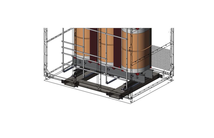
Page 2

                           Safety Precautions
1. Do not lift or move a transformer without proper equipment and experienced
   personnel. Lifting provisions are provided inside of the enclosure on the core/coil
   only. Always use lifting provisions provided by the manufacturer. DO NOT LIFT THE
   TRANSFORMER BY THE ENCLOSURE. Rolling and skidding are recommended on
   transformers with a pre-ordered skidding base (see figure 9).

2. Do not off-load the transformer until a full inspection has been completed.

3. Only use terminals for electrical connections. Flexible connectors are recommended
   for bus connections. The transformer terminals are not designed to support the
   weight of line or load cable. Uni-strut supports can be added in the field providing
   proper clearances are maintained.

4. Cover the core and coil with a suitable protective drop cloth if there is drilling,
   grinding, or painting to be done.

5. Connections should only be made in accordance with the nameplate diagram or
   connection drawings.

6. Make sure all power (including back-fed control, shared neutral and capacitor charge)
   is disconnected and all windings are grounded before attempting any work on the
   transformer or inside the control box.

7. Make certain all ground connections, line terminals and selected tap connections are
   complete and tightened before energizing the transformer.

8. Do not attempt to change any primary or secondary connections or taps while the
   transformer is energized.

9. Do not tamper with control panels, alarms, interlocks, or control circuits.

10. Do not adjust or remove any accessories or cover plates while the transformer is
    energized.

11. No supply cables (including shielded cables) should come in contact with the core or
    coil or any live part except the terminal that it is intended for. Ensure that minimum
    clearances are maintained. (refer to Field Testing section)

12. This equipment must only be installed and serviced by qualified electrical personnel.

13. Follow all requirements in NFPA 70E and CSA 462 for safe work practice and personal
    protective equipment (PPE).

14. Replace all devices, doors, and covers before turning on power to this equipment.

15. You are not allowed to perform any modification to the equipment (as this may affect
    warranty and cause a hazardous situation) without HPS’s prior authorization.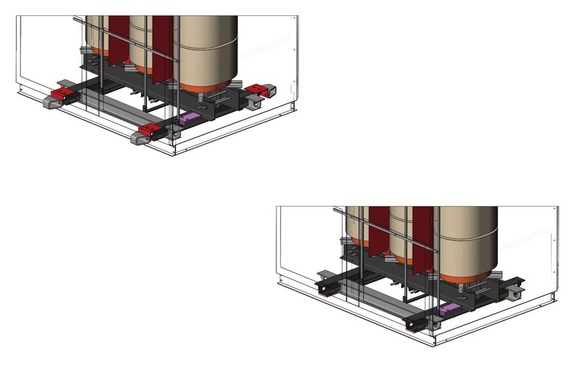
Page 3

                CONTENTS

Scope                      4
Receiving & Inspection     4
Lifting Procedures         4
Storage                    6
Installation precautions   6
Dry-out                    7
Location                   8
Sound Levels               9
Grounding                  9
Field Testing              9
Maintenance                11
Cleaning                   11
Field Service              12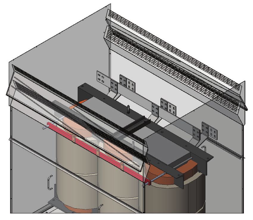
Page 4

                      SCOPE                               Once the unit has been received, remove the covers
                                                          or panels and proceed with an internal inspection for
This guide covers the recommendations for the             any evidence of damaged or displaced parts, loose
application, installation, operation and maintenance      or broken connections, damaged terminal boards, dirt
of single and three phase dry-type transformers and       or foreign materials and for the presence of any water
iron core reactors with or without enclosure. It is       or moisture. If any damage is evident, contact the
emphasized that these abbreviated instructions should     transformer manufacturer and/or your representative
be used in conjunction with all standards covering        immediately.
such work and should be referenced accordingly.
These recommended practices are for general                        LIFTING PROCEDURES
applications and any special requirements should be
referenced back to the transformer manufacturer and/      Lifting provisions are provided on all dry-type transformers.
or their representative.                                  Lifting provision can be 2 or 4 of 5/8” (16 mm) or 3/4”
                                                          (19 mm) shouldered eye bolts or a pair of lifting angles
It is further recommended that installation work be
                                                          (see figure 1) based on the total weight of transformer.
governed by ANSI/IEEE C57.94. This is the IEEE
                                                          Shouldered eye bolts used for the unit weight is less than
Recommended Practice for Installation, Application,
                                                          15,000 lbs (6,804 kgs). Lifting angles used for the unit
Operation and Maintenance of Dry-type General
                                                          weight is 15,000 lbs (6804 kgs) and greater. Use of slings
Purpose Transformers.
                                                          for an angular lift is strongly recommended.

       RECEIVING & INSPECTION
Before any equipment is off-loaded, transformers
should first be inspected for correctness of shipping
information. Confirm that the identifying part number
on the nameplate of the transformer matches the           Shouldered                            Lifting Angle
                                                          Eye Bolts
packing list and Bill of Lading.
                                                                                 FIGURE 1
Inspect the transformers immediately upon receipt for
evidence of damage or indication of rough handling        Procedure
that may have been caused during shipment.                Before a lift is made, the following instructions should be
Examination should be made before removing                read and understood.
transformers from shipping vehicles. Inspection should    (1) Remove the roof of DH type of enclosure (see figure
also be made for any evidence of water or other               2) or lifting cover plate on roof of power enclosure
contaminants that may have entered the transformer            (see figure 3).
during transit.
A claim should be filed with the carrier at once and
the manufacturer should be notified.
Ventilated dry-type transformers are shipped either
completely assembled in a sheet metal enclosure or
as a core and coil assembly with or without a separate
enclosure. All parts and components are wrapped
in clear plastic sheets and covered with a shipping
tarpaulin. Drawings may also accompany the shipment
in a separate package that detail assembly if required.

                                                                                  FIGURE 2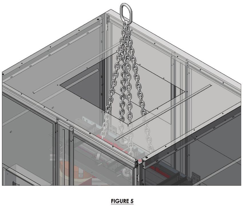
Page 5
REMOVE THE COVER
PLATE
FIGURE 3
(2) Inspect that the lifting eye bolts or lifting angles are
properly seated and tight.
(3) Verify lifting capacity of chains or slings, crane or
other means refer to the weight of transformer on
the nameplate.
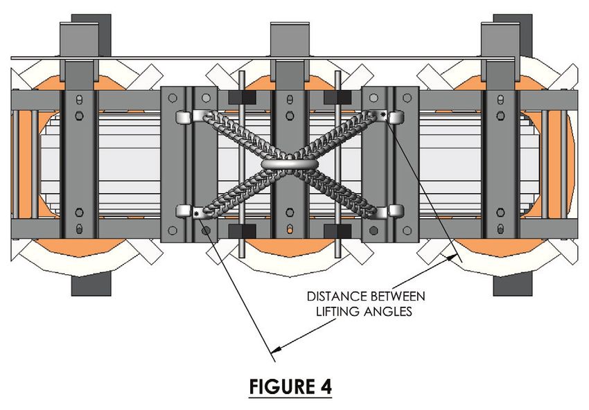
(4) Measure the distance between the eye bolts or lifting
angles (see figure 4 & 5).
FIGURE 6
TABLE 1
*Eye Chain Length (ft)
Center 33’ 4’ 5’ 6’ 7’ 8’ 9’ 10’’
10” 82° 84° 85° 86° 87° 87° 87° 88°
DISTANCE 12” 80° 83° 84° 85° 86° 86° 87° 87°
BETWEEN
EYE BOLTS 14” - 82° 83° 84° 85° 86° 86° 87°
16” - 80° 82° 84° 85° 85° 86° 86°
FIGURE 4 18” - - 81° 83° 84° 85° 85° 86°
Inches
20” - - 80° 82° 83° 84° 85° 85°
22” - - - 81° 82° 83° 84° 85°
24” - - - 80° 81° 82° 84° 84°
26” - - - 80° 81° 82° 83° 84°
28” - - - - 80° 82° 83° 83°
30” - - - - 80° 81° 82° 83°
32” - - - - - 80° 81° 82°
34” - - - - - 80° 81° 82°
DISTANCE BETWEEN
LIFTING ANGLES 36” - - - - - - 80° 81°
*Note: Distance between lifting eyes on front and
FIGURE 5 rear frames
(5) Ensure that the sling angle is less than 10 degrees
(see figure 6 & table 1).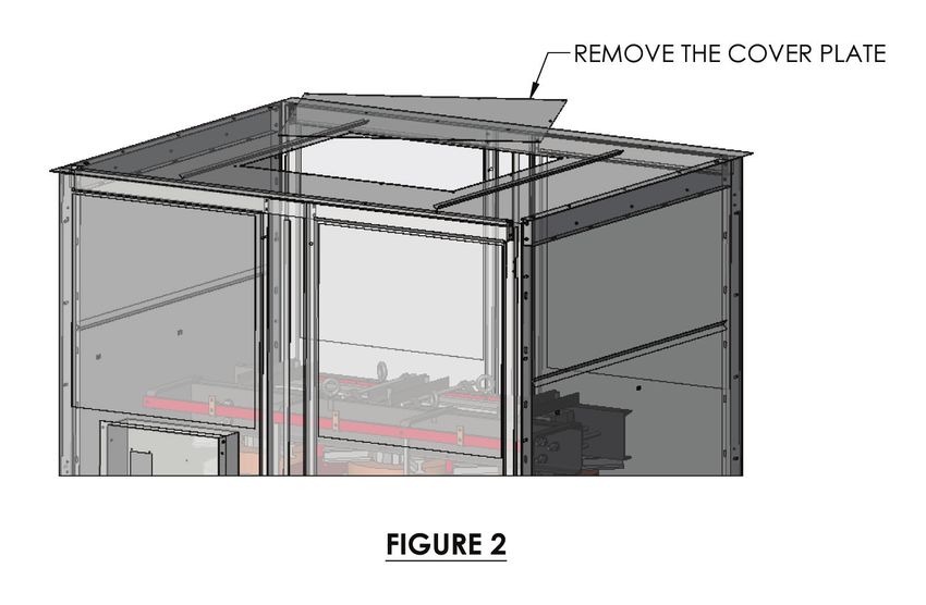
Page 6
(6) The direction of the pull (sling line) must be in-line STORAGE
with the plane of the eye bolts. When lifting a
transformer with a 4-legged sling, align all four Units must be stored in a warm, dry location, free of
eyebolts to the center of the unit (see figure 5). dust or air borne contaminants. The relative humidity
When lifting a unit with a 2-legged sling, ensure to which the electrical insulation materials are exposed
that the eye bolts are installed at opposite corners should be kept as low as practical. It is preferred to
of the unit and align to the center of the unit (see store in warm dry location to avoid moisture issues
figure 7). but may be able to be stored in temperature to -40°C
(-40°F). Transformer may be energized when the
coil temperature is as low as -25°C (-13°F) but it is
recommended they not be loaded until the coils reach
0°C (32°F). Fluctuating temperatures can cause
condensation issues requiring a Dry-Out procedure.
The floor on which the transformer is stored should
be impervious to the upward migration of water vapor.
Take precaution to guard against water from any
source such as roof leaks, broken water or steam
FIGURE 7
lines, windows, etc. It is not recommended that dry-
(7) Always use all the eye bolts or lifting holes
type units be stored outdoors. If that is unavoidable,
provided in angles when making a lift to avoid
units must be well protected from snow, rain and other
overrating of bolts or torsion of frames.
elements. Protection should include an initial wrap
of first quality canvas with a final outside covering of
plastic tarpaulin. It would also be desirable to include a
desiccant such as a silica gel dry-out system to reduce
the moisture content inside the assembly. If units are
stored outdoors, dry-out is recommended as described
on the following page.
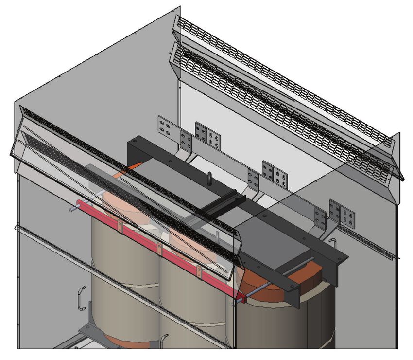
INSTALLATION PRECAUTIONS
(1) It is recommended that anti-vibration pads or
other vibration isolation devices be present when
installing dry-type transformer. Some dry-type
FIGURE 8
transformers may have pre-installed anti-vibration
(8) Lift the power transformer by core & coil only pads or other vibration isolation devices. Most
through cutout in enclosure roof (see figure 8). of the time the anti-vibration pads are provided
Do not lift transformer by the enclosure. with the dry-type transformers and need to be
Do not lift power transformer with shipping hooks. installed on site. When installing the anti-vibration
Do not lift transformer from beneath the enclosure. pads beneath transformer base beam, ensure
Do not jerk lift to avoid mechanical stresses. that lifting the transformer by core & coil only. If
Do not push, drag or pull the transformer directly on the enclosure is provided and attached to the
the floor unless it is supplied with skid base. core & coil by shipping angles, make sure that the
shipping hooks and shipping angles are removed
in all locations (see figure 9 and 10) and then lift
the transformer by core & coil only to install the
anti-vibration pads (or other vibration isolations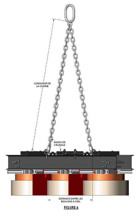
Page 7
(5) Use of flexible connectors for bus connections is
required per design).
recommended.
6+,33,1*$1*/(6
SHIPPING JACKING LOCATIONS ON EITHER
-$&.,1*/2&$7,21621(,7+(5
ANGLES
6+,33,1*$1*/(6 SIDE OF BOTTOM CHANNELS
6,'(2)%27720&+$11(/6
-$&.,1*/2&$7,21621(,7+(5 ANTIVIBRATION
$17,9,%5$7,213$'6 PADS
6+,33(':,7+75$16)250(5
6,'(2)%27720&+$11(/6 (SHIPPED WITH TRANSFORMER)
$17,9,%5$7,213$'6
ROLLING AND SKIDDING BASE
52//,1*$1'6.,'',1*%$6(
6+,33(':,7+75$16)250(5
52//,1*$1'6.,'',1*%$6(
FIGURE 9
)LJXUH
IRUERWK93,DQG&DVWPDQXDO
3,DQG&DVWPDQXDO
(6) Recommend the supply cables come in from
bottom and/or side and shall not block ventilation
openings.
(7) If any drilling needs to be done, please ensure
)LJXUHIRUERWK93,DQG&DVWPDQXDO that core and coil assembly must be protected by
$17,9,%5$7,213$'6
,1),1$//2&$7,21
)LJXUHIRUERWK93,DQG&DVWPDQXDO ANTIVIBRATION
$17,9,%5$7,213$'6 PADS
(IN,1),1$//2&$7,21
FINAL LOCATION) a cover sheet (e.g. Tarp) so that nothing can land
FIGURE 10 on or in coil during or after drilling and when cover
sheet is removed.
DRY-OUT
If a transformer has been exposed to moisture
such as condensation or rain, or stored in a high
JACKING LOCATIONS ON
-$&.,1*/2&$7,21621(,7+(5
EITHER SIDE OF BOTTOM
6,'(2)%27720&+$11(/6 humidity environment, the unit must be dried out
CHANNELS
FORKLIFT
WITH 4 WAY
TUBES
)25./,)778%(6:,7+
SKIDDIN
:$
Page 8

    These heaters should be located under the               they are de-energized for appreciable periods. Refer
    windings on both sides of the core. If heaters are      to dry out instructions. Dry-type units covered by this
    used, air circulation through the enclosure must        guideline are designed for operation at altitudes not
    still be permitted. Fiberglass furnace filters may      exceeding 1000 m (3300 ft.) unless transformer has
    be mounted temporarily over the inlet and outlet        been specifically designed for higher altitude.
    ventilation openings to minimize dust accumulation      Environmental Considerations:
    within the enclosure. These filters must be
                                                            Ventilated dry-type transformers should not be
    removed before the transformer is put into service.
                                                            located in environments containing contaminants
    Recommended temperature should not exceed
                                                            including dust, fertilizer, excessive moisture,
    105°C (221°F).
                                                            chemicals, corrosive gases, oils or chemical vapors.
(4) For dry-out using internal heating through the          Locations where dripping water is present are to be
    shorted terminal method, please contact the             avoided. If this is not possible, suitable protection
    transformer manufacturer for specific instructions.     must be provided to prevent water from entering the
    The principles of this method require to short          transformer enclosure.
    circuit LV and supply current to HV no more than        Dry-type transformer should not be installed in areas
    100% of nameplate current rating. The winding           accessible to the public unless specially designed for
    temperature should not exceed 105°C (221°F)             that.
    refer to section 4 of Field Testing.
                                                            Dry-type transformers can be located outdoors,
(5) Variable factors affecting the construction and         but they must be designed especially for outdoor
    use of dry-type transformers makes it difficult to      environmental protection. Suitable weather resistant
    set limits for the insulation resistance. Experience    and tamper-proof enclosures are required in locations
    to date indicates that 2 megohms, (one minute           where there is driven water, snow, dust and sand
    reading at approximately 25°C) per 1000 volts of        particles should be avoided. Consult the transformer
    nameplate voltage rating, but in no case less than      manufacturer for further information.
    2 megohms total, may be a satisfactory value for        Transformer with open bottom, should not be installed
    insulation resistance. Insulation megger test (500      on or over combustible surfaces.
    V or 1000 V DC). Tests to be done between:
                                                            Ventilation:
    		           LV to HV + Ground
                                                            Transformers must be located at least 2 feet away
    		           HV to LV + Ground                          from walls, obstructions, adjacent transformers or
                 Core to Ground (if the core is isolated)   other reflecting surfaces on ventilation side unless
It is emphasized that only specifically qualified           otherwise marked. Or further if there is another
personnel undertake this work.                              heat source.
Transformers that have been exposed to flood                Directed air in the room near the transformer can
conditions, direct rain or sprinklers, may not be able to   disturb the natural air flow for cooling through the
be dried out appropriately. Consult the manufacturer        winding.
for further instructions.                                   Adequate ventilation is essential for the proper cooling
                                                            of transformers. Clean, dry air is desirable. If the
                    LOCATION                                location has unusually high airborne contaminants,
                                                            optional filters may be required. If transformers are
Ventilated dry-type transformers normally are designed      installed in vaults or other places with restricted air
for installation indoors in dry locations. They will        flow, sufficient ventilation shall be provided to maintain
operate successfully where the humidity is high,            correct air temperatures. The limits are specified
but under this condition it may be necessary to take        by CSA or ANSI standards and are measured near
precautions to keep them dry from condensation if
Page 9

the transformer ventilation openings. The area of          in more confining electrical rooms which will have
ventilation openings required depends on the height        the effect of increasing the apparent sound level.
of the vault or transformer room and the location of       Transformers will exhibit higher than normal sound
transformer ventilation openings. For self-cooled          levels if installed on suspended floors that may
transformers, the required effective area must be at       resonate. It is a good practice to install power units on
least one square foot each of inlet and outlet per 100     the ground floor or basement level to avoid suspended
kVA of rated transformer capacity, after deduction of      floors and away from office or living quarters. Vibration
the area occupied by screens, gratings, or louvers.        dampeners or spring isolators are also recommended
This is necessary to provide sufficient free circulation   to attenuate sound levels.
of air through and around each unit. This will also        Flexible connectors can be installed between the bus
permit ready access for maintenance.                       bars and other equipment to avoid vibration transfer.
If the transformer is to be located near combustible       Ensure all mounting bolts are tightened and that
materials, the minimum distance established by The         the transformer housing is securely assembled and
Local Electrical Code should be maintained.                separate from the transformer itself.
                                                           Transformers installed in close proximity to each other
               SOUND LEVELS                                can experience a resonant frequency between them
                                                           that results in higher than normal sound levels.
The audible sound produced by transformers is due
                                                           If noise levels are a factor in the location of any
to energizing of the core by the alternating voltage
                                                           transformer, special consideration should be given
applied to the windings. This creates vibrations
                                                           to the installation site and attenuation equipment.
whose fundamental frequency is twice the frequency
                                                           Interrupting the sound transmission medium with the
of the applied voltage. The vibrations producing
                                                           installation of sound absorbing foam or fiberglass
audible sound can occur in the core mounting and
                                                           material on the ceiling or walls, could be considered.
in the housing. The transmission of sound from
the transformer can be by various media such as
air, metal, concrete, wood or any combination.
                                                                             GROUNDING
Amplification of audible sound can occur in a given
                                                           All non-current carrying metal parts in transformers
area due to the presence of reflecting surfaces or
                                                           must be grounded, including the core and enclosure.
mounting surfaces.
                                                           Standard construction has the core grounded through
Sound levels for transformers can vary from 60 dBA         direct contact with the clamping structure. Cores that
for a 500 kVA to 76 dBA for a 10,000 kVA and more.         have metal bolts passing through them are insulated
These sound levels are determined by CSA and               from the core clamps and grounded at a single point.
ANSI Standards and are based on the following:             Isolating the core in this manner is necessary on
•   Sound levels specified are for a non-loaded            these transformers only to determine if there is an
    condition at rated voltage and frequency               insulation failure in any through-bolts that might cause
                                                           a high circulating current or hot spot. There are no
•   Units are tested in a low ambient noise
                                                           requirements for isolating cores in any standards
    environment
                                                           including UL, ANSI, CSA, IEEE and IEC.
•   Walls or reflecting surfaces are at least 10'
    away from all sides of the transformer.                                FIELD TESTING

It should be noted therefore that operating                It is recommended that separate field testing and
transformers when connected to a load, will exhibit        inspection be made before placing a transformer in
higher sound levels than the standards referenced.         service to determine that it is in satisfactory operating
Additionally, transformers are frequently installed        condition and to obtain data for future comparison.
                                                           Tests and procedures as recommended in ANSI/IEEE
Page 10

is recommended as a minimum.                                    block. For winding > 30kV BIL, do not put probe in
Where low-frequency applied-voltage, induced-                   the coil unless instructed to do so.
voltage, insulation resistance or megger, for
acceptance are conducted the test voltages shall not
exceed 75% of factory test values. When field tests
are made on a periodic basis, it is recommended
that the test voltages be limited to 65% of factory test
values. Disconnect surge arrestors if supplied. It is
emphasized that any tests should be conducted by
                                                                Thermowell stick type            Thermowell tube type
competent or qualified personnel in accordance with
recognized safety standards and codes, particularly         (5) Check for tightness and cleanliness of all electrical
NFPA 70E or CSA Z462.                                           connections including taps, phase connections
                                                                and grounds.
(1) If the transformer has been shut down for a period
    of time, it must first be visually inspected for          RECOMMENDED BOLT TORQUE FOR BOLTED
    evidence of condensation or moisture, also dust                ELECTRICAL CONNECTIONS
    and dried out as described earlier.                      BOLT SIZE     CARBON ST.           BRASS           S.S STEEL
(2) Fans, motors, relays and other devices should be                          GRADE 5         ALLOY CU270        B8 OR B8M
    inspected to be certain they are working correctly.
                                                                           ft-lbs [Nm] ±5%   ft-lbs [Nm] ±5%   ft-lbs [Nm] ±5%
    Accessories such as lightning arresters must be          1/4-20 UNC        7 [10]            3.8 [5]            5 [6]
    installed in accordance with the assembly drawing
                                                             3/8-16 UNC       25 [28]           14 [18]           15 [20]
    provided.
                                                             1/2-13 UNC       60 [70]           33 [45]           37 [50]

                                                            *Note: The above torque values are for dry, unlubricated bolts.

                                                            (6) An insulation resistance test (Megger Test)
                                                                should be conducted on each unit. It determines
                                                                the integrity of the insulation. An insulation
                                                                resistance test is of value for future comparative
                                                                purposes and for determining the suitability of
                                                                the transformer for a high potential test. This test
(3) Verify the selection of taps, as per the nameplate          should be completed before the high potential or
    and ratio the connections - all taps should be in           Hi-Pot test, if applicable.
    the identical position on each coil (note there may         Variable factors affecting the construction and
    be more than one set of taps on coil). Taps can             use of dry-type transformers makes it difficult to
    only be changed when the unit is de-energized.              set limits for the insulation resistance. Experience
(4) Some units are provided with winding temperature            to date indicates that 2 megohms, (one minute
    equipment. An instruction manual, complete with             reading at approximately 25°C) per 1000 volts of
    drawings, will have been provided. These devices            nameplate voltage rating, but in no case less than
    consist of a temperature indicator and a thermal            2 megohms total, may be a satisfactory value for
    sensing probe. Ensure that all parts have been              insulation resistance. Insulation megger test (500
    assembled and installed correctly. Failure to install       V or 1000 V DC). Tests to be done between:
    this sensing probe into the correct insulated sleeve        		             LV to HV + Ground
    can result in severe damage to the transformer.             		             HV to LV + Ground
    Maintain electrical clearance if installing sensing
                                                                               Core to Ground (if the core is isolated)
    probes from the temperature monitor or terminal
Page 11
Note: If the transformer core is isolated, then the
core strap between the core and the top core FAILURE TO DE-ENERGIZE
clamp, must be disconnected before taking the
reading from core to ground. THE TRANSFORMER BEFORE
(7) Ratio test for full winding and for all tap positions.
OPENING THE ENCLOSURE
(8) Polarity or phase relation.
(9) Resistance measurements of windings. COULD RESULT IN SERIOUS
(10) Ensure that minimum clearances are maintained
for all current carrying parts including windings,
PERSONAL INJURY OR DEATH
internal cable connections, NGR, CT’s, auxiliary Periodic Inspection and Maintenance:
transformer and bus bars. Generally, very little maintenance is required for
The following table may be used as a guide for dry-type transformers. However, periodic care and
minimum clearance for altitude not exceeding 1000 m inspection is required to ensure long-term, successful
(3300 ft). Above 1000 m (3300 ft) consult factory. operation. The frequency of inspection will depend on
the conditions where the transformer is installed.
Transformer Minimum Minimum
For clean, dry locations, an annual inspection is
Voltage Class Clearance (mm) Clearance (in.)
normally sufficient. For other locations where the air is
1.2 KV 25 1 contaminated with dust or chemical vapors, inspection
2.5 KV 50 2 at three or six month intervals may be required.
5.0 KV 100 4 With the transformer de-energized, remove all access
8.7 KV 130 5.3 panels on the enclosure and ground the terminals.
15 KV 200 8 Inspect for dirt particularly on insulating surfaces or
18 KV 250 10 any surface which tends to restrict air flow. Insulators,
25 KV 300 12 terminals and terminal boards should be inspected
34.5 KV 400 16 for discharge (tracking), breaks, cracks or burns and
tightness of hardware. It is necessary to clean these
Note: “Some specific component parts of a transformer may require
clearances different than those indicated above. For those exceptions, parts to prevent flashover due to the accumulation of
you should comply with the instructions provided in the assembly draw- the contaminant.
ings or installation procedure.”
Evidence of rusting, corrosion, and deterioration of
the paint should be checked and corrective measures
taken where necessary. Fans, motors, and other
MAINTENANCE
auxiliary devices should also be inspected and
serviced.
CAUTION
The transformer must be de-energized CLEANING
prior to any maintenance. It is also
recommended that all terminals be If excessive accumulation of dirt is apparent on the
grounded. transformer windings or insulators, the dirt must be
removed to permit the circulation of air. Particular
attention should be given to cleaning the top and
bottom ends of the winding assemblies and to cleaning
ventilation ducts.
The windings may be cleaned with a vacuum cleaner,Page 12
blocked air ducts or ventilation openings, filters
blower, or with compressed air. A vacuum cleaner
is preferred as a first step followed by the use of accumulation of dirt and dust restricting air
compressed air. The compressed air should be clean circulation.
and dry and applied at a relatively low pressure (2) Noise and Vibration
(not over 25 pounds per square inch). Leads, lead Sound levels for power transformers can vary from
supports, coil support, terminal boards, bushings and 60 dB(A) for a 500 kVA to 76 dB(A) for a 10000
other major insulating surfaces should be brushed kVA. These sound levels are determined by national
or wiped with a dry cloth. The use of liquid cleaners standards and are based on the following:
is undesirable due to solvents which could have a values are for a non-loaded condition
detrimental effect on insulating materials.
tested in a low ambient noise environment
FIELD SERVICE walls or reflecting surfaces at least 10’ [3m]
away from all sides of the transformer.
The following is intended as a trouble shooting Transformers are frequently installed in more confining
guide to help determine corrective measures for electrical rooms, and additionally, when connected to
power transformers in the field. It is emphasized the load, will exhibit higher sound levels than standard.
that only qualified personnel should be permitted to Excessive noise can be caused by:
examine installed transformers. Transformer must
high input voltage
be de-energized before any work is conducted on a
high frequency
transformer. It is also recommended that all terminals
unbalanced loads
be grounded.
excessive load current
(1) Overcurrent voltage and current harmonics from
Fully loaded transformers may appear warm to the nonlinear loads
touch. Standards permit the temperature of the loosened core clamps
transformer enclosure cover to be 65°C (149°F) [80°C hardware or enclosures loosened due to
(176°F) in not readily accessible location] over ambient shipping or handling
which at 40°C(104°F) ambient could be a maximum of shipping plates are not removed
105°C (221°F) [120°C (248°F) in not readily accessible anti-vibration pads are not installed
location] continuous. In this condition, the temperature transformer location
on a thermometer could be at the maximum of 220°C Transformers will exhibit higher than normal sound
(428°F). levels if installed on suspended floors that may
When temperatures exceed this, overheating of the resonate. It is a good practice to install power units on
transformer occurs and damage may result. Check for the ground floor or basement level to avoid suspended
these conditions: floors. Vibration dampeners or spring isolators are
continuous overload or overloads for long recommended to attenuate sound levels. Additionally,
periods flexible connectors should be installed between
wrong external connections the bus bars and other equipment to avoid vibration
transfer.
excessive input voltage or current
voltage or current harmonics Transformers installed in close proximity to each other
can also experience a resonant frequency between
poor room ventilation or heating from other
them that will result in higher than normal sound
sources
levels.
high ambient temperatures [standards
permit 30°C (86°F) average, 40°C (104°F) (3) Reduced or Zero Voltage
maximum] Loose connections on transformer terminals orPage 13
terminal boards, broken lead wires or shorted turns are capacitor switching restrike.
possible sources. As well, reduced output voltage may The transient voltages generated are well in excess
be from an incorrectly selected tap position. of the transformer’s inherent ability to withstand over
voltage. Transformers are designed to operate at 6%
(4) Excess Secondary Voltage
over voltage at rated load, and 10% under voltage at
Can be caused by higher input voltage or an incorrect
no load.
tap position.
In order to reduce the risk and help protect the
(5) Smoke from Transformer transformer, the user may want to consider that
Smoke and or fumes on start up is common and is the transformers operating at 60 kV BIL or higher, have
result of oils and lubricants used in the manufacturing metal oxide arrestors installed at the entry point to the
process. The smoke is considered an irritant and transformer on all phases. This applies to either the
should be temporarily ventilated. It is not a long term primary or secondary, if either is rated 60 kV BIL or
health risk. higher. Ferroresonance may cause significant damage
(6) High Core Loss to electrical equipment, particularly transformers and
Causes are high input voltage and/or lower frequency. protection is recommended.
gaps in the core due to shifting during (9) High Exciting Current
shipment or handling. Can be caused by:
(7) Burned Insulation or Insulation Failure high input voltage
With evidence of burned insulation, check for the low frequency
following: shorted turns
gaps in the core due to shifting during
continuous overload condition shipment or handling.
excessive harmonics
(10) Oscillatory Switching Transients
overheating due to lack of ventilation Occasionally, when a transformer is switched into
lightening surge or out of a system, a transient recovery voltage
containing a large component of high frequency
switching or line disturbance
voltage will be subjected to the terminals of the
broken leads or arresters transformer. This occurs most often when a
damaged terminals or terminal boards vacuum breaker is used and is a direct result of the
characteristic of the vacuum breaker to chop current.
shorted turns or mechanical damage
These current chops and subsequent re-ignitions
contamination (insulation failure) produce a transient voltage at the terminals of the
If transformer cores show evidence of overheating and transformer that is oscillatory, of high frequency
discoloration, insulation near the core may also appear and prolonged duration. When this applied voltage
discolored. Very high core temperatures are caused has a frequency component near one of the natural
by: frequencies of the transformer and of sufficient
duration, internal damage to the insulation
high input voltage
structure of the transformer will result.
lower frequency or saturation of the
When a transformer is used with vacuum or SF6 circuit
core due to voltage harmonics.
breakers, we recommend that the system engineer
(8) Ferroresonance reviews the possibilities of oscillatory switching
Significant over voltages may occur on transformers transients and employs appropriate mitigating methods
due to the phenomena of ferroresonance. to avoid transformer insulation damage.
Ferroresonance is caused by both the use of single
(11) Core Grounding
pole switching with ungrounded primaries and
All non-current carrying metal parts in transformersPage 14
must be grounded, and this includes the core. (16) Moisture
Transformer cores with through bolts must be If a transformer has been exposed to moisture such as
insulated from the core clamps and grounded at condensation or rain, the unit should be dried out prior
a single point. Isolating the core in this manner is to energization. (refer to Dry-Out section on page 8)
necessary to determine if there is an insulation failure Hot or warmed air, radiant heat or internal heat
in any through-bolts that might cause a high circulating should be directed through the windings. This should
current or hot spot. There are no requirements for continue for 24 hours or until after the evidence of
isolating cores in any standards including UL, ANSI, condensation is no longer visible.
CSA, IEEE and IEC. Note: If the transformer core is
Transformers that have been exposed to flood
isolated, then the core strap between the core and the
conditions, direct rain or sprinklers, may not be able
top core clamp, must be disconnected before taking
to be dried out appropriately. Consult the factory for
the reading from core to ground.
further instructions.
If there is a low megger reading, or low resistance If any of the above conditions are evident, the
between the core and ground on power transformers, transformer should be immediately removed from
causes may include: service. Corrective measure should be undertaken in
dirt, dust or moisture bridging the consultation with the manufacturer representatives or
insulation between the core and the core qualified personnel.
frames After an evaluation has been completed, the
shifted insulation due to shipping or transformer may be reenergized after the appropriate
handling. reworking, or the unit may have to be returned to the
factory for further evaluation or repair.
(12) Coil Distortion
Short circuited coils exhibit severe distortion from their
normal round or symmetrical appearance.
(13) High Conductor Loss
Overloads, or terminal boards not on the identical tap
position can result in conductor heating.
(14) Breakers/Fuses Opening
Breakers and fuses opening can be caused by:
overload conditions
voltage or current harmonics
short circuit
insulation failure that causes excessive
current.
voltage too high when energized
setting too low to allow for inrush current
(15) Excessive Cable Heating
Causes include:
improperly bolted or crimped connections
loose connectors
loose lead wires or terminals
incorrectly sized cables or terminals
overload conditionINSTALLATION, FONCTIONNEMENT ET ENTRETIEN
POUR LES TRANSFORMATEURS DE TYPE SEC INTÉRIEURS/
EXTÉRIEURS QUI UTILISENT UN BOÎTIER DE TYPE PUISSANCE OU DH
*Remarque : Ce guide contient des explications N° de document : IOMGPOW
en trois langues (anglais, français, espagnol)* Date de parution : Février 2015Page 18
Consignes de sécurité
1) Ne pas soulever ou déplacer un transformateur sans l'équipement approprié et le
personnel qualifié. Les directives de levage sont fournies à l'intérieur de l'enceinte
de la bobine/du noyau seulement. Toujours se conformer aux directives de levages
du fabricant. NE PAS SOULEVER LE TRANSFORMATEUR PAR L'ENCEINTE. Il est
recommandé de rouler ou de glisser les transformateurs à l’aide d’une base mobile
commandée au préalable. (Voir l’illustration 9)
2) Ne pas décharger le transformateur avant d'avoir effectué une inspection complète.
3) Les bornes sont strictement réservées aux branchements électriques. Les raccords
souples sont recommandés pour les connexions de bus. Les bornes du transformateur
ne sont pas conçues pour supporter le poids de cordage ou de câble de chargement.
Il est possible d'ajouter des supports Unistrut sur le terrain à condition de respecter le
dégagement exigé.
4) Couvrir le noyau et la bobine d’une toile de protection appropriée lors d’opérations de
forage, de meulage, ou de peinture.
5) Les raccords doivent être effectués conformément au schéma sur la plaque nominale
ou au schéma de connexion.
6) S’assurer que l’électricité est complètement coupée (y compris les commandes à
alimentation arrière, le capaciteur et le neutre partagé ) et que le bobinage est mis à
la terre avant d’effectuer un travail sur le transformateur ou à l’intérieur du boîtier de
commande.
7) S'assurer que tous les points de branchement, les mises à la terre et les bornes de
ligne sont terminés et fixés avant d'activer le transformateur.
8) Ne pas tenter de changer un raccordement primaire ou secondaire ou un branchement
pendant que le transformateur est actif.
9) Ne pas altérer les panneaux de commande, les alarmes, les dispositifs de verrouillage
ou les circuits de commande.
10) Ne pas ajuster ou retirer d'accessoires ou de platines lorsque le transformateur est
actif.
11) Les câbles d’alimentation (y compris les câbles protégés) ne doivent pas entrer en
contact avec le noyau, la bobine ou une pièce sous tension, sauf la borne voulue.
S'assurer de respecter le dégagement minimal. (consulter la section « Essais sur le
terrain »)
12) Cet équipement doit strictement être installé et entretenu par un électricien qualifié.
13) Respecter toutes les exigences des normes NFPA 70E et CSA 462 en matière de pratique
de travail sécuritaire et d'équipement de protection individuelle (EPI)
14) Replacer tous les dispositifs, les portes et le couvercle avant de mettre l'équipement
sous tension.
15) Il est interdit de modifier l'équipement de quelque manière que ce soit (puisque cela
pourrait porter atteinte à la garantie et causerPage 19
TABLE DES MATIÈRES
Domaine d’application 20
Réception et inspection 20
Procédures de levage 21
Entreposage 23
Précautions concernant
l’installation 23
Séchage 24
Emplacement d’installation 25
Niveaux de bruit 25
Mise à la terre 26
Essai pratique 26
Entretien 28
Nettoyage 29
Service après-vente 29Page 20
Le cas échéant, une réclamation doit être remplie avec
DOMAINE D’APPLICATION
le transporteur, et le fabricant doit être prévenu.
Ce guide donne des recommandations concernant Les transformateurs secs ventilés sont livrés tout assemblés
l’application, l’installation, le fonctionnement et l’entretien dans un boîtier en métal ou sous forme d’un ensemble
des transformateurs secs monophasés et triphasés et des de noyaux-bobines avec ou sans boîtier en métal. Toutes
bobines de réactance à noyau de fer avec ou sans boîtier. Il les pièces et composantes sont emballées dans des
est important de comprendre que ces consignes abrégées feuilles de plastique transparent et recouvertes d’une
doivent être suivies en conformité avec toutes les normes bâche d’expédition. Au besoin, des schémas détaillant
relatives à ce type de travail et doivent être vérifiées dans ce l’assemblage sont joints à l’envoi dans un emballage séparé.
contexte. Après avoir reçu l’appareil, retirez les couvercles ou les
Les méthodes recommandées dans ce guide concernent panneaux et inspectez l’intérieur pour voir si des pièces
des applications générales. Toute utilisation particulière sont abîmées ou déplacées, si des connexions sont
doit faire l’objet d’une vérification auprès du fabricant du desserrées ou brisées, si des barrettes de connexions sont
transformateur ou de son représentant. endommagées, ou s’il y a présence de saleté, de matériaux
Il est fortement recommandé d’effectuer l’installation en étrangers, d’eau ou d’humidité. En cas de dommages
conformité avec la norme ANSI/IEEE C57.94. Il s’agit de la visibles, communiquez immédiatement avec le fabricant du
méthode IEEE recommandée pour l’installation, l’application, transformateur ou votre représentant.
le fonctionnement et l’entretien des transformateurs secs
d’usage général. PROCÉDURES DE LEVAGE
RÉCEPTION ET INSPECTION Des consignes concernant le levage sont fournies avec
tous les transformateurs secs. En fonction du poids total du
Avant tout déchargement, il convient d’inspecter transformateur, les accessoires de levage consisteront en 2 ou
l’exactitude des renseignements relatifs à l’expédition des 4 boulons à oeil à épaulement de 16 mm (5/8 po) ou 19 mm
transformateurs. Vérifiez que le numéro de pièce indiqué sur (3/4 po) ou en une paire de cornières élévatrices (voir figure 1).
la plaque signalétique du transformateur correspond bien à Les boulons à oeil à épaulement sont utilisés pour les appareils
celui du bordereau d’emballage et du connaissement. d’un poids inférieur à 6 804 kg (15 000 lb). Les cornières
Inspectez les transformateurs immédiatement à la réception élévatrices sont utilisées pour les appareils d’un poids égal ou
pour voir s’il existe des dégâts ou des signes de manutention supérieur à 6 804 kg (15 000 lb). Il est fortement recommandé
brusque durant l’expédition. d’utiliser des élingues lors du levage en angle.
Cet examen doit avoir lieu avant que les transformateurs ne
soient déchargés du véhicule de transport. Il faut également
rechercher tout signe d’eau ou de contaminants pouvant
avoir touché le transformateur au cours du transport.
Boulons à œil Cornière élévatrice
à épaulement
FIGURE 1Page 21
Procédure
Il est impératif de lire et de comprendre les consignes suivantes
avant de procéder au levage.
1) Retirer le toit de l'enceinte de type DH (voir l'illustration
2) ou soulever le couvercle sur le toit de l'enceinte
d'alimentation (voir l'illustration 3)
DISTANCE
ENTRE LES
BOULONS À OEIL
À ÉPAULEMENT
FIGURE 4
FIGURE 2
DISTANCE ENTRE LES
CORNIÈRES ÉLÉVATRICES
RETIRER LE
COUVERCLE
FIGURE 5
FIGURE 3
2) Vérifiez que les boulons à oeil à épaulement pour le levage
ou les cornières élévatrices sont bien fixés et bien serrés.
3) Vérifiez la capacité de levage des chaînes ou des élingues,
de la grue ou des autres moyens utilisés. Consultez le
poids du transformateur inscrit sur la plaque signalétique.
4) Mesurez la distance entre les boulons à oeil à épaulement
et les cornières élévatrices (voir figures 4 et 5).
FIGURE 6Page 22
TABLEAU 1
*Anneau Longueur de la chaîne (pi) 7) Lors du levage, utilisez toujours tous les boulons à œil
Centre 3 pi 4 pi 5 pi 6 pi 7 pi 8 pi 9 pi 10 pi et tous les trous de levage des cornières pour éviter de
10 po 82° 84° 85° 86° 87° 87° 87° 88° surcharger les boulons ou de tordre le châssis.
12 po 80° 83° 84° 85° 86° 86° 87° 87°
14 po - 82° 83° 84° 85° 86° 86° 87°
16 po - 80° 82° 84° 85° 85° 86° 86°
18 po - - 81° 83° 84° 85° 85° 86°
Pouces
20 po - - 80° 82° 83° 84° 85° 85°
22 po - - - 81° 82° 83° 84° 85°
24 po - - - 80° 81° 82° 84° 84°
26 po - - - 80° 81° 82° 83° 84°
28 po - - - - 80° 82° 83° 83°
30 po - - - - 80° 81° 82° 83°
32 po - - - - - 80° 81° 82°
34 po - - - - - 80° 81° 82°
36 po - - - - - - 80° 81°
*Note : Distance entre les anneaux de levage sur les FIGURE 8
armatures avant et arrière
1 po = 2,5 cm
1 pi = 0,3 m 8) Soulevez l’appareil par le noyau et la bobine seulement,
5) Vérifiez que l’angle de l’élingue est inférieur à 10 degrés grâce à la découpe ménagée dans le toit du boîtier (voir
(voir figure 6 et tableau 1). figure 8)
6) Le sens de traction (ou ligne d’élingue) doit se trouver Ne soulevez pas le transformateur par le boîtier.
dans l’alignement du niveau de l’œil des boulons. Si vous Ne soulevez pas le transformateur avec des crochets de
levez le transformateur avec une élingue quadruple, levage.
alignez les quatre boulons à œil par rapport au centre Ne soulevez pas le transformateur par-dessous le boîtier.
de l’appareil (voir figure 5). Si vous levez l’appareil avec Ne secouez pas l’appareil lors du levage afin d’éviter le
une élingue double, veillez à ce que les boulons soient stress mécanique.
installés à des angles opposés de l’appareil et alignez-les Ne poussez pas, ne glissez pas et ne tirez pas le
par rapport à son centre (voir figure 7). transformateur directement sur le sol à moins qu’il ne
soit muni d’un traîneau.
ENTREPOSAGE
Les appareils doivent être entreposés dans un emplacement
chaud, sec et exempt de poussière ou de contaminants de
l’air. L’humidité relative à laquelle les matériaux d’isolation
électrique sont exposés doit être aussi basse que possible.
Il est préférable d’entreposer l’appareil dans un endroit
chaud et sec pour éviter les problèmes d’humidité. Il peut
FIGURE 7
cependant être entreposé à des températures pouvantPage 23
descendre jusqu’’à -40 ºC (-40 ºF). Le transformateur doit
être mis sous tension lorsque la température de la bobine
descend à -25 ºC (-13 ºF). Il est cependant recommandé de
ne pas le charger avant que la bobine atteigne 0 ºC (32 ºF).
La variation de température peut entraîner des problèmes de
condensation nécessitant une procédure de séchage. Le sol
6+,33,1*$1*/(6
ANGLES EMPLACEMENTS DE CRIC DE
-$&.,1*/2&$7,21621(,7+(5
sur lequel repose le transformateur doit être imperméable
6+,33,1*$1*/(6
D’EXPÉDITION
6+,33,1*$1*/(6
COUSSINS
CHAQUE CÔTÉ DES CANAUX
6,'(2)%27720&+$11(/6
ANTI-VIBRATOIRE (EXPÉDISÉ AVEC LE
$17,9,%5$7,213$'6
6+,33(':,7+75$16)250(5
-$&.,1*/2&$7,21621(,7+(5 TRANSFORMATEUR)
à la montée de la vapeur d’eau. Prenez des mesures pour
6+,33,1*$1*/(6 6,'(2)%27720&+$11(/6
BASE MOBILE POUR ROULER ET GLISSER
52//,1*$1'6.,'',1*%$6(
$17,9,%5$7,213$'6
6+,33(':,7+75$16)250(5
protéger l’appareil de l’eau pouvant provenir de fuites sur le
52//,1*$1'6.,'',1*%$6(
FIGURE 9
)LJXUH
IRUERWK93,DQG&DVWPDQXDO
toit, de bris de canalisations ou de conduites de vapeur, des
)LJXUH
IRUERWK93,DQG&DVWPDQXDO
fenêtres, etc. Il est déconseillé d’entreposer les appareils
secs à l’extérieur. Si vous ne pouvez pas l’éviter, protégez-
les bien contre la neige, la pluie et les autres intempéries.
Cette protection doit être constituée d’une première couche
de toile de première qualité et recouverte par une bâche
de plastique conçue pour l’extérieur. Il est également
)LJXUHIRUERWK93,DQG&DVWPDQ
recommandé d’y inclure un produit dessiccatif comme
)LJXUHIRUERWK93,DQG&DVWPDQXDO COUSSINS ANTI-VIBRATOIRE
$17,9,%5$7,213$'6
un système asséchant au gel de silicone afin de réduire
,1),1$//2&$7,21
(DANS L’ENDROIT FINALE)
l’humidité se trouvant dans l’appareil. Si les appareils sont FIGURE 10
entreposés à l’extérieur, il est recommandé de procéder au
séchage selon la méthode indiquée à la page suivante.
PRÉCAUTIONS CONCERNANT
L’INSTALLATION
1) Il est recommandé d’utiliser des coussinets
antivibrations ou des dispositifs d’isolation des vibrations EMPLACEMENTS
-$&.,1*/2&$7,21621(,7+(5DE CRIC DE
6,'(2)%27720&+$11(/6
CHAQUE CÔTÉ DES CANAUX
INFÉRIEURS
lors de l’installation du transformateur sec. Il se peut
)25./,)778%(6:,7+ $17,9,%5$7,213$'6
TUBES CHARIOT
:$Page 24
5) Il est recommandé d’installer des connecteurs flexible 2) Envoyez l’air forcé, chaud ou réchauffé ou encore
s sur les barres omnibus. le chauffage rayonnant à travers les enroulements
en dégageant toutes les bouches de ventilation. La
température recommandée ne doit pas dépasser 105 ºC
(221 ºF). Poursuivez l’opération pendant 24 heures ou
jusqu’à ce qu’il n’y ait plus aucune trace d’humidité ni de
condensation.
3) Il est possible d’installer des appareils de chauffages
électrique dans le boîtier, surtout s’il s’agit d’appareils
entreposés à l’extérieur. Ces appareils de chauffages
devraient être placés sous les enroulements, de
chaque côté du noyau. Si vous utilisez des appareils de
chauffages, la circulation d’air doit être possible dans le
6) Il est recommandé de faire sortir les câbles boîtier. Les filtres de fournaise en fibre de verre peuvent
d’alimentation par le bas ou le côté. Ils ne doivent pas être montés temporairement sur les bouches d’entrée et
bloquer les bouches de ventilation. de sortie d’air pour réduire l’accumulation de poussière
dans le boîtier. Ces filtres doivent être retirés avant
7) Si vous devez percer le boîtier, veillez à ce que le
la mise en service du transformateur. La température
noyau-bobine soient bien protégés (p. ex. bâche) fin que
recommandée ne doit pas dépasser 105 ºC (221 ºF).
rien ne puisse tomber sur ou dans la bobine pendant ou
après le perçage, lorsque vous retirez la protection. 4) Si vous désirez sécher avec un chauffage interne en
court-circuit les bornes, communiquez avec le fabricant
SÉCHAGE du transformateur pour obtenir des consignes. Les
principes de cette méthode consistent à court-circuiter
Si le transformateur a été exposé à l’humidité, comme la la basse tension et à alimenter la haute tension au
condensation ou la pluie, ou entreposé dans un milieu très maximum du courant nominal indiqué sur la plaque
humide, il doit être séché avant d’être mis sous tension. signalétique. La température de l’enroulement ne doit
Commencez par mettre immédiatement le transformateur pas dépasser 105 ºC (221 ºF). Consultez la section 4 de
hors service. Procédez périodiquement à un test avec un Essai pratique.
mégohmmètre pour voir s’il y a un changement d’humidité Il est important que seules des personnes qualifiées
dans l’isolation. Effectuez ensuite l’une des procédures de effectuent cette tâche.
séchage ci-dessous : Il peut être difficile de sécher correctement des
1) Séchez ou essuyez l’humidité se trouvant sur la surface transformateurs ayant été soumis à une inondation, de la
du transformateur pour réduire la période de séchage. pluie directe ou des sprinkleurs. Consultez le fabricant pour
obtenir d’autres consignes.Page 25
EMPLACEMENT D’INSTALLATION L’air orienté dans la pièce près du transformateur peut
perturber le débit naturel de refroidissement dans
Les transformateurs secs ventilés sont normalement conçus l’enroulement.
pour être installés à l’intérieur, dans des endroits secs. Ils
Pour pouvoir se refroidir suffisamment, les transformateurs
fonctionnent malgré tout lorsque l’humidité est élevée, mais il
doivent être bien ventilés. L’air doit être propre et sec. Si le
est nécessaire de les garder au sec s’ils sont éteints pendant
taux de contaminants atmosphériques est anormalement
de longues périodes. Consultez les consignes de séchage.
élevé, il faudra utiliser des filtres supplémentaires. Si
Les appareils de type sec concernés par cette directive
les transformateurs sont installés dans des chambres
sont faits pour fonctionner à une altitude ne dépassant pas
d’appareillage ou d’autres endroits dans lesquels la
1 000 m (3 300 pi), sauf dans les cas ou le transformateur a
circulation de l’air est restreinte, il faut ventiler suffisamment
spécialement été conçu pour une altitude plus élevée.
pour maintenir une température adéquate. Les limites
Considérations environnementales : sont définies par les normes de la CSA ou de l’ANSI et se
Les transformateurs secs ventilés ne doivent pas être utilisés mesurent près des bouches de ventilation du transformateur.
dans des environnements contenant des contaminants La superficie des bouches de ventilation requise dépend
comme de la poussière, des engrais, de l’humidité de leur emplacement sur le transformateur et de la hauteur
excessive, des produits chimiques, des gaz corrosifs, ou des de la chambre d’appareillage. S’il s’agit de transformateurs
vapeurs d’huile ou chimiques. La proximité d’eau ruisselante autorefroidis, chaque entrée et chaque sortie doivent
doit être évitée. Si ce n’est pas possible, il faut alors prévoir avoir une superficie d’au moins 0,09 m² (1 pi²) pour un
une protection adéquate pour éviter que l’eau ne pénètre transformateur d’une capacité nominale de 100 kVA, après
dans le boîtier du transformateur. déduction de la surface occupée par les grillages ou les
Le transformateur sec ne doit pas être installé dans un persiennes.
endroit accessible du public, sauf s’il a été conçu à cet effet. Cette distance est nécessaire afin de laisser une circulation
Les transformateurs secs peuvent être installés à l’extérieur, d’air suffisante à travers et autour de chaque appareil. Ces
si toutefois ils ont été spécialement conçus avec une distances permettent également l’accès pour l’entretien.
protection extérieure. Ils doivent être équipés de boîtiers à Si le transformateur doit être installé près de matières
l’épreuve des intempéries et inviolables et ne doivent pas combustibles, la distance minimale définie par le Code de
être placés dans des endroits battus par l’eau, la neige, la l’électricité doit être respectée.
poussière et le sable. Consultez le fabricant pour obtenir
d’autres renseignements. NIVEAUX DE BRUIT
Les transformateurs à fond ouvert ne doivent pas être
Le bruit provenant des transformateurs est dû à la mise
installés sur des surfaces combustibles ou près de celles-ci.
sous tension du noyau par le courant alternatif envoyé aux
Ventilation : enroulements. Ce phénomène entraîne des vibrations dont
Sauf avis contraire, les transformateurs doivent se la fréquence de base est deux fois supérieure à la tension
trouver à 61 cm (2 pi) au moins des murs, des obstacles, utilisée. Les vibrations produisant un son audible peuvent
des transformateurs proches ou des autres surfaces provenir du noyau du boîtier. Le bruit peut être transmis par
réfléchissantes, ou plus loin s’il existe une autre source divers médias comme l’air, le métal, le béton, le bois ou une
de chaleur. combinaison de ces éléments. Il peut être amplifié à certains
endroits par la présence de surfaces réfléchissantes ou
d’assemblage.You can also read