EndoPilot User manual - Komet Dental
←
→
Page content transcription
If your browser does not render page correctly, please read the page content below
610 2222 v06- 09.10.2020

                           User manual
                                     EndoPilot²

                            FR              EN
Pilot²

Illustration 1 Control unit
Basic device
                                    LED

                                     1a

Right side of the device
                                     1b

                                     1c

                                     1d

Rear side with microSD card

                                     1e

                                     1f

Left side of the device

                              -2-
Pilot²
Illustration 2                          Illustration 3

                                                                                                          EN
Illustration 4    4a    4b       4c     4d               4e                 4f

Illustration 4e

contact wire, housing, spring,    threaded bush,     knob, contact

You can dismantle the patented file clamp (4e) for reprocessing
(cleaning, disinfection and sterilization).
A universal key for ultrasonic-tools can be used as a tool for assembly
(with a wrench size of 3.2 mm).

Doc. No. 610 2222 v06                        -3-     (*applicable with the ultrasonic extension module)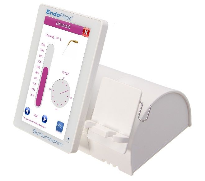
Pilot²
Illustration 5

Illustration 6

Illustration 7    7a    7b

Illustration 8

Illustration 9 Ill.10        Ill.11    Illustration 12   12a   12d 12b

Illustration 13

Illustration 14

                                      12c

Illustration 15

                                      -4-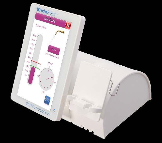
Pilot²
Description of the single parts

                                                                                                              EN
 ill.   Ref. No.         Designation                                                                   #
                        Control unit with a touch screen, including 5 connecting
   1     110 2011                                                                                      A2
                        sockets and a microSD slot (1a to 1f)

                        Power supply with primary plug, 2 models available
   2       110 2203                                                                                    A2
                        Input: 100 – 240 V AC Output: 12 V DC 1.50 A

   3     109 2361       Wireless foot switch, single pedal with Bluetooth                              A2

         109 2311       Apex cable set (from version v06 on)
                        consisting of:                                                                 A2
         109 2312       4a – Measuring cable with plug                                                 A1
         109 2314       4b – Lip-clip                                                                  A1
         109 2318       4c – Cap for the plug socket (for Lip-clip)                                    A1
         109 2315       4d – Cable for file clamp                                                      A1
         109 2316       4e – File clamp (can be dismantled)

   4                    The file clamp can be dismantled (see ill. 4e).
                        To dismantle, the contact is unscrewed and removed from
                        the knob. You can clean all parts individually (see
                        reprocessing instructions).
                        At the end of assembly, firmly tighten the contact again.
                        Caution: Check if the device is functioning properly! Loose
                        parts may fall out and enter the patient's mouth.

         110 2303       4f - Retainer for apex cable (mounted on the device)                           A1
                        Contra-angle for apex measurement. Fully insulated,
   5     109 0126                                                                                      A3
                        1:1 gear, with ISO-E coupling

                        Motor with apex measuring contact,
   6     109 0112                                                                                      A2
                        LED power indicator and ISO-E connection
         109 0151       DownPack (D-Pack) handpiece with LED indicator                                 A2
                        for processing removable parts:
   7
         540 5173       7a – Screw cap                                                                 A1
         364 2901       7b – Blue O-ring                                                               A1
         109 0152       D-Pack heating tips
   8                                                                                                   A4
         to ...56       Available in 5 different sizes

   9     823-616        Nut for BackFill-Needles                         (Order-no.110 1042)           A5

         823-620        BackFill Needles 20 ga (5 pcs)                   (Order-no.110 1044)
  10                                                                                                   A5
         823-623        BackFill Needles 23 ga (5 pcs)                   (Order-no.110 1045)
         823-635        BackFill Needles 25 ga (5 pcs)                   (Order-no.110 1046)

                        Thermal protector (4 pcs.)               (Order-no.110 1043)
  11     823-815                                                                                       A5
                        Heat insulator protects against thermal damage

Doc. No. 610 2222 v06                        -5-         (*applicable with the ultrasonic extension module)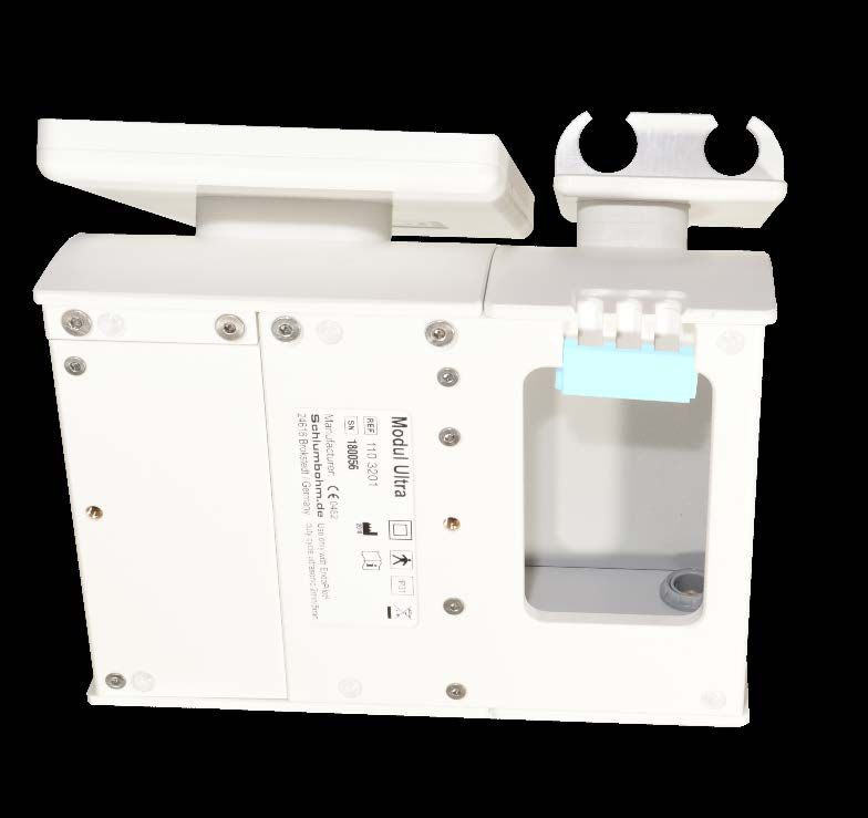
Pilot²
ill.   Ref. No.       Designation                                                      #
                     BackFill gun
 12    110 1041      12a - Release knob, 12b - Piston,                                 A5
                     12c - Lever and 12d - Guide cylinder with rotary knob
                     Tool for shaping and for screwing on and unscrewing the
 13    109 0147                                                                        A4
                     BackFill needles

                     Gutta-percha pellets for the BackFill gun
 14    109 0142                                                                        (-)
                     Gutta-percha bar contains 100 pellets

                     Cleaning set
 15    109 0148                                                                        (-)
                     2 brushes to clean the BackFill gun
       (#) refers to the relevant preparation instructions A1-A5, see chapter 18
       (-) means: The manufacturer has not foreseen any preparation for the product.

                                          -6-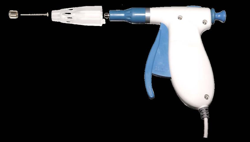
Pilot²
Ultrasonic extension module*

                                                                                                           EN
Illustration 16     EndoPilot² with ultrasonic module

Description of the single parts
 ill.   Ref. No          Designation                                                                #

  16     110 3201       Ultrasonic module with 1 connecting socket (15a)                            A2

                        Ultrasonic handpiece with Satelec® compatible screw thread
  17     X12282                                                                                     A6
                        Type: Acteon Satelec Suprasson        (Order-no. 109 3102)
                        Rinsing adapter Attachment for the standard syringe to clean
  18     109 3132                                                                                   A1
                        the ultrasonic handpiece
                        Wrench
  19     109 3113                                                                                   A6
                        Universal wrench for ultrasonic tips
                        Ultrasonic handpiece cable
  20     109 3122                                                                                   A6
                        Highly flexible supply cable with a handpiece plug

                        Twin wireless foot switch
         109 2351
                        Pedal I = Start
  21     Optional                                                                                   A2
                        Pedal II = Select / to select the functions,
                        including 2x 1.5 V batteries, type AA

        (#) refers to the relevant processing instructions A1-A5, see chapter 18

Doc. No. 610 2222 v06                        -7-      (*applicable with the ultrasonic extension module)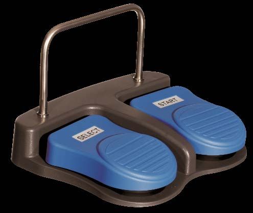
Pilot²

                                                                  cable guide for
                                                                  motor-, apex- and
                                                                  ultrasonic-cable

                                                                  (a locking clamp keeps
                                                                   the cables in place)

Illustration 16a
Ultrasonic module
Bottom compartment with the connection for the ultrasonic cable

Illustration 17                                       Illustration 18        Illustration 19
                                                     Rinsing sleeve
                                                      (for cleaning)

Illustration 20                                       lllustration 21

                                          -8-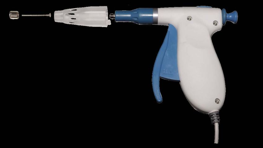
Pilot²
     Congratulations!

                                                                                                        EN
We are delighted you have decided to purchase the EndoPilot². You have made a good
choice. The family-owned company Schlumbohm® has been successful on the dental
industry market for 50 years. These many years of experience, as well as excellent contacts
to specialists, nationally and internationally, allow Schlumbohm® to design outstanding
devices that enable both the patient and the dentist to achieve an optimal treatment result.
In addition to striving, of course, for an optimal treatment result, the focus for each
development is on an easy and most convenient handling.
With EndoPilot², you have acquired a product which has been developed and tested with
the utmost care. The device meets the highest demands with regard to function and operation.

Caution! The device is available in various configuration levels

The EDP² has different functions depending on the configuration level:

•    EDP² comfort:       Endo motor with apex locator
•    EDP² plus:          Endo motor with apex locator, DownPack and BackFill
•    EDP² ultra:         Endo motor with apex locator and ultrasonic extension
•    EDP² ultra plus:    Endo motor with apex locator, DownPack, BackFill, ultrasound

All variants can be configured with a pump (liquid feed for the ultrasonic handpiece or SAF
system). This user manual describes the basic devices EndoPilot², EndoPilot² plus and
EndoPilot² ultra. All additional functions of the “Ultrasonic extension” add-on module are
marked separately with *.

Manufacturer information:
Schlumbohm GmbH & Co. KG                              Telephone: +49-4324 - 8929 - 0
Klein Floyen 8-10                                     Telefax:   +49-4324 - 8929 - 29
D-24616 Brokstedt                                     post@schlumbohm.de
Germany                                               www.schlumbohm.de

WEEE reg. no. DE 88116129

The manufacturer reserves the right to change the information and data contained in this
user manual without prior notice.
This user manual has been prepared with the greatest possible care. However, as errors can
never be fully excluded, we would appreciate any information at any time so we can improve
the documentation for you. Please contact us directly in such an event. Also, should you have
any further questions, please do not hesitate to contact us.

Doc. No. 610 2222 v06                      -9-     (*applicable with the ultrasonic extension module)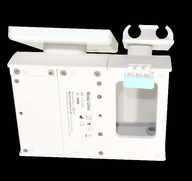
Pilot²
Table of contents......................................................................................................................... Page
1.          Notes ............................................................................................................................11
1.1.        Symbols used ........................................................................................................................... 11
1.2.        Intended use ............................................................................................................................. 13
1.2.1.      Apex locator ................................................................................................................ 13
1.2.2.      Motor ........................................................................................................................... 13
1.2.3.      DownPack handpiece with heating tip.......................................................................... 13
1.2.4.      BackFill gun ................................................................................................................. 13
1.2.5.      Ultrasonic handpiece* .................................................................................................. 13
1.3.        General precautions ................................................................................................................. 13
1.3.1.      Contraindications ......................................................................................................... 14
1.3.2.      Operating instructions .................................................................................................. 14
2.          First steps .................................................................................................................... 16
2.1.        Assembly ................................................................................................................................... 16
2.2.        Holders for the handpieces ..................................................................................................... 17
2.3.        Connection ................................................................................................................................ 17
2.4.        Touch display ............................................................................................................................ 17
2.5.        Foot switch ................................................................................................................................ 18
2.6.        Charging, switching-on, standby mode, switching-off ......................................................... 19
2.7.        Preparation of dental canal - Motor and contra-angle handpiece ...................................... 19
2.8.        Filling technique - DownPack (D-Pack) ................................................................................. 20
2.9.        Filling technique - BackFill....................................................................................................... 21
3.          Manual apex length determination ............................................................................... 22
3.1.        Tips for length determination................................................................................................... 23
4.          Motor system ............................................................................................................... 24
4.1.        Favorites .................................................................................................................................... 24
4.2.        Selection of the file systems ................................................................................................... 24
4.3.        Preparation ................................................................................................................................ 25
4.4.        MyFile file system ..................................................................................................................... 25
4.5.        Setup motor............................................................................................................................... 26
4.5.1.      File data ...................................................................................................................... 26
4.5.2.      Reciprocal function operating mode............................................................................. 27
4.5.3.      Apex functions during motor operation......................................................................... 28
4.5.4.      Calibrate ...................................................................................................................... 29
5.          Obturation ................................................................................................................... 30
5.1.        DownPack ................................................................................................................................. 30
5.2.        BackFill ...................................................................................................................................... 30
6.          Ultrasonic function*...................................................................................................... 31
6.1.        Operating instructions* ............................................................................................................ 31
6.2.        Setting the ultrasonic power output* ...................................................................................... 32
6.3.        Ultrasonic instrument selection* ............................................................................................. 32
6.4.        Setting the run time*................................................................................................................. 32
7.          Software release and updates ..................................................................................... 33
8.          Brightness / Volume..................................................................................................... 33
9.          Setting the language.................................................................................................... 33
10.         Auto-off time ................................................................................................................ 33
11.         Service information / Bluetooth .................................................................................... 33
12.         Maintenance, transport and disposal ........................................................................... 34
12.1.       periodical tests .......................................................................................................................... 34
12.2.       Maintenance.............................................................................................................................. 35
12.3.       Transport ................................................................................................................................... 35
12.4.       Disposal ..................................................................................................................................... 36
13.         Troubleshooting ........................................................................................................... 37
14.         Error messages ........................................................................................................... 39
15.         Warranty / Liability ....................................................................................................... 39
16.         Technical Data ............................................................................................................. 40
17.         EMC manufacturer's declaration .................................................................................. 41
18.         Cleaning, disinfection sterilization (Processing) ......................................................... 44

                                                                            - 10 -
Pilot²
1. Notes
EN
1.1. Symbols used
Description of the symbols used.
Symbol Description
The product complies with the requirements of the EU
Warning notice: Consult the accompanying documents!
Failure to comply with these instructions during operation may lead to
damage of the device or injury of the user or patient.
Special protection against electric shock (applied part)
This medical device must not be disposed of with normal garbage. The
national disposal regulations for waste electrical and electronic
equipment must be observed.
WEEE Directive (Directive 2002/96/EC)
Single-use product
Contains gutta-percha
Non-sterile
A medical device not subjected to sterilization
Contains silver
Date of expiry
EU authorized representative
automated processing in the thermal disinfector
Steam sterilization
Production lot
Manufacturer / Date of production
2021
Doc. No. 610 2222 v06 - 11 - (*applicable with the ultrasonic extension module)Pilot²
IP31 Protection against particles with 2.5 mm diameter and dripping water
Catalogue Number
Indicates catalogue number, part number of device
Serial number of the device or the components
Consult Instructions for Use
The device contains a lithium-ion battery (power output 48 Wh)
(The current shipping instructions must be followed during shipping!)
48 Wh
Class II equipment
To identify a class II insolation protection, complying with IEC 60601-1
China RoHS label for export to China
Wireless connection via Bluetooth
Fragile, handle with care
Indicates a medical device that can be broken or damaged if not handled carefully.
Different values on the outer package and on the device !
Package: Note temperature during storage / transport (-15°C to +60°C)
Device sticker: Note temperature during operation (+15°C to +40°C)
Keep Dry
Indicates a medical device that needs to be protected from moisture.
Humidity limitation
Relative humidity range for storage (on package) or use (on device)
Store the packaging in an upright position
Medical Device
This item is a medical-device
UDI of the device, Data-Matrix-Code (GS1-Code)
Read the user manual and processing instructions
Prescription Use Only
Caution: Federal (U.S.) law restricts this device to sale by or on the order of a physician.
No standard; designated by FDA per 21 CFR 801.109(b)(1)
- 12 -Pilot²
EN
1.2. Intended use
The EndoPilot² is a device for mechanical root canal treatment. It is intended exclusively for
use in dentistry and must not be combined with other devices. The EndoPilot² was specially
developed for endodontics and is intended solely for use by medical specialized staff in
professional health care facilities.
The EndoPilot² is intended solely for the following use:
1.2.1. Apex locator
The apex locator determines the file position in the root canal. This length determination can
either be performed manually (without a motor) by using the file clamp, or during preparation
using the contra-angle (integrated length determination with a motor).
1.2.2. Motor
Mechanical root canal preparation in combination with the pre-programmed nickel-titanium
files with standard setting, with optional integrated length determination. The file
manufacturer’s current file-parameters should be used in principle.
1.2.3. DownPack handpiece with heating tip
Vertical thermoplastic condensation of gutta-percha in the root canal and the cutting off of
gutta-percha pins.
1.2.4. BackFill gun
Final thermoplastic filling of root canals with gutta-percha.
1.2.5. Ultrasonic handpiece*
*Ultrasonic module: The ultrasonic extension has been developed as an add-on module for
the EndoPilot². It supplements the device concept with the ultrasonic function for the
execution of professional endodontic treatments.
Possible areas of application: Activation of a rinsing solution in the root canal, revisions,
preparations of the canal with ultrasonic instruments and the removal of pins.
1.3. General precautions
Read through this user manual carefully and completely! This is the only way to guarantee
maximum safety. The most common problems during operation and maintenance result from
the fact that insufficient attention is paid to basic safety precautions and possible accident
risks are not foreseen.
The user and team must be familiar with the device prior to the first usage.
Keep the user manual and the attachments (e.g. reprocessing instructions) on the device.
Always use a cofferdam to prevent the inhalation or swallowing of small parts and the
transmission of germs! If you have any questions or information on any problems, please
contact your dealer immediately. Do not use the device if the patient or the user has an active
implant (pacemaker, etc.)!
Doc. No. 610 2222 v06 - 13 - (*applicable with the ultrasonic extension module)Pilot²
*Ultrasonic module: Use safety goggles. The patient should also wear safety goggles. The
use of ultrasound may release aerosols and germs into the air. You must therefore always
use a surgical mask.
1.3.1. Contraindications
The application of gutta-percha in combination with the treatment of patients with a known
allergy to latex, silver or copper may result in allergic reactions. These allergic reactions can
manifest in irritations of the eyes, lips and face. Breathing difficulties may also occur. Patients
should be instructed to report any complaints immediately.
1.3.2. Operating instructions
Use
• The EndoPilot² may only be used by licensed specialists.
• The applied parts must be used sterile. It is imperative that you follow the
disinfection and reprocessing instructions (see chapter 18).
• Check the device for damage before use.
• Only use the device for its intended application.
• Do not combine the device with other devices, such as endo devices from other
manufacturers.
• Do not modify the product’s characteristics in any way. Schlumbohm® declines any
and all responsibility in the event of device modification.
• The microSD card must be removed from the EndoPilot² when shipping!
Removing this will switch off the power to the device.
Conditions of the location
• The device must not come into contact with liquids or be installed in damp places.
Keep the foot switch away from spilled liquids.
• Do not expose the device to direct or indirect heat sources.
• The device may not be used in an environment with free oxygen, explosive or
inflammable gases or flammable liquids.
• The EndoPilot² should not be installed near devices emitting electromagnetic
radiation so as not influence the correct length determination. Switch off mobile
phones in the immediate vicinity during treatment.
• Do not cover the device with cloths or foils. Flammable materials may be damaged
or even ignited if the DownPack function is activated unintentionally.
• Ensure that the rooms in which the device is used are equipped with smoke
detectors. National fire protection regulations must be adhered to.
• Never leave the appliance unattended when in use.
• Ensure that the foot switch cannot be pressed unintentionally, for example by a chair
or trolley.
• The signal of the wireless foot switch is transmitted in an encrypted form. This
technology ensures a secure connection between the foot switch and the device.
This prevents unintentional operation of one device with the foot switch of another
device. Do not operate mobile phones or devices with strong electromagnetic
- 14 -Pilot²
radiation in the immediate vicinity of the device. This may impair the wireless foot
EN
switch’s function in individual cases.
• The device does not contain any life-supporting functions. The continued
application in the event of device failure will likely be impossible. This failure will not
endanger the patient’s life. Make sure that the treatment can also be completed in
the event of device failure.
Device components and accessories
• The power supply has a safety-relevant function. Only use the supplied, medically
approved, original power supply unit!
• Follow the file manufacturer’s instructions for use and disposal of the endodontic
files.
• The accuracy of the length determination, the torque and the speed are only
guaranteed when using the EndoPilot 1:1 contra-angle.
• An exact length determination may not always be possible due to abnormal or
unusual canal morphology (blocked or fractured canal).
• The tolerance for torque and speed is 10%.
• The DownPack handpiece and BackFill gun become hot. There is a risk of burning,
damage to the environment and fire.
• Place the DownPack handpiece and the BackFill gun back into the holder
immediately after use.
• Only place the BackFill gun's thermal protector on the gun immediately before use
in the mouth, as this keeps it cool. Remove the thermal protector from the hot gun
after use.
• To avoid the leading-in of external voltages, the handpieces and the lip clip must
not be put down on electrically conductive surfaces.
• Always remove the lip clip from the patient's mouth when the apex measurement is
not required. The lip clip must not be in the patient's mouth when using ultrasound,
BackFill or DownPack. Never place the lip clip, file clamp and motor on conductive
surfaces. Always return the motor to the handpiece holder. Always place the lip clip
on the retaining provided for this purpose.
• Ensure that the file clamp of the apex cable has been put together correctly after
preparation and that the contact has been screwed-in tightly.
• Gutta-percha is a natural rubber which may cause allergic reactions (latex cross
allergy).
• *Ultrasonic module: Do not use any deformed or worn instruments. At first, always
choose a very low ultrasonic power output and only increase the energy when
necessary. The ultrasonic device is intended for intermittent (interrupted)
operation. To keep heating to a minimum, operation should be limited to 1 minute
at maximum power and to 4 minutes at minimum power.
• *Ultrasonic module: Please note that the ultrasonic instruments heat up during
operation. Make sure, therefore, that there is appropriate external cooling, if
necessary.
Compatibility
• Endo files: You can use all commercially available nickel titanium files with a
standard ISO shaft. The values for speed, torque and operating mode specified by
the respective manufacturer must be adhered to. Since the instrument
manufacturers reserve the right to make changes to the file parameters, the set
Doc. No. 610 2222 v06 - 15 - (*applicable with the ultrasonic extension module)Pilot²
values must be checked before operation to make sure that they correspond to the
current file manufacturer’s specifications.
• DownPack heating tips: Only use the original tips which are available from the
manufacturer.
• Backfill needles: Only use the original needles which are available from the
manufacturer.
• *Ultrasonic module: Ultrasonic tips: You can use commercially available
instruments with Satelec® threads (depending on your ultrasonic handpiece, also
EMS® compatible instruments).
General information
• Keep this user manual and all information safe on the device.
• Keep the documents for the entire product life cycle.
• The operator is obliged to report all incidents within the meaning of the current
regulations for medical devices in the EU, as well as any information on risks, to the
manufacturer.
2. First steps
2.1. Assembly
Please first compare the components delivered with the enclosed shipping documents and
the corresponding serial or LOT numbers. Check that the display glass is undamaged.
Please note that all components are supplied non-sterile and not disinfected (see
chapter 18).
The following conditions should be considered when installing the device:
• The support surface must be level and made of non-combustible material.
• The device must not be installed in damp places. Do not use the device
in areas when liquids have been spilt on the floor.
• Do not expose the device to direct or indirect heat sources. Direct sunlight must be
avoided.
• Only charge or operate the device when it is at room temperature (do not exceed
max. +40°C)!
• The ambient temperature must be within the prescribed limits.
(See chapter 16). Avoid heating up to above 60°C in any case!
• The device must not be installed near free oxygen, flammable gas mixtures or
liquids (e.g. in operating theatre or emergency areas).
• The EndoPilot² should not be installed near devices emitting electromagnetic
radiation so as not influence the correct length determination.
• Place the foot switch in such a way that it will be easy to operate.
• Make sure that the foot switch cannot be activated unintentionally.
• Place the device in such a way that the power supply cable can be pulled out of the
device when necessary.
- 16 -Pilot²
2.2. Holders for the handpieces
EN
The holders provide a safe position for the applied parts. Insert the retainer for the apex cable
laterally into the hole at right handpiece holder.
You can upgrade the device with additional functions (example: left arm with a holder for
DownPack and BackFill). For the assembly of additional holders as well as for the
arrangement of the handpieces, please follow the assembly instructions provided separately.
*Ultrasonic module: A double holder is mounted on the extension module for the ultrasonic
handpiece and the motor.
2.3. Connection
All connections are plugged in and must not be twisted! Care must be taken to ensure that
the plug’s groove fits into the socket’s groove. The ‘Push and Pull’ connections for the
handpieces are color-coded (the numbers refer to the illustrations on the inside cover page).
Figure Connection Use
1a blue Motor
1b green Apex cable, connection to the patient (lip clip)
1c black Power supply unit
1d Slot microSD card
1e red BackFill gun, optional
1f blue D-Pack, optional, please do not insert the motor here!
Insert the EndoPilot² microSD card into the SD slot before first use.
(Insert the card carefully, do not use sharp tools).
*Ultrasonic module: The ‘Push and Pull’ connections for the handpieces are color-coded as
for the EndoPilot²:
Figure Connection Use
16a grey Ultrasonic handpiece cable and ultrasonic handpiece
When connecting the ultrasonic handpiece to the ultrasonic cable, ensure that the handpiece
is not twisted during connection.
If the EndoPilot² control unit is not already equipped with the ultrasonic extension module in
the factory, this can also be done subsequent to the delivery. Your dealer will be happy to
advise you. An assembly instruction for this upgrade is available.
2.4. Touch display
Remove the transport protective film before use. All functions of the EndoPilot² are called up
using the convenient touch display. The touch display allows intuitive and self-explanatory
operation. Operate the touch display with a light touch of the finger. Operation is of course
possible when wearing gloves.
The display must not be operated with metallic objects under any circumstances (risk of glass
breakage)!
With the button, you will always return to the previous menu or back to the start menu.
Doc. No. 610 2222 v06 - 17 - (*applicable with the ultrasonic extension module)Pilot²
2.5. Foot switch
Functions of the wireless foot switch (single-pedal type Single):
• Starting / Stopping the motor
• Saving the actual measured root length (see chapter 3.)
• Activating the EndoPilot² from sleep mode
Additional functions of the optional two-pedal wireless foot switch (type Twin):
• Tapping on the Select button briefly:
Change to the next instrument.
• Pressing the Select button for a prolonged period:
Moving between the functions: Ultrasonic and endo motor.
To change the battery, please open the battery compartment under the foot switch’s base
plate. Remove the used batteries. Insert new batteries. Pay attention to the prescribed pole
direction. Correctly dispose of the old batteries.
Model: Location: Battery type:
Single foot switch Unscrew the base plate 2x 1.5 V, type AAA
Twin foot switch Battery compartment 2x 1.5 V, type AA
Do not use rechargeable batteries; they have a lower nominal voltage! Only use brand name
batteries and batteries of same type. Caution! If the wireless foot switch is not used for a long
time, the batteries must be removed.
Spare batteries should always be available for uninterrupted operation.
The wireless foot switch is already connected to the device on delivery.
If a new foot switch is supposed to be connected to the device, this is possible using the
service menu (see chapter 11).
- 18 -Pilot²
2.6. Charging, switching-on, standby mode, switching-off
EN
Make sure to fully charge the device before first use. (The device can only be charged or
switched on with the inserted microSD card.)
When charging, please ensure that the device has not been heated by sunlight. Charging is
interrupted at a device temperature above 40°C.
To charge, plug the power supply unit into the socket (the green LED in the power supply
unit must light up). The device plug of the power supply unit is plugged into the black socket
(1c) on the rear of the device. The device is switched on automatically by connecting the
power supply unit, the blue LED on the front of the device flashes during charging.
During charging, the display illumination can be switched off with the On/Off switch on the
rear of the device, charging continues. When the battery is fully charged, the blue LED lights
up continuously. The power supply can be disconnected.
The respective battery status is displayed at the bottom edge of the screen.
If the charge drops to 10% of the capacity, a warning message appears. In this case the
battery must be charged immediately. If not charged, the device will switch off to avoid a total
discharge of and damage to the battery.
Charge the battery regularly.
If the device is not used for a prolonged period of time, the device automatically switches to
sleep mode and the display illumination switches off. The sleep mode is indicated by slow
flashing of the blue LED in the display. By briefly pressing the foot switch or the touch display,
the device switches on again. The last menu used is displayed again.
After a long waiting period, the device will switch off completely. This "Auto off" time can be
set in the setup menu.
To avoid unnecessary power consumption in standby mode, the mains plug should be
removed from the plug socket when the EndoPilot² is not in use for a longer period of time.
In case of malfunctions, you can completely switch off the device by removing the microSD
card. The microSD card must be removed when the device is shipped.
2.7. Preparation of dental canal - Motor and contra-angle handpiece
The EndoPilot² contra-angle (5) is attached to the motor (6). Only use contra-angles with a
1:1 ratio. The integrated apex length determination during preparation (see chapter 4.5.3)
only works in conjunction with the original EndoPilot² contra-angle.
If the contra-angle handpiece was changed or sterilized, a calibration must be performed
under the C a l i b r a t i o n (motor menu) menu item. The calibration compensates the friction
in the contra-angle.
Contra-angles may only be changed when the motor is at a standstill.
Operating instructions:
Before operation, check that the motor is firmly locked in place in the contra-angle.
During operation of the contra-angle, never exert pressure on its push button, as this could
lead to friction or incorrect measurements!
Doc. No. 610 2222 v06 - 19 - (*applicable with the ultrasonic extension module)Pilot²
Due to the shape of the root canal, the endo files are bent and stressed during use. Although
the device reduces the risk of file breakage, file breakage cannot be completely eliminated.
Please make sure that you know the instruments’ permissible torques. Choose the right file.
Never use deformed or damaged files!
The menu offers a variety of setting options. All parameters such as speed, torque and
operating mode etc. may be changed individually.
Parameters that deviate from the instrument manufacturer’s specifications may lead to file
breakage and other damage. Schlumbohm® is not liable for damage caused by operating the
device in a way that deviates from the instrument manufacturer’s specifications.
To avoid file breakage, please note the following points:
• Never apply pressure to insert the file or to move it forward.
• Even Nickel-titanium files break due to material fatigue. Only prepare as many canals as
intended by the file manufacturer.
• Experience and practice are indispensable for the effective use of NiTi instruments.
• Practice handling extracted teeth or Endo plastic blocks.
LED motor: GREEN The torque is below 80% of the permissible load
RED The torque is above 80% of the permissible load
2.8. Filling technique - DownPack (D-Pack)
Connect the DownPack handpiece (7) to the blue socket (1f) on the left side of the EndoPilot².
Only use the handpiece holder provided on the EndoPilot² for storage.
Note that the tip becomes very hot. It can reach a surface temperature of over 400°C without
a thermal load (without heating up the gutta-percha).
Do not use the tip in the air, without thermal load (without cooling)
Do not press the foot-switch several times repeatedly (pumping).
Using the heating tip:
Open the chuck by two turns of the screw-cap and insert the heating tip (8) (always insert
the shaft as far as possible). Fix the tip by tightening the screw-cap. Before use, check that
the heating tip is fixed firmly in position. A twisting tip may lead to injuries. You can use the
wrench (13) to loosen the screw-cap when necessary. Note the limited service life of the
heating tip. This varies depending on the frequency of use, load and deformation in each
case. Check the heating tip for function and mechanical integrity before each use. The use
of excessive force may lead to breakage and to injuries due to slipping.
Never use heating tips from other manufacturers!
Do not use the DownPack handpiece with the apex cable at the same time.
It is possible to heat up the tooth and the adjacent tissue by continuously introducing heat
into the treatment site. Ensure adequate waiting times and proceed with caution. Excessive
heating may lead to changes in the filling material’s properties.
LED DownPack:
Red light: DownPack is in operation, the heating process is running
(for application see chapter 5.1).
- 20 -Pilot²
2.9. Filling technique - BackFill
EN
Connect the BackFill gun (12) with the cable to the red socket (1f) of the device. The nut for
BackFill needle (9) must be tightened with the wrench (13) to avoid leakage of gutta-percha
at the thread. Form the needle with the tool’s forming rollers. Always make sure that the
needle is not bent or torn out of the connection base. Avoid bending back and forth. Press
the release (12a) and pull the piston (12b) backwards a little. Then insert only 1 pellet of
gutta-percha (14) into the upper opening of the gun for the time being. If the gun is already
heated, this should be done quickly to prevent the inserted material from sticking. Use the
lever (12c) to push the gutta-percha into the heating chamber with the help of the piston (12b)
and later through the needle. Make sure that the small screw and the seal at the end of the
piston (12b) are in place and firmly tightened. As long as the set temperature is not reached
and the gutta-percha is still hard, you should not press too hard to avoid damaging the gun.
If the heating times are longer, the gun’s outer parts will also be warmed up.
The bushing in the front area of the gun reaches temperatures of over 200°C. This is
necessary as a matter of principle, but requires careful handling.
Always use a heat thermal protector (11) to avoid burns. Always put on the thermal protector
shortly before application so that it does not heat up. Remove the thermal protector from the
gun after applying the gutta-percha. If necessary, change the protector during work to have
a cool thermal protector on the gun in each case. Check the heat of the thermal protector
(11) with your fingers before the application.
Do not touch the patient's lips or mucous membrane with the needle. During the filling
process, the needle should rise with the filling material.
Do not place the BackFill gun on electrically conductive surfaces. External voltages could be
transferred. Do not use the BackFill gun with the apex cable at the same time. Only use the
EndoPilot² holder for storage.
The use of excessive force may lead to breakage of the needle and to injuries. Always make
sure that the gun has been cleaned and prepared before each treatment. Use a new needle
in each case and a new gutta-percha pellet for each application.
After application, squeeze out any gutta-percha residue from the gun while the handpiece is
still hot. First unscrew the needle and pull the piston backwards out of the gun.
Only use original gutta-percha pellets. For information on dismantling, see the reprocessing
instructions.
Doc. No. 610 2222 v06 - 21 - (*applicable with the ultrasonic extension module)Pilot²
3. - 6. Functions Start menu
Setup button (see chapter 7)
3. Manual apex length determination
4. Motor system for NiTi files
5. BackFill gun DownPack handpiece
6. Ultrasonic function
Battery status display
3. Manual apex length determination
In this menu you can pre-probe the canal manually, i.e.
with a file guided by the hand. Use the lip clip (4b) and the
file clamp (4e) for this.
The marker (horizontal line) determines the position in the
root canal where the ‘Auto-Stop’ function is reached
during mechanical preparation. The manufacturer has
already set the marker. The user (if desired) can, however,
change the setting directly on the display by moving the
bar (by tapping on it with the finger). With this function it is
possible to transfer the X-ray verified position of a pilot
instrument to the display.
The marker’s setting remains unchanged until the device
is switched off. If the device is switched on again, the line
is reset to the default value.
Do not place the measuring cables on electrically
conductive surfaces, as external voltages could be
transferred to the device.
Use the button to access the settings in the Apex setup menu.
- 22 -Pilot²
EN
You can configure the settings in this Setup menu:
For example, you can set different sounds and the
volume.
Caution:
If you allow the file to touch the lip clip, this will cause a
short circuit. With this short circuit you can test the correct
operation of the display and apex locator.
3.1. Tips for length determination
Place the cap (4c) on the lip clip’s socket before use; the cap protects the socket from
contamination.
The lip clip (4b) is hung in the patient's cheek pouch on the opposite side of the tooth to be
treated.
Remove the lip clip from the patient's mouth if you do not need the measurement (especially
if you use other functions such as ultrasound or BackFill or DownPack).
Before you start the length determination, the canal should be rinsed briefly with physiological
saline solution. The canal input must then be dried (e.g. with a cotton pellet) to avoid leakage
current and, as a consequence, incorrect measurements. Protective gloves should be worn
during the length determination so that the measuring current has no power dissipation. For
the manual measurement, the file is connected to the file clamp below the shaft and slowly
inserted into the root canal.
The file is automatically connected using the contra-angle for the integrated length
determination during preparation. Here, the file clamp is not required.
Please keep in mind that incorrect measurements due to disturbances (conductive residual
fillings, cracks, etc.) may occur during the electronic length determination as a matter of
principle.
Chemicals in the canal can influence the measurement due to different conductivity. The ideal
measuring medium is physiological saline solution.
The results should always be compared with an X-ray control image.
Doc. No. 610 2222 v06 - 23 - (*applicable with the ultrasonic extension module)Pilot²
4. Motor system
4.1. Favorites
When you access the Preparation menu, the Favorites
menu will appear.
The device has a large file database.
The values of many file systems are already stored in this
database.
Use the F i l e s y s t e m s button to reach the Selection
menu (see 4.2).
After activation, the file systems that are saved as favorites
are displayed here. This will speed up the selection of the
file system in the future.
This example shows F360 and F6 SkyTaper.
The MyFile system is initially an empty system.
Here, the user can create his or her own sequences by
copying files. See chapter 4.4
4.2. Selection of the file systems
Select the file systems to be displayed in the Favorites
menu. You can choose a maximum of 5 systems.
Here, you can find further file systems
- 24 -Pilot²
4.3. Preparation
EN
After selecting the file system and the desired file, the Endomotor is started up using the foot
switch in the Preparation menu. The selected file appears in the upper line. The speed and
torque values of the file are indicated below.
In addition to the currently selected file, further files are
shown. You can select these by tapping on or swiping
them directly.
Press the button to call up ‘Setup Motor’ (see 4.5).
Here, you can configure the settings for the motor drive.
Changed values are displayed with a red exclamation
mark.
The apex display is always in operation and thus also
allows manual probing with the help of the file clamp.
Please note that the file clamp must be stored in an
insulated place. Otherwise, incorrect measurements may
occur during the length determination using the contra-
angle handpiece.
*By pressing the ultrasonic- icon you can switch to the
ultrasonic-menu
(if the ultrasonic-extension-module is mounted).
You can switch the integrated apex measurement off and on again during preparation by
pressing the green apex icon at the right edge of the screen.
4.4. MyFile file system
The MyFile system offers 5 sequences for free
configuration. Select one of the ‘MySequence’ sequences
from the menu (sequence 1 has been chosen here).
Sequences that have not yet been filled are displayed in
grey.
Now copy up to 10 instruments from existing file systems
into the sequence in any order.
To copy, press the green plus button at the desired position
and select a file.
You can change the file parameters (speed, torque...) of the
files copied into the MyFile file system as desired.
These changes have no repercussions on the data in the
original file system.
You can delete entries again with the Minus button
Doc. No. 610 2222 v06 - 25 - (*applicable with the ultrasonic extension module)Pilot²
4.5. Setup motor
The settings that apply to the entire preparation are
chosen under this menu.
It is possible to individually change the selected file’s
parameters. Select the F i l e d a t a . The File setup opens
(see below).
You can configure further settings for the apex
measurement during motor operation under A p e x
setup.
You can test the motor with the contra-angle handpiece
under C a l i b r a t e . Leave the motor and the contra-angle
handpiece in the holder and start the calibration.
4.5.1. File data
The File setup menu offers a variety of setting options. The device allows all parameters such
as speed, torque, operating mode, etc. to be changed individually. Parameters that differ from
the instrument manufacturer’s specifications may lead to file breakage and other damage.
Under the Movement menu item, you can select:
• Twist (right rotation with ‘Shake loose’ when jamming)
• Twist off (right movement, motor stops in the event of
overload)
• Left rotation
• Reciprocal function
Note:
Please keep in mind that the file manufacturers reserve
the right to make changes and customizations to the
instrument’s characteristic values. The data stored in this
device has been defined with great care in accordance
with manufacturer recommendations. The user can
individually customize future changes or import such
changes via an update.
- 26 -Pilot²
4.5.2. Reciprocal function operating mode
EN
General:
An Endo instrument is set into a cyclic right-left movement with the reciprocal technique,
which was already known in the 1980s as the balanced force technique. The user
rhythmically pulls the instrument out of the canal to remove chips. The advantage of this
technique is the significant saving of time.
Often, less files than usual are used for the preparation. In practice, both NiTi instruments,
that were originally only intended for fully rotating use, and special instruments that were
specially developed for the reciprocal operation, are currently being used.
Unlike the well-known unchangeable devices, the EndoPilot² offers a free selection of
parameters. The user can individually customize the instrument’s movement parameters.
Since no file manufacturer data has been published at present, the user must define the
parameters suitable for him or her and his or her file system. Specifically, this can be done
for testing purposes during the sample preparation of training blocks. The pre-set values
should always be customized.
It has to be pointed out that experience and training are necessary for this technique.
The user should gain experience on extracted teeth. It has to be assumed that the use of
different file systems will lead to different results. To avoid warping or distorting the file, the
same values should be set for the left and right rotation. The pause-time offers an intermittent
operation and reduces the file’s pulse load.
Configuring the settings and the application:
Under the F i l e s y s t e m s overview, the device offers the
R e c i p r o c a l file system (see chapter 4.1). It is
representative of file systems that are to be operated in
reciprocal mode. The user must still customize the pre-
set values (to configure the settings see below). It is
possible to select the reciprocal function for each file from
the other pre-programmed file systems that were actually
designed for full rotation. Select the function in the File
Setup menu of the respective file under M o v e m e n t .
The parameters are set using the - or + button and
saved with S a v e .
During your work, please ensure a constant removal of
chips.
Doc. No. 610 2222 v06 - 27 - (*applicable with the ultrasonic extension module)Pilot²
Remark:
The torque is also monitored in this operating mode. However, since this technique does not
have a distinct start-up phase when the motor is started, the torque control can already be
triggered at high speed settings when the motor is started. In this case, a higher torque limit
should be set.
The cyclic drive.
This function provides a step-by-step drive in the direction of rotation. To configure this
function, a L e f t or R i g h t parameter is set to zero. The other parameter indicates the length
of the step. The pause between the movements allows the instrument to partially reset the
torsion.
4.5.3. Apex functions during motor operation
You can select the settings that apply to the preparation
under the A p e x s e t u p menu.
(See also section chapter 3)
You can set various sounds and the apex signal’s
volume.
Here, you define how the motor reacts when reaching the
apex position.
You can set the motor’s stop time. You can also switch off
the function for stopping the motor at the apex.
As Apex function you can select:
- Apex stop (stop time: 0.5 or 1 or 2 seconds)
- Apex stop off (the apex position is displayed, the
motor does not stop automatically).
Check the apex cable and the correct connection by briefly touching the lip clip with the
clamped file. The Short circuit error message must be displayed (see chapter 14). A
convenient function of the EndoPilot² is the length determination during the mechanical
preparation. In principle, all instructions already mentioned in chapter 3 (Manual apex length
determination) apply. For the measurement during preparation, the contra-angle handpiece
takes over the file clamp’s task. The measuring signal is transferred to the file through the
insulated contra-angle. The lip clip is still needed to close the electric circuit.
The results should always be compared with an X-ray control image.
- 28 -Pilot²
You can select a total of two modes of operation:
EN
1. Apex function A p e x s t o p 0.5 seconds/ 1 second/ 2 seconds.
The position or propulsion of the file in the root canal is displayed on the symbolized apex
during preparation and the manual probing. It is not possible to enter or change the
parameters while the motor is being started up using the foot switch.
1. If the horizontal line, which may have been set by manual probing, is reached, the motor
stops for the selected time unit (0.5; 1 or 2 seconds).
2. An acoustic signal and flashing red LED on the motor signal that, with immediate effect,
the file’s maximum torque limit will be further reduced in the cutting direction.
2. Apex function A p e x s t o p o f f
The position or propulsion of the file in the root canal is displayed on the apex image on the
display during preparation and the manual probing.
An acoustic signal sounds when the horizontal line is crossed. The motor does not stop and
the torque is not reduced either.
Note: An electronic length determination is only possible with conductive tool shafts. There
are instruments with insulating shafts. It is therefore not possible to determine the length
during preparation.
4.5.4. Calibrate
Always perform a calibration after each sterilization. The
calibration compensates for the contra-angle’s friction.
This calibration can compensate for small torque losses
at the contra-angle. This function always allows safe
operation at low torque limits.
If calibration is not possible, the contra-angle will be very
dirty or damaged. In this case, please contact the
manufacturer.
Doc. No. 610 2222 v06 - 29 - (*applicable with the ultrasonic extension module)Pilot²
5. Obturation
5.1 Setting the DownPack temperature
5.2. Setting the BackFill temperature
The temperatures shown are only examples.
Here, the remaining run time of the BackFill gun
is displayed.
5.1. DownPack
In this menu, you can select the temperature of the heating tip. The temperature column is
set to the desired temperature (touch display). Start the heating process by pressing the foot
switch. An acoustic signal sounds when the desired temperature is reached. Releasing the
foot switch (after a few seconds) will stop the heating process (second acoustic signal).
If you press the foot switch for a longer time, the heating process is automatically stopped
for safety reasons. The shut-off time depends on the chosen temperature. At maximum power,
the device stops after 5 seconds. At low power, the device stops after 40 seconds at the
latest.
Do not press several times in quick succession. This will make the needle hotter than desired.
During the heating process, the connected BackFill gun is switched off for a short time.
Please also refer to chapter 5.2.
5.2. BackFill
You can select the temperature of the gun’s heating in this menu. The BackFill gun must be
connected. The temperature column is set to the desired temperature using the touch display.
The device is heated as soon as a temperature has been chosen. The ‘Heating up’ message
appears. When the temperature is reached, an acoustic signal sounds and the auto-off time
of max. 15 minutes is displayed. After the time has elapsed, the heating process is
automatically switched off again (acoustic signal). You can switch off the heating process
manually by pressing the OFF button at the bottom of the temperature column.
Do not leave the device unattended during the BackFill operation.
During obturation (D-Pack and BackFill), the patient must no longer be connected to the apex
cable!
- 30 -Pilot²
6. Ultrasonic function*
EN
6.2 Setting of the ultrasonic power output
Select the power by pushing the bar graph
6.4 Ultrasonic instrument selection
Press the name of the tool to enter the
tool-library
6.4 Setting of the run time
Select the run time directly at the clock
With the motor button you will return
to the last used file system
6.1. Operating instructions*
When inserting the instruments, make sure that only instruments with a suitable type of
thread are used.
First tighten the selected instrument by hand and then with the wrench. When using fixed
wrenches, take care not to overtighten the instruments. The handpiece and the instrument
may be damaged. Only change the instruments when the ultrasonic handpiece is switched
off. Do not twist the handpiece’s cable connection. Do not use instruments that have been
deformed or show wear. Pay attention to the product life cycle of the instruments. Work
without exerting excessive pressure on the instruments. Instrument breakage may lead to
injuries. Dispose of used instruments in an appropriate manner. Ensure that a contamination
or an infection is prevented.
If possible, cool the instrument with external cooling to prevent it and the treatment site from
heating up. Always use sterile water when working in the root canal.
Please note that freely vibrating, thin instruments may also break without an external load,
which is solely due to the ultrasonic vibration. Flying splinters may lead to injuries. The device
may only be operated when the ultrasonic handpiece is connected to the handpiece cable.
Never touch the handpiece cable’s contacts! Select only appropriate program parameters for
the instrument. You must no longer used the device if malfunctions or disturbances occur.
Contact the manufacturer immediately.
Ensure that the ultrasonic tips are used according to your field of application. Do not use any
other ultrasonic handpieces or cables.
During the ultrasonic application, the patient must no longer be connected to the apex cable!
Place the handpieces back into the holder after use.
The handpiece connection of the ultrasonic handpiece to the cable and the internal contacts
must be absolutely dry. Pay attention to damage to the insulation and the handpiece. Only
use proper functioning handpieces and ultrasonic cables. Damaged insulation may lead to
electric shocks.
Doc. No. 610 2222 v06 - 31 - (*applicable with the ultrasonic extension module)You can also read