OWNER'S MANUAL MANUEL DU PROPRIÉTAIRE MANUAL DEL PROPIETARIO - Danby
←
→
Page content transcription
If your browser does not render page correctly, please read the page content below
OWNER’S MANUAL
                                                           MANUEL DU PROPRIÉTAIRE
                                                           MANUAL DEL PROPIETARIO

                                                                    DAS090BAHWDB
                                                                    DAS120BAHWDB
                                                                    DAS180BAHWDB
                                                                    DAS240BAHWDB

                SPLIT AIR CONDITIONER
                Installation Guide ............................................ 1 - 28

                CLIMATISEUR DIVISÉ
                Guide d’installation........................................... 29 - 56

                AIRE ACONDICIONADO DIVIDIDO
                Guía de instalación........................................... 57 - 84

   FOR ANY QUESTIONS OR CONCERNS REGARDING INSTALLATION OR SERVICING OF THIS UNIT,
               PLEASE CONTACT THE DEALER OR BUILDER WHO SOLD THE UNIT.
         _____________________________________________________________________

    POUR TOUTE QUESTION OU PRÉOCCUPATION CONCERNANT L’INSTALLATION OU L’ENTRETIEN
     DE CET APPAREIL, VEUILLEZ CONTACTER LE REVENDEUR OU LE CONSTRUCTEUR QUI A VENDU
                                          L’APPAREIL.
             __________________________________________________________________

   PARA CUALQUIER PREGUNTA O INQUIETUD RELACIONADA CON LA INSTALACIÓN O SERVICIO DE
  ESTA UNIDAD, PÓNGASE EN CONTACTO CON EL DISTRIBUIDOR O CONSTRUCTOR QUE VENDIÓ LA
                                       UNIDAD.

www.Danby.com        DANBY PRODUCTS LIMITED, ONTARIO, CANADA N1H 6Z9
                       DANBY PRODUCTS INC., FINDLAY, OHIO, USA 45840                      2019.12.13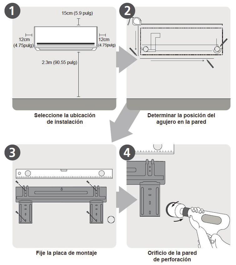
Important Safety Information
              READ AND FOLLOW ALL SAFETY INSTRUCTIONS
SAFETY PRECAUTIONS                                         • This appliance is not intended for use by persons
                                                             (including children) whose physical, sensory or
Incorrect installation due to ignoring instructions          metal capabilities may be different or reduced, or
can cause serious damage or injury.                          who lack experience or knowledge, unless such
                                                             persons receive supervision or training to operate
• When connecting refrigerant piping, do not let             the appliance by a person responsible for their
  substances or gases other than the specified                safety.
  refrigerant enter the lines as this will lower the       • Do not install the appliance in a location that
  unit’s capacity and can cause abnormally high              may be exposed to combustible gas leaks.
  pressure in the refrigeration system, which can            If combustible gas accumulates around the
  lead to explosion or injury.                               appliance, it may cause fire.
• Installation must be performed by a certified             • Do not operate this appliance in a wet room
  HVAC technician. Defective installation can                such as a bathroom or laundry room. Too
  cause water leakage, electrical shock or fire.              much exposure to water can cause electrical
• In North America, installation must be performed           components to short circuit.
  in accordance with the requirement of NEC and            • The appliance must be properly grounded or
  CEC by authorized personnel only.                          electric shock can occur.
• Contact an HVAC technician or the sales agent            • Install drainage piping according to the
  for information on repair or maintenance of this           instructions in this manual. Improper drainage
  appliance.                                                 may cause water damage.
• Only use the included accessories, parts and
  specified parts for installation. Using non-
  standard parts can cause water leakage,                  NOTE ABOUT FLUORINATED GASES
  electrical shock, fire and can cause the unit to
  fail.                                                    • This appliance contains fluorinated gasses. For
• Install the appliance in a firm location that can           specific information on the type and amount of
  support the unit’s weight. If the chosen location          gas, refer to the relevant label on the appliance
  cannot support the appliance’s weight, or if               itself.
  the installation is not completed properly, the          • Installation, service, maintenance and repair of
  appliance may fall and cause serious injury or             this appliance must be performed by a certified
  damage.                                                    HVAC technician.
• For all electrical work, follow all local and            • Uninstallation and recycling must be performed
  national wiring standards and regulations and              by a certified HVAC technician.
  this manual. You must use an independent circuit         • If the appliance has a leak detection system
  and single outlet to supply power. Do not connect          installed, it must be checked for leaks at least
  other appliances to the same outlet. Insufficient           every 12 months. When the appliance is
  electrical capacity or defects in electrical work          checked for leaks, proper record keeping of all
  can cause electrical shock or fire.                         checks is strongly recommended.
• For all electrical work, use all specified cables.
  Connect cables tightly and clamp them securely
  to prevent external forces from damaging the
  terminal. Improper electrical connections can
  overheat and cause electrical shock or fire.
• All wiring must be correctly arranged to ensure
  that the control board can close properly. If the
  control board cover is not closed properly, it
  can lead to corrosion and cause the connection
  points on the terminal to overheat, catch fire or
  cause electrical shock.
• In certain functional environments, such as
  kitchens, server rooms, etc., the use of specially
  designed air conditioning units is highly
  recommended.

                                   SAVE THESE INSTRUCTIONS!
                                                       1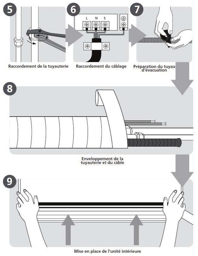
INSTALLATION INSTRUCTIONS

ACCESSORIES
The air conditioning system comes with the following accessories. Use all of the installation parts and
accessories to install the air conditioner. Improper installation may result in water leakage, electrical shock,
fire or may cause the equipment to fail.

                    Part                                       Image                            Quantity

Mounting plate                                                                                       1

Mounting plate fixing screw ST3.9 x 25                                                                5

Clip anchor                                                                                          5

Remote control                                                                                       1

Dry battery AAA.LR03                                                                                 2

Seal                                                                                                 1

Drain joint                                                                                          1

                                                        2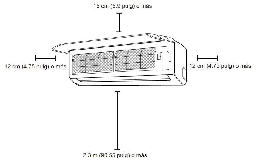
INSTALLATION INSTRUCTIONS

INSTALLATION SUMMARY - INDOOR UNIT

                                     Wall Mounting Plate

                   Front Panel
                                                                               Power Cable

        Louver
                                                                               Drainage Pipe

                      Functional Filter
                   On Front of Main Filter                                         Signal Cable
                                                                                   Refrigerant Pipe

                                                                     Remote Control

                                                                                  Outdoor Unit
                                                                                  Power Cable

Note: Illustrations in this manual are for explanatory purposes only. The actual shape of the appliance may
be slightly different. The actual shape shall prevail.

                                                      3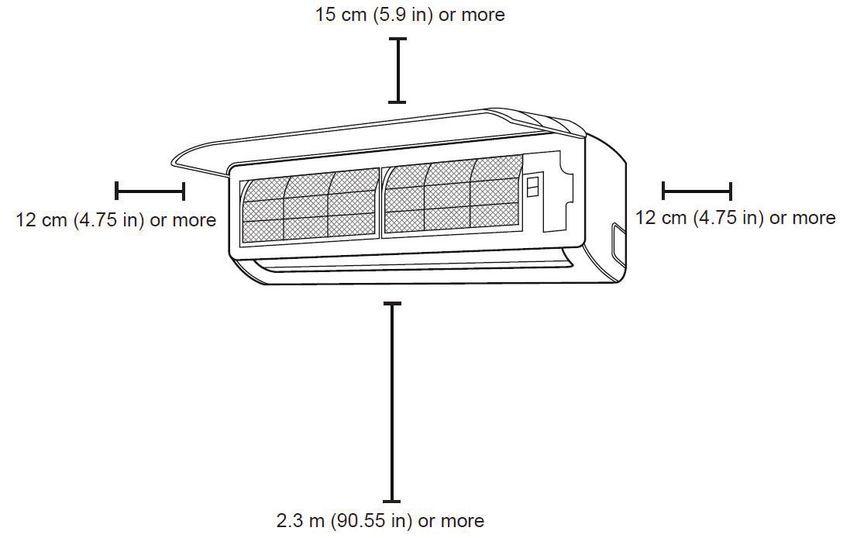
INSTALLATION INSTRUCTIONS

INSTALLATION SUMMARY - INDOOR UNIT

                                     4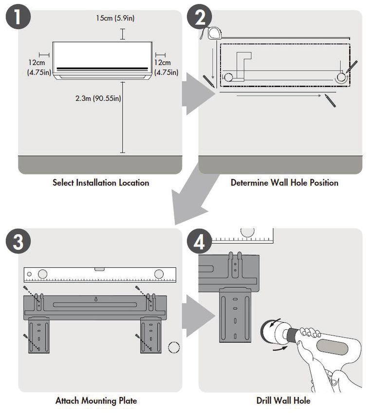
INSTALLATION INSTRUCTIONS

INSTALLATION SUMMARY - INDOOR UNIT

                                     5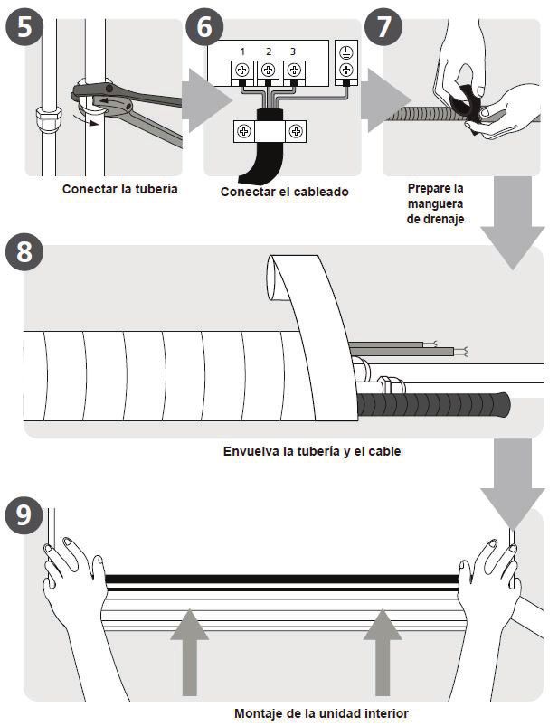
INSTALLATION INSTRUCTIONS

INDOOR UNIT INSTALLATION
Before installing the indoor unit, refer to the label on the product box to ensure that the model number on the
indoor unit matches the model number on the outdoor unit. The indoor unit model number will end with a “-I”
and the outdoor unit model number will end with a “-O”, otherwise they should be identical.

Step 1: Select Installation Location

Proper installation locations meet the following standards:

•   Good air circulation.
•   Convenient drainage.
•   Noise from the unit will not be disturbing.
•   Firm and solid location that will not vibrate.
•   Strong enough to support the weight of the unit.
•   At least 1 m (3 feet) away from all other electrical devices, such as televisions, radios and computers,
    which could impact the infrared remote signal.

Do not install the indoor unit in locations that have the following:

•   Near any source of heat, steam or combustible gas.
•   Near flammable items such as curtains or clothing.
•   Near any obstacle that might block air circulation.
•   Near any doorway.
•   In direct sunlight.

Refer to the below illustration to ensure proper distance from surrounding walls and ceiling:

                                                        6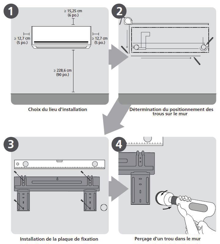
INSTALLATION INSTRUCTIONS
Step 2: Attach Mounting Plate To Wall
The mounting plate is the device that attaches the indoor unit on the wall.
1. Remove the screw that attaches the mounting plate to the back of the indoor unit.
2. Place the mounting plate against the wall in the location where the indoor unit will be installed.
3. Drill holes for the mounting screws, ensuring that the screws enter wall studs that can support the weight
of the unit.
4. Secure the mounting plate to the wall with the provided screws. Ensure that the mounting plate is flat
against the wall.
Note: If the wall is made of brick, concrete or similar material, drill 5 mm (0.2 in) diameter holes in the wall
and insert the provided sleeve anchors. Secure the mounting plate to the wall by tightening the screws into
the clip anchors.
Mounting Plate Dimensions
Different models have different mounting plates. To ensure
that there is ample room to mount the indoor unit, check
the diagrams below which show the two different types of
mounting plates along with the following dimensions:
• Width of mounting plate.
• Height of mounting plate.
• Width of indoor unit relative to mounting plate.
• Height of indoor unit relative to mounting plate.
• Recommended position of wall hole, both to the left and
right of the indoor unit.
• Relative distance between screw holes.
Model A 34.8 cm (13.7”)
Model B 40.1 cm (15.78”)
3.7 cm (1.45”)
17.9 cm (7.05”) 22.9 cm (9.01”)
4.2 cm (1.65”)
10.1 cm (4”) 22.8 cm (8.98”)
13.6 cm (5.35”) 12.6 cm (4.96”)
4.9 cm (1.95”)
29.7 cm (11.7”)
4.7 cm (1.85”)
29 cm (11.4”)
Indoor unit outline Indoor unit outline
4.9 cm (1.95”)
5.8 cm (2.28”)
Left rear wall Right rear wall Left rear wall Right rear wall
hole 6.5 cm (2.5in) 72.2 cm (28.45”) hole 6.5 cm (2.5”) hole 6.5 cm (2.5”) 80.2 cm (31.6”) hole 6.5 cm (2.5”)
Model C 51.7 cm (20.37”)
Model D
5.8 cm (2.3”)
57.8 cm (22.8”)
14.4 cm (5.65”)
13.8 cm (5.45”)
22.1 cm (8.7”) 29.8 cm (11.7”)
31.9 cm (12.55”)
5.7 cm (2.25”)
5.4 cm 7.9 cm(3.1”) 5.4 cm (2.1”)
Indoor unit outline (2.1”)
33.6 cm (13.2”)
14.9 cm Indoor unit outline
4.9 cm (1.9”)
4 cm (1.55”)
(5.9”)
Left rear wall
4.9 cm (1.9”)
hole 6.5 cm (2.5”) 3.4 cm (1.35”)
96.5 cm (38”) Left rear wall Right rear wall
Right rear wall 13.8 cm (5.4”) 14.9 cm (5.9”)
hole 6.5 cm (2.5”) 108 cm (42.5”) hole 6.5 cm (2.5”)
hole 6.5 cm (2.5”)
7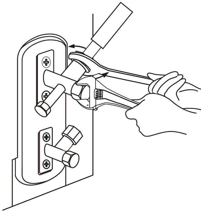
INSTALLATION INSTRUCTIONS

Step 3: Drill Wall Hole For Connective Piping

A hole must be drilled through the wall to the outside to accommodate the refrigerant piping, the drainage
pipe and the signal cable that will connect the indoor and outdoor units.

1. Determine the location of the wall hole based on the position of the mounting plate. See Step 2 for
   mounting plate dimensions.

2. The wall hole should have a 65 mm (2.5 in) diameter and it should be drilled on a downward angle to
   facilitate drainage. The outdoor end of the hole should be lower than the indoor end of the hole by 5 - 7
   mm (0.2 - 0.275 in).

3. Place the protective wall cuff in the hole. This will protect the edges of the hole and will help seal the
   hole once the installation is complete.

Note: When drilling the wall hole, make sure to avoid wires, plumbing and other sensitive components that
could be within the wall.

                                                        8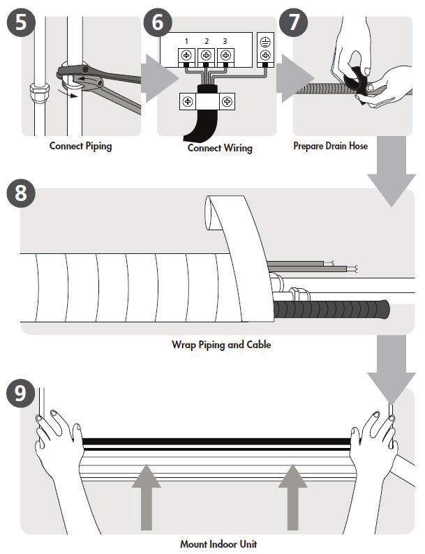
INSTALLATION INSTRUCTIONS

Step 4: Prepare Refrigerant Piping

The refrigerant piping is inside an insulating sleeve attached to the back of the
unit. The piping must be prepared before passing it through the hole in the wall.
Refer to the Refrigerant Piping Connection section for detailed instructions on
pipe flaring and flare torque requirements, etc.

1. Based on the position of the wall hole relative to the mounting plate, choose
   the side from which the piping will exit the unit.
                                                                                        Knock out panel
2. If the wall hole is behind the unit, leave the knock out panel in place. If the
   wall hole is to the side of the indoor unit, remove the plastic knock out panel
   from the side of the unit. This will create a slot through which the piping can
   exit the unit. Use needle nose pliers if the plastic panel is difficult to remove.

3. Use scissors to cut down the length of the insulating sleeve to reveal
   approximately 15 cm (6 in) of the refrigerant piping. This serves two
   purposes:

• To facilitate the Refrigerant Piping Connection process
• To facilitate gas leaks checks and allow a check for dents in the pipe

4. If existing connective piping is already embedded in the wall, proceed directly to Step 5: Connect The
   Drain Hose. If there is no embedded piping, connect the indoor unit’s refrigerant piping to the connective
   piping that will join the indoor and outdoor units.

5. Based on the position of the wall hole relative to the mounting plate, determine the necessary angle of
   the piping. Grip the refrigerant piping at the base of the bend.

6. Slowly, with even pressure, bend the piping toward the wall hole. Do not dent or damage the pipe
   during the process.

Note on Piping Angle

Refrigerant piping can exit the indoor unit from four different angles:

•      Left-hand side                                              CAUTION
•      Left rear                            Be extremely careful not to dent or damage the piping
•      Right-hand side                      while bending them away from the unit. Any dents in
•      Left rear                                 the piping will affect the unit’s performance.

                                                        9
INSTALLATION INSTRUCTIONS
Step 5: Connect the Drain Hose
By default, the drain hose is attached to the left-hand side of the unit, when facing the back of the unit. It can
also be attached to the right-hand side.
1. To ensure proper drainage, attach the drain hose on the same side of the unit as the refrigerant piping.
2. Attach the drain hose extension (purchased separately) to the end of the drain hose.
3. Wrap the connection point firmly with Teflon tape to ensure a good seal and prevent leaks.
4. For the portion of the drain hose that will remain indoors, wrap it with foam pipe insulation to prevent
condensation.
5. Remove the air filter and pour a small amount of water into the drain pan to make sure that water flows
from the unit smoothly.
Note on Drain Hose Placement
• Do not kink the drain hose.
• Do not create a water trap.
• Do not put the end of the drain hose in water or a container that will collect water.
Note: To prevent unwanted leaks, plug the unused drain hole with the provided rubber plug.
See below for examples of correct drain hose installation:
10INSTALLATION INSTRUCTIONS
BEFORE PERFORMING ELECTRICAL WORK, READ THESE REGULATIONS
1. All wiring must comply with local and national electrical codes and must be installed by a licensed
electrician.
2. All electrical connections must be made according to the Electrical Connection Diagram located on the
panels of the indoor and outdoor units.
3. If there is a serious safety issue with the power supply, stop work immediately. Explain your reasoning to
the client and refuse to install the unit until the safety issue is resolved.
4. Power voltage should be within 90 - 100% of rated voltage. Insufficient power supply can cause
malfunction, electrical shock or fire.
5. If connecting power to fixed wiring, install a surge protector and main power switch with a capacity of
1.5 times the maximum current of the unit.
6. If connecting power to fixed wiring, a switch or circuit breaker that disconnects all poles and has a
contact separation of at least 3 mm (1.8 in) must be incorporated in the fixed wiring. The qualified
technician must use an approved circuit breaker or switch.
7. Only connect the unit to an individual branch circuit outlet. Do not connect another appliance to that
outlet.
8. Make sure to properly ground the appliance.
9. Every wire must be firmly connected. Loose wiring can cause the terminal to overheat, resulting in product
malfunction and possible fire.
10. Do not let wires touch or rest against the refrigerant tubing, the compressor or any moving parts within
the unit.
WARNING
BEFORE PERFORMING ANY ELECTRICAL WIRING WORK,
TURN OFF THE MAIN POWER TO THE SYSTEM.
WARNING
All wiring must be performed in accordance with the wiring
diagram located on the inside of the indoor unit’s wire cover.
Do not mix up live and null wires. This is dangerous and can
cause the appliance to malfunction.
11INSTALLATION INSTRUCTIONS
Step 6: Connect the Signal Cable
The signal cable enables communication between the indoor and outdoor units. You must first choose the
right cable size before preparing it for connection.
Cable types:
• Indoor Power Cable (if applicable): H05W-F or H05V2V2-F Minimum Cross Sectional Area of
• Outdoor Power Cable: H07RN-F Power and Signal Cables
• Signal Cable: H07RN-F Appliance Amps (A) AWG
CHOOSE THE RIGHT SIZE CABLE 10 18
The size of the power supply cable, signal cable, fuse and 13 16
switch needed is determined by the maximum current in the unit. 18 14
The maximum current is indicated on the rating plate located on
the side panel of the unit. Refer to this rating plate to choose the 25 12
right cable, fuse and switch. 30 10
Take Note of Fuse Specifications
The air conditioner circuit board (PCB) is designed with a fuse to provide over current protection. The
specifications of the fuse are printed on the circuit board, such as: T3.15A/250VAC, T5A/250VAC, etc.
1. Prepare the cable for connection:
a. Using wire strippers, strip the rubber jacket from both ends of the signal cable to reveal
about 40 mm (1.57 in) of the wires inside.
b. Strip the insulation from the ends of the wires.
c. Using wire crimper, crimp u-type lugs on the ends of the wires.
2. Open the front panel of the indoor unit.
3. Using a screwdriver, open the wire box cover on the right side of the unit. This will reveal the terminal
block.
The wiring diagram is Note: Pay attention to the live
located on the inside of wire. While crimping wires,
the wire cover on the make sure to distinguish the Live
indoor unit. (“L”) Wire and other wires.
4. Unscrew the cable clamp below the terminal block and place it to the side.
5. Facing the back of the unit, remove the plastic panel on the bottom left-hand side.
6. Feed the signal wire through this slot, from the back of the unit to the front.
7. Facing the front of the unit, match the wire colours with the labels on the terminal block, connect the u-lug
and firmly screw each wire to its corresponding terminal.
8. After checking to make sure every connection is secure, use the cable clamp to fasten the signal cable to
the unit. Screw the cable clamp down tightly.
9. Replace the wire cover on the front of the unit and the plastic panel on the back.
12INSTALLATION INSTRUCTIONS
Step 7: Wrap piping and cables
Before passing the piping, drain hose and the signal cable through the wall hole, bundle them together to
save space, protect them and insulate them.
1. Bundle the drain hose, refrigerant pipes and signal cable.
Note: Ensure that the drain hose is at the bottom of the bundle. Putting the drain hose at the top of the bundle
can cause the drain pan to overflow, which can lead to fire or water damage.
2. Using adhesive vinyl tape, attach the drain hose to the underside of the refrigerant pipes.
3. Using insulation tape, wrap the signal wire, refrigerant pipes and drain hose tightly together.
Note: While bundling these items together, do not intertwine or cross the signal cable with any other wiring.
Note: When wrapping the bundle, keep the ends of piping unwrapped. Access is required to test for leaks
at the end of the installation process.
13INSTALLATION INSTRUCTIONS
Step 8: Mount the Indoor Unit
If new connective piping was installed to the outdoor unit, complete the following:
1. If the refrigerant piping has already been passed through the wall, proceed to step 4.
2. Otherwise, double check that the ends of the refrigerant pipes are sealed to prevent dirt or foreign
materials from entering the pipes.
3. Slowly pass the wrapped bundle of refrigerant pipes, drain hose and signal wire through the hole in the
wall.
4. Hook the top of the indoor unit on the upper hook of the mounting plate.
5. Check that the unit is hooked firmly on mounting by applying slight pressure to the left and right-hand
sides of the unit. The unit should not jiggle or shift.
6. Using even pressure, push down on the bottom half of the unit. Keep pushing down until the unit snaps
onto the hooks along the bottom of the mounting plate.
7. Check that the unit is firmly mounted by applying slight pressure to the left and right-hand sides of the
unit.
If refrigerant piping is already embedded in the wall, complete the following:
1. Hook the top of the indoor unit on the upper hook of the mounting plate.
2. Use a bracket or wedge to prop up the unit, allowing enough room to connect the refrigerant piping,
signal cable and drain hose.
3. Connect the drain hose and refrigerant piping. Refer to the Refrigerant Piping Connection section for
more information.
4. Keep the pipe connection point exposed to perform the leak test. Refer to the Electrical Checks and Leak
Checks section for more information.
5. After the leak test, wrap the connection point with insulation tape.
6. Remove the bracket or wedge that is propping up the unit.
7. Using even pressure, push down on the bottom half of the unit. Keep pushing down until the unit snaps
onto the hooks along the bottom of the mounting plate.
Unit is Adjustable
The hooks on the mounting plate are smaller than the holes on the back of the unit. The unit can be adjusted
left or right by approximately 30 - 50 mm (1.25 - 1.95 in) depending on the model.
14INSTALLATION INSTRUCTIONS
OUTDOOR UNIT INSTALLATION
Step 1: Select installation location
Before installing the outdoor unit, choose an appropriate location for the unit. Proper installation locations
meet the following requirements:
• Good air circulation and ventilation.
• Firm and solid; the location can support the unit and will not vibrate.
• Noise from the unit will not be disturbing.
• The unit will be protected from prolonged periods of direct sunlight, rain or snow.
• The location must meet the special requirements outlined below:
Do not install the unit in the following locations:
• Near obstacles that will block air inlets or outlets.
• Near a public street, crowded areas or where noise from the unit will disturb others.
• Near animals or plants that could be harmed by hot air discharge.
• Near any source of combustible gas.
• In a location that is exposed to large amounts of dust.
• In a location that is exposed to large amounts of salty air.
Special Considerations For Extreme Weather
If the unit is exposed to heavy wind, install the unit so that the air outlet fan is at a 90° angle to the direction
of the wind. If needed, build a barrier in front of the unit to protect it from the wind.
If the unit is exposed to heavy rain or snow, build a shelter above the unit to protect it. Be careful not to
obstruct air flow around the unit.
If the unit is exposed to salty air, use an outdoor unit that is specially designed to resist corrosion.
15INSTALLATION INSTRUCTIONS
Step 2: Install the drain joint
Before bolting the outdoor unit in place, install the drain joint at the bottom of the unit. There are two types of
drain joint depending on the type of unit.
1. Fit the rubber seal on the end of the drain joint that will connect to the outdoor unit.
2. Insert the drain joint into the hole in the base pan of the unit.
3. Rotate the drain joint 90° until it clicks in place facing the front of the unit.
4. Connect a drain hose extension (not included) to the drain joint to redirect water from the unit during
heating mode.
The base hole for the drain joint can be found on the bottom of the unit.
Note For Cold Climates
In cold climates, ensure that the drain hose is positioned as close to vertical as possible to encourage swift
water drainage. If water drains too slowly it can freeze inside the drain hose and flood the unit.
16INSTALLATION INSTRUCTIONS
Step 3: Anchor the outdoor unit
The outdoor unit can be anchored to the ground or to a wall-mounted bracket.
The following is a list of outdoor unit sizes and the distance between their mounting feet. Prepare the
installation base of the unit according to the dimensions and images below.
Unit Mounting Dimensions Chart
Distance A Distance B
Model Number Unit Dimensions (W x H x D) (mm / in) (mm / in)
DAS090BAHWDB 770x555x300 (30.3”x21.85”x11.81”) 487 (19.2”) 298 (11.73”)
DAS120BAHWDB 867x552x352 (34.1”x21.7”x13.9”) 514 (20.2”) 340 (13.4”)
DAS180BAHWDB 845x702x363 (33.25”x27.63”x14.29”) 540 (21.26”) 350 (13.8”)
DAS240BAHWDB 946x810x410 (37.21”x31.9”x16.14”) 673 (26.5”) 403 (15.87”)
WARNING
When drilling into concrete,
eye protection should be
worn at all times.
If the unit will be ground mounted, follow the below instructions:
1. Mark the positions for four expansion bolts based on dimensions in the unit mounting dimensions chart.
2. Pre-drill holes for expansion bolts.
3. Clean concrete dust away from holes.
4. Place a nut on the end of each expansion bolt.
5. Hammer expansion bolts into the pre-drilled holes.
6. Remove the nuts from the expansion bolts and place outdoor unit on the bolts.
7. Put washer on each expansion bolt and then replace the nuts.
8. Using a wrench, tighten each nut until snug.
If the unit will be wall mounted, follow the below instructions:
1. Mark the positions of the bracket holes based on dimensions in the unit mounting dimensions chart.
2. Pre-drill holes for expansion bolts.
3. Clean concrete dust away from holes.
4. Place a washer and a nut on the end of each expansion bolt.
5. Thread the expansion bolts through the holes on the mounting brackets, put mounting brackets in position
and hammer the expansion bolts into the wall.
6. Check that the mounting brackets are level.
7. Carefully lift the unit and place its mounting feet on the brackets.
8. Bolt the unit firmly to the brackets.
Note: To reduce vibrations and noise of a wall-mounted unit, install the unit with rubber gaskets.
17INSTALLATION INSTRUCTIONS
Step 4: Connect the signal and power cables
The outdoor unit’s terminal block is protected by an electrical wiring cover on the side of the unit. A
comprehensive wiring diagram is printed on the inside of the wiring cover.
Cable Types: Minimum Cross Sectional Area of
• Indoor Power Cable (if applicable): H05V-F or H05V2-F Power and Signal Cables
• Outdoor Power Cable: H07RN-F
• Signal Cable: H07RN-F Appliance Amps (A) AWG
10 18
WARNING 13 16
All wiring must be performed in accordance with the 18 14
wiring diagram located on the inside of the outdoor unit’s
wire cover. Do not mix up live and null wires. This is 25 12
dangerous and can cause the appliance to malfunction. 30 10
1. Prepare the cable for connection:
a. Using wire strippers, strip the rubber jacket from both ends of the signal cable to reveal
about 40 mm (1.57 in) of the wires inside.
b. Strip the insulation from the ends of the wires. Note: Pay attention to the
c. Using wire crimper, crimp u-type lugs on the ends of the wires. live wire. While crimping
wires, make sure to
2. Unscrew the electrical wiring cover and remove it. distinguish the Live (“L”)
Wire and other wires.
3. Unscrew the cable clamp below the terminal block and place it to the side.
4. Match the wire colours and labels with the labels on the terminal block and firmly screw the u-lug of each
wire to its corresponding terminal.
5. After checking to make sure every connection is secure, loop the wires around to prevent rain water from
flowing into the terminal.
6. Using the cable clamp, fasten the cable to the unit. Screw the cable clamp down tightly.
7. Insulate unused wires with PVC electrical tape. Arrange them so that they do not touch any electrical or
metal parts.
8. Replace the wire cover on the side of the unit and screw it into place.
The wiring diagram is
located on the inside of
the wire cover on the
outdoor unit.
18INSTALLATION INSTRUCTIONS
REFRIGERANT PIPING CONNECTION
The length of the refrigerant piping will affect the performance and energy efficiency of the unit. Nominal
efficiency is tested on units with a pipe length of 5 m (16.5 ft).
Refer to the table below for specifications on the maximum length and drop height of the piping.
Maximum Length and Drop Height of Refrigerant Piping per Unit Model
Model Number Capacity (BTU/h) Max. Length (m) Max. Drop Height (m)
DAS090BAHWDB < 15,000 25 (82 feet) 10 (33 feet)
DAS120BAHWDB < 15,000 25 (82 feet) 10 (33 feet)
DAS180BAHWDB ≥ 15,000 and < 24,000 30 (98.5 feet) 20 (66 feet)
DAS240BAHWDB ≥ 24,000 and < 36,000 50 (164 feet) 25 (82 feet)
CONNECTION INSTRUCTIONS - REFRIGERANT PIPING
Step 1: Cut pipes
When preparing refrigerant pipes, take extra care to cut and flare them properly. This will ensure efficient
operation and minimize the need for future maintenance.
1. Measure the distance between the indoor and outdoor units.
2. Using a pipe cutter, cut the pipe a little longer than the measured distance.
3. Make sure that the pipe is cut at a perfect 90°.
Note: Do not damage, dent or
deform the pipe while cutting.
This will drastically reduce the
heating efficiency of the unit.
Step 2: Remove burrs
Burrs can affect the air-tight seal of the
refrigerant piping connection. Burrs must be
completely removed.
1. Hold the pipe at a downward angle to
prevent burrs from falling into the pipe.
2. Using a reamer or de-burring tool,
remove all burrs from the cut section of
the pipe.
19INSTALLATION INSTRUCTIONS
Step 3: Flare pipe ends
Proper flaring is essential to achieve an airtight seal.
1. After removing burrs from the cut pipe, seal the ends with PVC tape to prevent foreign materials from
entering the pipe.
2. Sheath the pipe with insulating material.
3. Place flare nuts on both ends of the pipe. Make sure they are facing in the right direction as they cannot
be removed or adjusted after flaring.
4. Remove the PVC tape from the ends of the pipe when ready to perform flaring work.
5. Clamp flare form on the end of the pipe. The end of the pipe must extend beyond the edge of the flare
form in accordance with the dimensions shown in the table and image below.
PIPING EXTENSION BEYOND FLARE FORM
Outer Pipe Diameter (mm) Dimension A Minimum (mm) Dimension A Maximum (mm)
Ø 6.35 (Ø 0.25 in) 0.7 (0.0275 in) 1.3 (0.05 in)
Ø 9.52 (Ø 0.375 in) 1.0 (0.04 in) 1.6 (0.063 in)
Ø 12.7 (Ø 0.5 in) 1.0 (0.04 in) 1.8 (0.07 in)
Ø 16 (Ø 0.63 in) 2.0 (0.078 in) 2.2 (0.086 in)
6. Place flaring tool onto the form.
7. Turn the handle of the flaring tool clockwise until the pipe is fully flared.
8. Remove the flaring tool and flare form and then inspect the end of the pipe for cracks and even flaring.
20INSTALLATION INSTRUCTIONS
Step 4: Connect pipes
When connecting refrigerant pipes, be careful not to use excessive torque or
to deform the piping in any way. Connect the low pressure pipe first and then
connect the high pressure pipe.
Note: When bending connective refrigerant piping, the minimum bending radius
is 10 cm (3.9 in).
CONNECTING PIPING TO INDOOR UNIT
1. Align the center of the two pipes that will be connected.
2. Tighten the flare nut as tightly as possible by hand.
3. Using a spanner, grip the nut on the unit tubing.
4. While firmly gripping the nut on the unit tubing, use a torque wrench to tighten the flare nut according
to the torque values in the torque requirements table below. Loosen the flaring nut slightly, then tighten
again.
Excessive force can break the nut or
damage the refrigerant piping. Do not
exceed the torque requirements shown
in the table below.
TORQUE REQUIREMENTS
Outer Diameter of Pipe (mm) Tightening Torque (N•cm) Add. Tightening Torque (N•m)
Ø 6.35 (Ø 0.25 in) 1,500 (11 lb•ft) 1,600 (11.8 lb•ft)
Ø 9.52 (Ø 0.375 in) 2,500 (18.4 lb•ft) 2,600 (19.18 lb•ft)
Ø 12.7 (Ø 0.5 in) 3,500 (25.8 lb•ft) 3,600 (26.55 lb•ft)
Ø 16 (Ø 0.63 in) 4,500 (19 lb•ft) 4,700 (34.67 lb•ft)
21INSTALLATION INSTRUCTIONS
CONNECTING PIPING TO OUTDOOR UNIT
1. Unscrew the cover from the packed valve on the side of the outdoor unit.
2. Remove protective caps from ends of valves.
3. Align flared pipe end with each valve and tighten the flare nut as tightly as possible by hand.
4. Using a spanner, grip the body of the valve. Do not grip the nut that seals the service valve.
5. While firmly gripping the body of the valve, use a torque wrench to tighten the flare nut according to the
correct torque values.
6. Loosen the flaring nut slightly, then retighten again.
7. Repeat steps 3 to 6 for the remaining pipe.
22INSTALLATION INSTRUCTIONS
AIR EVACUATION
Preparations and Precautions
Air and foreign matter in the refrigerant circuit can cause abnormal rises in pressure, which can damage the
air conditioner, reduce its efficiency and cause injury. Use a vacuum pump and manifold gauge to evacuate
the refrigerant circuit, removing any non-condensible gas and moisture from the system.
Evacuation should be performed upon initial installation and when the unit is relocated.
Before performing the evacuation:
• Check to make sure that both the high pressure and low pressure pipes between the indoor and outdoor
units are installed correctly.
• Check to make sure all wiring is connected properly.
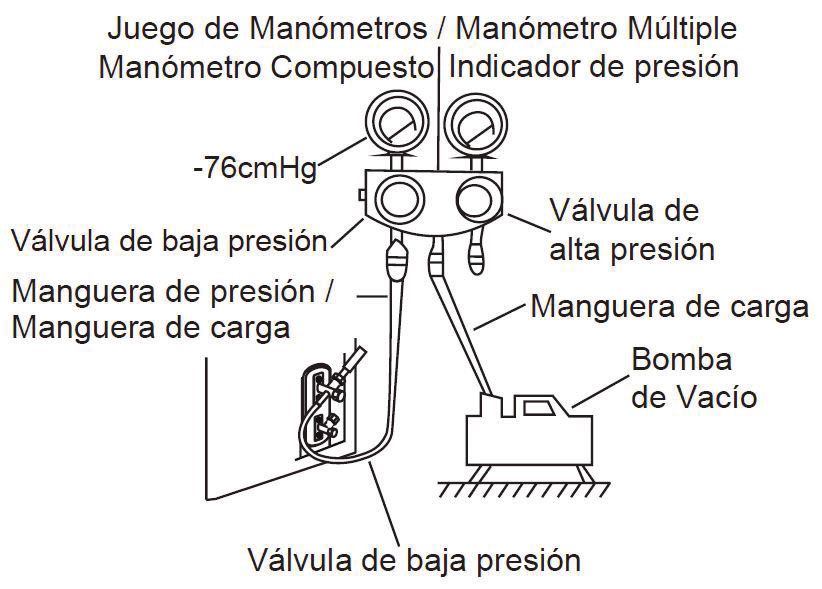
Evacuation Instructions
Before using the manifold gauge and vacuum pump, read their operation manuals to ensure they are used
correctly.
23INSTALLATION INSTRUCTIONS
Evacuation Instructions
1. Connect the charge hose of the manifold gauge to the service port on the outdoor unit’s low pressure
valve.
2. Connect another charge hose from the manifold gauge to the vacuum pump.
3. Open the low pressure side of the manifold gauge. Keep the high pressure side closed.
4. Turn on the vacuum pump to evacuate the system.
5. Run the vacuum for at least 15 minutes or until the compound meter reads -76cmHG (-105 Pa).
6. Close the low pressure side of the manifold gauge and turn off the vacuum pump.
7. Wait for 5 minutes then check that there has been no change in the system pressure.
8. If there is a change in the system pressure, refer to the Gas Leak Check section for information on how
to check the system for leaks. If there is no change in the system pressure, unscrew the cap from the
packaged high pressure valve.
9. Insert hexagonal wrench into the packed high pressure valve and open the valve by turning the wrench
in a 1/4 clockwise turn. Listen for gas to exit the system, then close the valve after 5 seconds.
10. Watch the pressure gauge for 1 minute to ensure there is no change in the pressure. The pressure
gauge should read slightly higher than atmospheric pressure.
11. Remove the charge hose from the service port.
12. Using a hexagonal wrench, fully open both the high pressure and low pressure valves.
13. Tighten valve caps on all three valves, (service port, high pressure and low pressure) by hand.
Tighten further with a torque wrench if necessary.
WARNING
DO NOT MIX
REFRIGERANT TYPES
24INSTALLATION INSTRUCTIONS
Note: Open valve stems gently. When opening valve stems, turn the hexagonal wrench until it hits against
the stopper. Do not try to force the valve to open further.
Note: Some systems require additional charging depending on pipe lengths. The standard pipe length varies
according to local regulations. For example, in North America, the standard pipe length is 7.5 m (25 feet).
In other areas, the standard pipe length is 5 m (16 feet). The additional refrigerant to be charged can be
calculated using the formula in the below chart.
Additional Refrigerant Per Pipe Length
Connective Pipe Air Purging Additional Refrigerant
Length (m) Method
< Standard Pipe Vacuum Pump N/A
Length
Liquid Side: Ø 6.35 (ø 0.25 in) Liquid Side: Ø 9.52 (ø 0.375 in)
> Standard Pipe Vacuum Pump Inverter R410a: Inverter R410a:
Length (Pipe Length - SPL) x 15g/m (Pipe Length - SPL) x 30g/m
(Pipe Length - SPL) x 0.16oZ/ft (Pipe Length - SPL) x 0.32oZ/ft
SPL = Standard Pipe Length
25INSTALLATION INSTRUCTIONS
ELECTRICAL AND GAS LEAK CHECKS
Electrical Safety Checks
After installation, confirm that all electrical wiring is installed in accordance with local and national
regulations and according to the installation manual.
Check Grounding Work
Before completing a test run, measure grounding resistance by visual detection and with grounding
resistance tester. Grounding resistance must be less than 4.
Check for Electrical Leakage
During the test run, use an electroprobe and multimeter to perform a comprehensive electrical leakage test.
If electrical leakage is detected, turn off the unit immediately and call a licensed electrician to find and
resolve the cause of the leakage.
WARNING
ALL WIRING MUST COMPLY WITH LOCAL
AND NATIONAL ELECTRICAL CODES
AND MUST BE INSTALLED BY A LICENSED
ELECTRICIAN.
Gas Leak Checks
There are two acceptable methods of checking for gas leaks.
Soap and Water Method
Using a soft brush, apply soapy water or liquid detergent to all pipe connection points on the indoor and
outdoor units. The presence of bubbles indicates a leak.
Leak Detector Method
If using a leak detector, refer to the device’s operation manual for proper usage instructions.
Note: After completing gas leak checks, confirm that all piping connection points do not leak and make sure
to replace the valve cover on the outdoor unit.
26INSTALLATION INSTRUCTIONS
TEST RUN
Before completing a test run, make sure to complete all electrical safety checks and gas leak checks.
Confirm that the unit’s electrical system is safe and operating properly. Check all flare nut connections and
confirm that the system is not leaking.
Test Run Instructions
1. Connect power to the unit.
2. Press the ON/OFF button on the remote to turn the unit on.
3. Press the MODE button to scroll through the following functions:
• COOL - select lowest possible temperature
• HEAT - select highest possible temperature
4. Allow each function to run for 5 minutes and perform the following checks:
• No electrical leakage
• Unit is properly grounded
• All electrical terminals are properly covered
• Indoor and outdoor units are solidly installed
• All pipe connection points do not leak
• Water drains properly from the drain hose
• All piping is properly insulated
• Unit performs COOL function properly
• Unit performs HEAT function properly
• Indoor unit louvers rotate properly
• Indoor unit responds to the remote control
IMPORTANT: During operation, the pressure of the refrigerant circuit will increase. This may reveal leaks that
were not present during the initial leak check. Take time during the test run to double check that all refrigerant
pipe connection points do not have leaks.
5. After the test run is successfully complete, use the remote control to return the unit to normal operating
temperature. Using insulation tape, wrap the indoor refrigerant pipe connections that were left uncovered
during the indoor unit installation process.
Test Run in Low Temperature
If the ambient temperature is below 17oC (62.6 F), the COOL function will not run when using the remote
control. In this instance, use the manual control button to test the COOL function.
1. Lift the front panel of the indoor unit and raise it until it clicks into place.
2. The manual control button is located on the right-hand side of the unit. Press it two times to select the
COOL function.
3. Perform test run as normal.
Disposal Guidelines
This appliance contains refrigerant and other potentially hazardous materials. When disposing of this ap-
pliance, the law requires special collection and treatment. Do not dispose of this appliance as household
waste or unsorted municipal waste.
27LIMITED IN-HOME APPLIANCE WARRANTY
LIMITED
This quality product is warranted to be free from manufacturer’s APPLIANCE
defects WARRANTY
in material and workmanship, provided that the unit is used under the normal operating
conditions intended by the manufacturer.
Thisquality
This warranty isproduct
available only to the person toto
is warranted whom
be the
freeunitfrom
was originally sold by Danby Products
manufacturer’s defectsLimited (Canada) orand
in material Danbyworkmanship,
Products Inc.provided
(U.S.A.) (hereafter
that the
“Danby”) or by an authorized distributor of Danby, and is non-transferable.
unit is used under the normal operating conditions intended by the manufacturer.
This warranty is available only to the person to whom the unit was originally sold by Danby Products Limited (Canada)
or Danby Products Inc. (U.S.A.) (hereafter “Danby”)TERMS or by OF an authorized distributor of Danby, and is non-transferable.
WARRANTY
Plastic parts, are warranted for thirty (30) days only from purchase date, with no extensions provided.
TERMS OF WARRANTY
Plastic parts,
First Year are warranted for thirty (30) days only
During the first twelve (12) months, any functional from
partspurchase
of this productdate,
found towith no extensions
be defective, provided.
will be repaired or replaced, at warrantor’s
option, at no charge to the ORIGINAL purchaser.
First 24 months During the first twenty-four (24) months, any functional parts of this product found to be defective,
To obtain willreserves
Danby be replaced, at warrantor’s
the right to limit the boundaries ofoption,
“In Home at no charge
Service” to the
to the proximity of anORIGINAL purchaser.
Authorized Service Depot. Any app liance
Service requiring service outside the limited boundaries of “In Home Service” , it will be the consumer’s responsibility to transport the appliance (at
Nothing within this warranty shalltoimply
their own expense) that
the original Danby
retailer (point will be responsible
of purchase) or a service depot or for
liable
repair.for any spoilage
See “Boundaries of In Homeor Serv
damage to ice”food
below. or
Contact your dealer from whom your unit was purchased, or contact
other contents of this appliance, whether due to any defect of the appliance, or its use, whether proper or improper. your nearest authorized Danby service depot, where service
must be performed by a qualified service technician.
If service is performed on the units by anyone other than an authorized service depot, or the unit is used for commercial appli
EXCLUSIONS cation, all
obligations of Danby under this warranty shall be void.
Save as herein provided, by Danby, there are no other warranties, conditions, representations or guarantees, express
or implied, made or intended by Danby or its authorized distributors and all other warranties, conditions, representa-
Boundaries of If the appliance is installed in a location that is 100 kilometers (62 miles) or more from the nearest service center your unit must be
tions
In Homeor Service
guarantees,delivered including to theany
nearestwarranties,
authorized Danby conditions,
Service Depot,representations
as service must only beorperformed
guarantees underqualified
by a technician any Sale of Goods
and certif Act
ied for
or like legislation orwarranty statuteservice
is hereby
by Danby.expressly
Transportation excluded.
charges to and Save as service
from the herein provided,
location Danby
are not protected by shall not be
this warranty and responsible
are t he for
any damages to persons or property,
responsibility including the unit itself, howsoever caused or any consequential damages arising
of the purchaser.
from the malfunction of the unit and by the purchase of the unit, the purchaser does hereby agree to indemnify and
hold harmless
Nothing within thisDanby
warranty shallfrom any
imply thatclaim
Danby willforbedamages
responsible ortoliable
persons or property
for any spoilage or damagecaused
to food orby
otherthe
c unit. ontents of this appliance, whether due
to any defect of the appliance, or its use, whether proper or improper.
GENERAL PROVISIONS
No warranty or insurance herein contained or set out shall apply when damage or repair is caused by any of the
EXCLUSIONS
following:
Save as herein provided, Danby, there are no other warranties, conditions, representations or guarantees, express or implied, m ade or intended by Danby or its
authorized distributors and all other warranties, conditions, representations or guarantees, including any warranties, conditio ns, representations or guarantees
1)under
Power failure.
any Sale of Goods Act or like legislation or statue is hereby expressly excluded. Save as herein provided, Danby shall no t be responsible for any damages
to persons or property, including the unit
2) Damage in transit or when moving the appliance. itself, howsoever caused or any consequential damages arising from the malfunction o f the unit and by the purchase of
the unit, the purchaser does hereby agree to indemnify and hold harmless
3) Improper power supply such as low voltage, defective house wiring or inadequate fuses. Danby from any claim for damages to persons or propert y caused by the unit.
4) Accident, alteration, abuse or misuse of the appliance such as inadequate air circulation in the room or abnormal
operating conditions (extremely high or low room temperature). GENERAL PROVISIONS
5) Use for commercial or industrial purposes (ie. If the appliance
No warranty or insurance herein contained or set out shall apply when damage is not
or repair is caused installed
by any in a domestic residence).
of the following:
6) Fire, water damage, theft, war, riot, hostility, acts of God such as hurricanes, floods etc.
1) Power failure.
7) Service
2) Damagecallsinresulting
transit or whenin moving
customer education.
the appliance.
8) Improper
3) Improper Installation
power supply(ie. suchBuilding-in
as low voltage, of a free
defective housestanding appliance
wiring or inadequate fuses.or using an appliance outdoors that is not
approved for outdoor
4) Accident, alteration,application).
abuse or misuse of the appliance such as inadequate air circulation in the room or abnormal operating con ditions
(extremely high or low room temperature).
Proof 5)of purchase
Use for commercialdateorwill be required
industrial purposes (ie. for
If thewarranty
appliance is notclaims;
installedplease
in a domesticretain bills of sale.
residence).
6) Fire, water damage, theft, war, riot, hostility, acts of God such as hurricanes, floods etc.
7) Service calls resulting in customer education.
8) Improper Installation (ie. Building-in of a free standing appliance or using an appliance outdoors that is not approved for out door application).
Proof of purchase date will be required for warranty claims; so, please retain bills of sale. In the event warranty service is required, present this document to our
AUTHORIZED SERVICE DEPOT.
Warranty Service
In-home
Danby Products
Danby Products Limited
Limited Danby Products
Danby Products Inc. Inc.
POPOBox 1778,
Box 1778, Guelph,
Guelph, Ontario, Ontario,
Canada N1HCanada
6Z9 N1H 6Z9 1-800-263-2629
1-800-263-2629 PO BoxPO669, Findlay,
Box 669, Ohio,
Findlay, Ohio, U.S.A.
U.S.A. 45840 45840
Telephone: (519)
Telephone: (519) 837-0920
837-0920 FAX: (519) FAX:
837-0449(519) 837-0449 12/19 Telephone:Telephone:
(419) 425-8627
(419) 425-8627 FAX: (419)
FAX: (419) 425-8629
425-8629
04/09Consignes de sécurité importantes
LIRE ET SUIVRE TOUTES LES INSTRUCTIONS DE SÉCURITÉ
PRÉCAUTIONS DE SÉCURITÉ • Tout le câblage doit être organisé de manière
Une mauvaise installation liée à l’omission appropriée pour garantir que le couvercle
d’instructions peut entraîner de graves du tableau de contrôle puisse se refermer
dommages ou blessures. correctement. Si le couvercle du tableau de
contrôle n’est pas correctement refermé, cela
• Lorsque vous raccordez la tuyauterie de peut favoriser la corrosion, qui à son tour pourrait
réfrigérant, ne laissez pas de substances ou de chauffer les points de raccordement de la
gaz autres que le réfrigérant spécifié pénétrer borne, déclencher un incendie ou entraîner des
l’unité. La présence d’autres gaz ou substances décharges électriques.
réduira la capacité de l’unité et pourra entraîner • In certain functional environments, such as
une pression anormalement élevée au cours du kitchens, server rooms, etc., the use of specially
cycle de réfrigération. Cela peut provoquer une designed air conditioning units is highly
explosion et vous blesser. recommended.
• L’installation doit être effectuée par un distributeur • Cet appareil n’est pas destiné à être utilisé par
ou spécialiste agréé. Une installation défectueuse des personnes (y compris des enfants) dont les
peut entraîner des fuites d’eau, des décharges capacités physiques, sensorielles ou métalliques
électriques ou un incendie. peuvent être différentes ou réduites, ou qui ont de
• En Amérique du Nord, l’installation doit être l’expérience ou des connaissances, à moins que
effectuée conformément aux exigences de la ces personnes ne reçoivent de supervision ou de
NEC et de la CEC uniquement par le personnel formation pour faire fonctionner l’appareil par
autorisé. une personne responsable de leur sécurité.
• Contactez un technicien d’entretien agréé • N’installez pas l’unité dans un lieu susceptible
pour réparer ou effectuer des opérations de d’être exposé à des fuites de gaz combustible. Si
maintenance sur cette appareil. du gaz combustible s’accumule autour de l’unité,
• N’utilisez que les pièces, pièces spécifiées et cela peut déclencher un incendie.
accessoires inclus pour l’installation. L’utilisation • N’utilisez pas cet appareil dans une pièce
de pièces non standard peut entraîner des fuites humide, comme une salle de bain ou une
d’eau, des décharges électriques, un incendie et buanderie. Une trop grande exposition à l’eau
une défaillance de l’unité. peut provoquer un court-circuit des composants
• Installez l’unité à un emplacement stable et électriques.
solide, capable de supporter son poids. Si • L’appareil doit être correctement mis à la terre ou
l’endroit choisi ne peut pas supporter le poids de des chocs électriques peuvent survenir.
l’unité, ou si l’installation n’est pas correctement • Installez la tuyauterie de drainage conformément
effectuée, il est possible que l’unité tombe, ce aux instructions de ce manuel. Un mauvais
qui pourrait entraîner de graves blessures et drainage peut causer des dégâts d’eau.
dommages.
• Pour tous les travaux électriques, respectez REMARQUE CONCERNANT LES GAZ
toutes les normes et réglementations locales et FLUORÉS
nationales concernant le câblage, ainsi que le • Ce climatiseur est un appareil hermétiquement
manuel d’installation. Pour l’alimentation, vous scellé et contient des gaz fluorés. Pour obtenir
devez utiliser un circuit indépendant et une seule des informations spécifiques sur le type et
prise. Ne branchez pas d’autres appareils sur la quantité de gaz, veuillez vous reporter à
cette prise. Les capacités électriques insuffisantes l’étiquette concernée apposée sur l’appareil en
ou les défauts des travaux électriques peuvent elle-même.
entraîner des décharges électriques ou incendies. • L’installation, le service, l’entretien et la réparation
• Utilisez les câbles spécifiés pour tous les travaux de cet appareil doivent être effectués par un
électriques. Raccordez et serrez fermement les technicien qualifié.
câbles pour éviter que des forces extérieures • La désinstallation et le recyclage de l’appareil
n’endommagent la borne. Les mauvais doivent être effectués par un technicien qualifié.
raccordements électriques peuvent entraîner • Si l’appareil dispose d’un système de détection
une surchauffe et un incendie, mais aussi des des fuites, l’absence de fuites doit être vérifiée au
décharges électriques. moins tous les 12 mois. Lors de la vérification des
fuites, un relevé approprié de tous les contrôles
est fortement recommandé.
GARDER CES INSTRUCTIONS!
29INSTRUCTIONS D’INSTALLATION
ACCESSOIRES
Le système de climatisation comprend les accessoires suivants. Utilisez toutes les pièces d’installation et les
accessoires pour installer le climatiseur. Une mauvaise installation peut provoquer des fuites d’eau, des chocs
électriques, des incendies ou provoquer l’échec de l’équipement.
Dénomination Description Quantité
Plaque de montage 1
Vis de fixation de la plaque
de montage ST3.9 X 25 5
Agrafe d’ancrage 5
Télécommande 1
Batterie sèche AAA.LR03 2
Joint d’étanchéité 1
Raccord d’évacuation 1
30INSTRUCTIONS D’INSTALLATION
RÉSUMÉ DE L’INSTALLATION - UNITÉ INTÉRIEURE
Plaque de montage mural
Panneau avant
Câble d’alimentation
Aérateur
Conduite de drainage
Filtre fonctionnel
à l’avant du filtre principal Câble de signal
Conduite de réfrigérant
Télécommande
Câble d’alimentation de
l’appareil extérieure
Remarque: Les illustrations de ce manuel ne sont fournies qu’à des fins explicatives. Il est possible que la
forme de votre unité intérieure soit légèrement différente. La véritable forme de l’unité doit prévaloir.
31INSTRUCTIONS D’INSTALLATION
RÉSUMÉ DE L’INSTALLATION - UNITÉ INTÉRIEURE
32INSTRUCTIONS D’INSTALLATION
RÉSUMÉ DE L’INSTALLATION - UNITÉ INTÉRIEURE
33INSTRUCTIONS D’INSTALLATION
INSTALLATION DE L’APPREIL INTÉRIEURE
Avant d’installer l’appareil intérieure, reportez-vous à l’étiquette figurant sur la boîte du produit pour vous
assurer que le numéro de modèle de l’appareil intérieure correspond à celui de l’appareil extérieure. Le
numéro de modèle de l’appareil intérieur se terminera par un “-I” et le numéro de modèle de l’appareil
extérieur se terminera par un “-O”, sinon ils devraient être identiques.
Étape 1 : choix du lieu d’installation
Voici les normes qui vous aideront à choisir le lieu approprié à l’appareil.
• Bonne circulation d’air.
• Évacuation pratique.
• Le bruit de l’unité ne dérangera pas d’autres personnes.
• Stable et solide; l’emplacement d’installation ne vibrera pas.
• Solidité suffisante pour supporter le poids de l’appareil.
• À au moins 1 m (3 pieds) de tous les autres appareils électriques, comme les téléviseurs, les radios et les
ordinateurs, qui pourraient avoir un impact sur le signal à distance infrarouge.
N’installez PAS l’appareil dans les lieux suivants:
• À proximité d’une source de chaleur, de vapeur ou de gaz combustible.
• À proximité d’éléments inflammables, par exemple, des rideaux ou du linge.
• À proximité d’un obstacle susceptible de bloquer la circulation d’air.
• À proximité d’une porte d’entrée.
• Dans un lieu directement exposé à la lumière du soleil.
Reportez-vous au schéma suivant pour vous assurer que la distance séparant l’appareil des murs et du
plafond est appropriée:
34INSTRUCTIONS D’INSTALLATION
Étape 2 : installation de la plaque de fixation sur le mur
La plaque de fixation est la pièce sur laquelle vous installerez l’appareil intérieure.
1. Retirez la vis fixant la plaque de fixation à l’arrière de l’appareil intérieure.
2. Placez la plaque de montage contre le mur dans l’endroit où l’appareil intérieur sera installé.
3. Percez les trous pour les vis de montage, en veillant à ce que les vis pénètrent dans les goujons de mur
qui peuvent supporter le poids de l’appareil.
4. Vissez la plaque de fixation au mur avec les vis fournies. Assurez-vous que la plaque de fixation est bien
à plat contre le mur.
Remarque: Si le mur est en brique, en béton ou autre matériau similaire, percez des trous de 5 mm de
diamètre (0,2 pouce) dans le mur et insérez-y les douilles d’ancrage fournies. Fixez ensuite la plaque au
mur en serrant les vis directement sur les douilles.
Dimensions de la plaque de fixation
Différentes plaques de fixation correspondent aux différents
modèles. Pour vous assurer que vous disposez de
suffisamment d’espace pour installer l’unité intérieure, vérifiez
les diagrammes ci-dessous qui montrent les deux types de
plaques de montage ainsi que les dimensions suivantes:
• Largeur de plaque de fixation.
• Hauteur de plaque de fixation.
• Largeur de l’appareil intérieure par rapport à la plaque.
• Hauteur de l’appareil intérieure par rapport à la plaque.
• Emplacement recommandé pour le trou dans le mur, que
ce soit du côté gauche ou droit de la plaque de fixation.
• Distances relatives entre les trous de vis.
Modèle A 34.8 cm (13.7”)
Modèle B 40.1 cm (15.78”)
3.7 cm (1.45”)
17.9 cm (7.05”) 22.9 cm (9.01”)
4.2 cm (1.65”)
10.1 cm (4”) 22.8 cm (8.98”)
13.6 cm (5.35”) 12.6 cm (4.96”)
4.9 cm (1.95”)
29.7 cm (11.7”)
4.7 cm (1.85”)
29 cm (11.4”)
Contour de l'unité Contour de l'unité
intérieure intérieure
4.9 cm (1.95”)
5.8 cm (2.28”)
Trou de paroi Trou de paroi Trou de paroi Trou de paroi
arrière gauche arrière droite arrière gauche arrière droite
6.5 cm (2.5”) 72.2 cm (28.45”) 6.5 cm (2.5”) 6.5 cm (2.5”) 80.2 cm (31.6”) 6.5 cm (2.5”)
Modèle C 51.7 cm (20.37”)
Modèle D
5.8 cm (2.3”)
57.8 cm (22.8”)
14.4 cm (5.65”)
13.8 cm (5.45”)
22.1 cm (8.7”) 29.8 cm (11.7”)
31.9 cm (12.55”)
5.7 cm (2.25”)
5.4 cm 7.9 cm(3.1”) 5.4 cm (2.1”)
Contour de l'unité
(2.1”)
intérieure
33.6 cm (13.2”)
14.9 cm Contour de l'unité
4.9 cm (1.9”)
4 cm (1.55”)
(5.9”) intérieure
Trou de paroi Trou de paroi
arrière gauche arrière droite Trou de paroi 4.9 cm (1.9”) Trou de paroi
6.5 cm (2.5”) 6.5 cm (2.5”) arrière gauche
3.4 cm (1.35”) arrière droite
96.5 cm (38”)
6.5 cm (2.5”) 13.8 cm (5.4”) 14.9 cm (5.9”) 6.5 cm (2.5”)
108 cm (42.5”)
35You can also read