Hybrid RF/VLC Systems: A Comprehensive Survey on Network Topologies, Performance Analyses, Applications, and Future Directions - arXiv
←
→
Page content transcription
If your browser does not render page correctly, please read the page content below
ARXIV VERSION UPLOADED: JULY 5 2020, ABUELLA ET AL.: HYBRID RF/VLC SYSTEMS SURVEY 1

 Hybrid RF/VLC Systems: A Comprehensive Survey
 on Network Topologies, Performance Analyses,
 Applications, and Future Directions
 Hisham Abuella, Student Member, IEEE, Mohammed Elamassie, Member, IEEE, Murat Uysal, Fellow, IEEE,
 Zhengyuan Xu, Senior Member, IEEE, Erchin Serpedin, Fellow, IEEE, Khalid A. Qaraqe, Senior Member, IEEE,
 and Sabit Ekin, Member, IEEE
arXiv:2007.02466v1 [eess.SP] 5 Jul 2020

 Abstract—Wireless communications refer to data transmissions I. I NTRODUCTION
 in unguided propagation media through the use of wireless
 carriers such as radio frequency (RF) and visible light (VL) Wireless communication systems have undergone many
 waves. The rising demand for high data rates, especially, in indoor changes and developments since their inception that coincide
 scenarios, overloads conventional RF technologies. Therefore,
 technologies such as millimeter waves (mmWave) and cognitive with the discovery of electromagnetic waves (EM) and wire-
 radios have been adopted as possible solutions to overcome the less telegraph to the present day as advanced technologies such
 spectrum scarcity and capacity limitations of the conventional RF as smartphones, connected vehicles and the Internet of Things
 systems. In parallel, visible light communication (VLC) has been (IoT) became widely available. All these new technologies rely
 proposed as an alternative solution, where a light source is used on wireless communication to adapt to the common demand
 for both illumination and data transmission. In comparison to RF
 links, VLC links present a very high bandwidth that allows much for high bandwidth and data rates. Over the past decades,
 higher data rates. VLC exhibits also immunity to interference mobile communications that started with first-generation (1G)
 from electromagnetic sources, has unlicensed channels, is a very and followed by second, third, fourth and fifth generations
 low power consumption system, and has no health hazard. VLC (2G, 3G, 4G, and 5G) in addition to the wireless fidelity (Wi-
 is appealing for a wide range of applications including reliable Fi) standards for short-range wireless communication (IEEE
 communications with low latency such as vehicle safety commu-
 nication. Despite the major advantages of VLC technology and a 802.11) have evolved rapidly especially in terms of data rate,
 variety of its applications, its use has been hampered by its cons capacity, and medium access methods.
 such as its dependence on a line of sight connectivity. Recently, The idea of millimeter-wave (mmWave) systems was lately
 hybrid RF/VLC systems were proposed to take advantage of the introduced to cope with over-occupied low-frequency bands.
 high capacity of VLC links and better connectivity of RF links.
 Unfortunately, using RF systems in the mmWave band has
 Thus, hybrid RF/VLC systems are envisioned as a key enabler
 to improve the user rates and mobility on the one hand and to a lot of challenges in terms of channel modeling and trans-
 optimize the capacity, interference and power consumption of the mission power. However, channel modeling and measurements
 overall network on the other hand. This paper seeks to provide a for this band were reported by a lot of studies such as [1].
 detailed survey of hybrid RF/VLC systems. This paper represents Despite these challenges, mmWave systems are seen as one
 an overview of the current developments in the hybrid RF/VLC
 of the strongest candidates for 5G systems and some IEEE
 systems, their benefits and limitations for both newcomers and
 expert researchers. standards for these systems were introduced as in [2] (IEEE
 802.11ad for the 60 GHz band). Alternatives to traditional RF
 Index Terms—Radio frequency (RF), visible light communi- systems in terms of mmWave systems are discussed in [1],
 cation (VLC), hybrid RF/VLC, wireless fidelity (Wi-Fi), hybrid [3], [4].
 networks, hybrid RF/VLC environments. As an alternative to communication systems that operates in
 the RF band (3 kHz to 300 GHz), the use of visible light (VL)
 band (400 THz to 800 THz) for wireless communications has
 been proposed. The idea of using light to transmit a signal
 H. Abuella and S. Ekin are with the School of Electrical and has been proposed by Bell and Tainter in 1880 (photo-phone)
 Computer Engineering, Oklahoma State University, Oklahoma, USA (e- as discussed in [5]. However, the idea of transmitting data
 mail: hisham.abuella@okstate.edu, sabit.ekin@okstate.edu). using a light source was first introduced using a fluorescent
 M. Elamassie and M. Uysal are with the Department of Electrical
 and Electronics Engineering, Ozyegin University, Istanbul, Turkey, (e-mail: lamp in [6]. Later, the idea of using the fast switching light-
 m.amassie@gmail.com, murat.uysal@ozyegin.edu.tr). emitting diodes (LEDs) was discussed for the first time in [7].
 Z. Xu is with the University of Science and Technology of China, Hefei, As early as the 2000s in Japan, the white-LED was used
 China (e-mail: xuzy@ustc.edu.cn).
 E. Serpedin is with the Department of Electrical and Computer Engi- for both illumination and communication by researchers at
 neering, Texas A&M University, College Station, Texas, USA (e-mail: es- Keio University [8]. After this achievement, numerous studies
 erpedin@tamu.edu). have been published on how to make use of white-LEDs in
 Q. A. Qaraqe is with the Department of Electrical and Com-
 puter Engineering, Texas A&M University at Qatar, Doha, Qatar (e- communication systems. Based on visible light communication
 mail: khalid.qaraqe@qatar.tamu.edu). (VLC) technology, light fidelity (Li-Fi) was then proposed
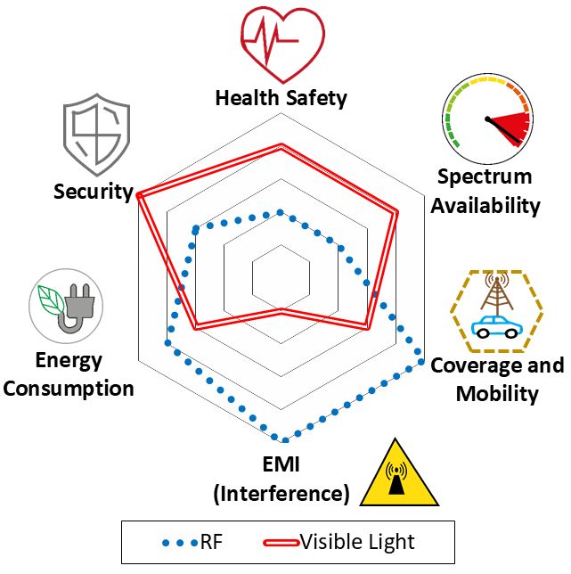
ARXIV VERSION UPLOADED: JULY 5 2020, ABUELLA ET AL.: HYBRID RF/VLC SYSTEMS SURVEY 2

 solution in 5G systems. Chowdhury et al. in [18] discuss the
 possibility of using a hybrid RF and optical wireless network
 to meet the 5G requirements. They provide a brief overview
 of optical wireless networks and the possible hybrid network
 architectures and describe the possible research directions and
 improvements for hybrid RF/VLC networks. Moreover, mul-
 tiple surveys discussing the improvements of VLC and Li-Fi
 networks have discussed the idea of hybrid RF/VLC networks
 as in [19]–[21]. A recent survey was published on arXiv [22]
 which focuses more on optimizing the Li-Fi/ Wi-Fi network
 parameters (user behavior modeling, interference management,
 handover, and load balancing) and did not focus on the general
 RF/VLC systems. In addition, a general overview of the optical
 wireless hybrid systems and current research trends and issues
 in network layer level is presented in [23]. After the publishing
 of [18], a large number of studies have been reported on the
 design and performance analyses of these systems as described
 in chronological order in Table IX.
 This survey focuses on achieving the following goals:
Fig. 1. Comparing the pros and cons of VLC & RF standalone systems.
 1) Highlighting the design aspects of VLC systems such as
 channel modeling, system performance, advantages, and
in [9], [10] to form a small-cell wireless access network where limitations.
multiple light sources in an indoor environment are used as 2) Highlighting the RF technologies that are used in hybrid
access points (APs). systems and their corresponding channel models.
 In 2011, the first IEEE standard related to VLC (802.15.7) 3) Offering readers a general understanding of hybrid
was published by IEEE 802.15 working group for Wire- RF/VLC systems, their history, and the desired goals
less Personal Area Networks. The details of this standard intended to accomplish.
pertaining to data rates, modulation schemes, and dimming 4) Pointing out the contributions of the major hybrid
mechanisms are discussed in [11]. After the introduction of RF/VLC studies according to their network topology and
the VLC idea, a lot of studies and surveys discussed the performance analysis.
possible applications, advantages, and limitations of these 5) Outlining the challenges in the development of hybrid
systems, see e.g., [12], [13]. In [14], the authors presented RF/VLC systems, future research directions, and possi-
the limitations and advantages of using VLC as a candidate ble promising applications.
for 5G systems. In [12], Pathak et al. discussed the details 6) Comparing all of the existing studies on hybrid RF/VLC
of VLC based systems and some of the possible applications systems in terms of the employed technologies, network
like VLC sensing and indoor localization and even using of topologies and main features.
VLC in vehicle-to-vehicle (V2V) communication. In [15], 7) Pinpointing research challenges, future research direc-
Uysal et al. discussed the usage of VLC in V2V and the tions, and possible applications.
achieved data rate limitations when utilizing LED headlamp The rest of the paper is organized as follows. VLC and
used by automotive industry in VLC. In [16], Chowdhury et RF systems are presented in Section II. Hybrid RF/VLC
al. provided an overview on optical wireless communication systems, network topologies, performance analysis studies,
systems and their network architectures and applications. system-level simulations, and implementations are discussed
 Fig. 1 summarizes the weaknesses and strengths of RF and in Section III. Research directions and emerging applications
VLC systems as standalone networks. Based on these, there of hybrid RF/VLC systems are presented in Section IV. This
are several studies investigating how RF and VLC systems survey ends with concluding remarks on the potential of hybrid
can be used as a complementary technology to each other. RF/VLC systems. Nomenclature and key symbols used in the
Analogously, numerous studies have proposed hybrid RF/VLC paper are summarized at the end of the paper.
systems to overcome the limitations of VLC by using RF
technology in conjunction with the VLC systems.1 II. VLC AND RF T ECHNOLOGIES
 To our best knowledge, the only tutorial discussing hybrid In this section, we provide an overview of the VLC and
RF/VLC systems was published in [17], [18]. Ayyash et al. RF systems highlighting the used modulation techniques and
in [17] discuss the coexistence opportunities of Wi-Fi and channel properties. We further compare these two systems
Li-Fi systems, the opportunities that these systems present motivating the need for developing hybrid RF/VLC systems.
for off-loading of Wi-Fi systems and the challenges faced by
these wireless heterogeneous networks (HetNets) as a future A. VLC Systems
 1 The research carried out on hybrid RF/VLC are chronologically ordered The main requirement for a VL source to be used in
and summarized in Table IX. a communication link is that the light intensity should be
ARXIV VERSION UPLOADED: JULY 5 2020, ABUELLA ET AL.: HYBRID RF/VLC SYSTEMS SURVEY 3

modulated at a rate higher than 200 Hz [11] to avoid any DAC Amplifier Bias Tee LED
flickering effects to the human eyes. Despite this minor re- Data source
 +
quirement, VLC research has shown that high data rates can be Modulator
achieved (nearly 100 Mb/s in IEEE 802.15.7 [11]). Moreover,
as previously discussed, there are a lot of motivations behind
using the VL band. First, the availability of a huge unlicensed Channel
spectrum in the optical band (VL band). Second, the very high
 DC Voltage
frequency of this band makes VL unable to penetrate objects
and walls. This property of the VL band allows the reusing of Data Sink
 +
the same bandwidth for small cells since there is no inter-cell Demodulator
interference due to cells placed in different rooms or buildings. ADC Pre-amplifier PD
Moreover, the high path loss and inability to penetrate walls
 Fig. 2. Block diagram of the basic structure of the VLC system.
improve further the security of VLC systems since it is
impossible for anyone outside the building to eavesdrop on
the inside-the-building VLC network. Third, the VLC systems
can be deployed using the existing illumination infrastructure user equipment (UE)’s side with a VLC transmitter. Moreover,
especially in indoor scenarios, which will make the system VLC is sensitive to interference caused by other light sources
energy and cost-efficient. Fourth, VL-based systems do not which can be clearer in daylight or outdoor scenarios. Also, the
interfere with existing RF-systems, and thus, VLC systems dimming mode for using VLC in low light scenarios can be an
can be used in RF-sensitive areas like in hospitals, airplanes, issue although an advanced modulation technique (enhanced
nuclear plants, etc. Therefore, the advancements that happened unipolar orthogonal frequency division multiple access (eU-
in indoor lighting industry (LEDs ) and in photodetectors OFDM) [29]) has been proposed for Li-Fi systems to operate
(PDs) technology made VLC possible. at very low light intensity scenarios while keeping a reasonable
 Despite the major advantages of VLC technology and data rate. An important design consideration for VLC networks
variety of its applications, its use has been hampered by its is the LED connectivity to the internet source. Typically,
cons such as its dependency on the line of sight connectivity VLC networks present a large number of APs of LED arrays
that results in low coverage of VLC-based networks and its which make internet connectivity challenging. Most of these
performance is heavily influenced by front-end bandwidth and limitations have been recognized in literature and solutions
losing of the LOS link due to mobility and shadowing. have been proposed to resolve them [30]. We will outline the
 Despite the fact that the optical channel of visible light is main solutions later in this survey.
in the order of THz, the bandwidth of commercial LEDs is Next, we will focus on introducing the basic VLC system
limited. It has been shown that the LEDs modulation band- components, modulation techniques and channel properties
width is in the order of MHz to hundreds of MHz [24]. This that help in developing a robust hybrid RF/VLC system with
makes it a bottleneck for achieving high-rate transmission. respect to the limitations outlined above. Fig. 2 depicts the
Different efforts have been conducted to address this. The basic structure of the VLC system. We will later outline the
first optical transmitter that was adopted is phosphor-converted main differences between the RF systems and VLC systems.
LED. The bandwidth of a phosphor-converted LED is limited It is clear that the base-band algorithms will not change a
because of its slow response. A post-equalization circuit which lot except for the fact that LEDs and PDs operate in the
consists of one active equalizer and two passive equalizers was non-negative voltage range, unlike the RF antennas. At the
then proposed to extend the bandwidth up to 150 MHz [25]. transmitter side, an LED is used instead of an antenna in the
Utilizing the fact that if higher bandwidth LEDs are employed, RF system. This LED needs two inputs: an analog signal and a
the bandwidth can be significantly increased. For example, 1 direct current (DC) supply to drive the LED. Additionally, like
Gbps was reported by the using micro LEDs as transmitters in the RF-based systems, a digital to analog converter (DAC)
[26]. is used to convert the digital signal into an analog signal after
 Different experiments have been conducted in the literature getting the modulated data from the base-band modulator. At
comparing LOS with non-LOS (NLOS) Links. In [27], they the receiver side, a PD is used instead of a receiving antenna
have carried out an experimental studies where the mea- and the signal is amplified by using an electric amplifier,
surements have been done in an empty room for different sometimes adding some optical lens and filters to improve the
scenarios including LOS and NLOS cases. They have con- field of view (FOV) and gain of the receiver. After amplifying
sidered frequency sweeping technique in their measurements the signal, an analog to digital converter (ADC) is used to
by the using of vector network analyser (VNA) in an effort convert the analog signal into a digital signal that is to be
to obtain CIR. While the reflected rays can still be detected processed by the base-band digital demodulator.
in NLOS scenarios, the channel gain severely dropped (see 1) VLC Front-Ends: There are two major types of struc-
[27, Fig. 6]). Similar observations can be seen in [28] where a tures for colored/white LEDs used in general lighting. The
commercially optical and illumination design software is used first type consists of a blue-colored LED with a phosphor layer
for obtaining CIR. Moreover, uplink in VLC systems can be coated on top of it. When an electric current is applied to the
considered as one of the major challenges. Furthermore, the LED, light is emitted from that LED and part of it is absorbed
advancements in the LED industry are still hard to support the by the phosphor to generate the second color. The combination
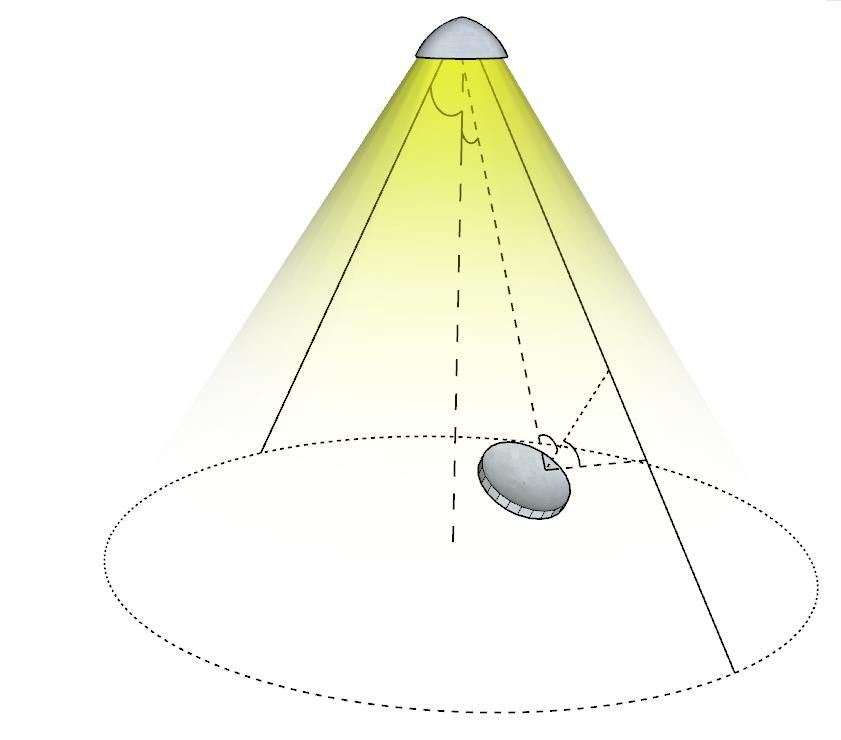
ARXIV VERSION UPLOADED: JULY 5 2020, ABUELLA ET AL.: HYBRID RF/VLC SYSTEMS SURVEY 4

 TABLE I. Comparison of different VLC receivers in terms of cost, data rate, sensitivity, size, power consumption and availability in current UE.
 Photo-detector Solar-cell Imaging-sensor
 Cost Moderate Low High
 Data rate High Moderate Moderate
 Sensitivity Sensitive High Sensitivity Low Sensitivity
 Size Small Large Moderate
 Power consumption Moderate Low High
 Availability in current UE No Rare Available with modification needed

 LED Lamp
 Table I illustrates a comparison between the three methods
 for receiving the signal in VL-based systems in terms of cost,
 data rate, sensitivity, size, power consumption and availability
 max in current UE.
 Distance ( )
 In this survey, it is assumed that the VLC systems use
 normal blue LEDs with a phosphor transmitter and photo-
 detector receivers unless stated otherwise.
 2) VLC Path Loss Models: Several works have been done

 on channel modeling and characterization for indoor opti-
 cal link [34]–[41]. For example, assuming single reflections,
 Gfeller and Bapst in [34] have proposed the first propagation
 PD model. Assuming multiple reflections, Barry et. al. in [35] have
 proposed a recursive simulation model. While the previous
 models were proposed for IR, in 2011, Lee et. al. have
 extended the channel models of IR and produced the first
 indoor channel model for VLC systems [42].
Fig. 3. LED based LOS channel model [33], where a VLC transceiver system For indoor VLC systems as shown in Fig. 3, the transmitter,
model illustrating the parameters of VLC channel models is presented. which is based on LEDs, is generally modeled by a Lambertian
 pattern [35], [43], [44]. The channel gain based on LED with
 Lambertian pattern that considers LED beam solid angle, LED
of these two colored lights results in colored/white light.
 beam maximum half-angle, the angle between the source-
Another type of LED is produced by mixing lights from three
 receiver line and beam axis, and the angle between the source-
primary colored chips (RGB). Three chips emit each color
 receiver line and receiver normal is adopted by most papers
simultaneously and at the output, the required colored/white
 that consider hybrid RF/VLC. VLC path loss models can be
light is produced. The phosphor white LED has the advantage
 summarized as follow:
of low cost. However, the nature of phosphor light conversion
 • Lambertian model:
makes it unsuitable for high-speed data communication due to
phosphorous response time. In other words, white phosphor For indoor VLC, the channel gain of LOS is generally
LEDs (WPLEDs) exhibit a limited bandwidth of few MHz modeled by the Lambertian emission and given by [44]
while RGB LEDs present a higher bandwidth with an order (m+1)AR
of magnitude higher than WPLEDs [31], [32]. Furthermore, Hv = Ts (θ)g(θ)cosm (φ)cos(θ), ∀θ < φmax ,(1)
 2πd2
RGB-LEDs are suitable for color shift keying (CSK) modu- where AR is the optical detector size, and d is the distance
lation technique. This will be discussed in more detail in the between the receiver and the transmitter. φ and θ stand for
VLC modulation methods subsection. irradiance and incidence angles, respectively. In addition,
 On the receiver side, there are three types of receivers that φmax represents the semi-angle at half-power of the LED,
can be used: m is the order of the Lambertian model and is given by
 • Photo-detector (photo-diode) (PD)): ln(2)
 m = − ln(cos φmax ) , Ts (θ) is the gain of the optical filter,
 It is a semiconductor device that converts the light energy and g(θ) is the concentrator gain, which is assumed to
 to a voltage difference and it can support very high data be a constant depending on the concentrator design.
 rates. • Simple path loss model:
 2
 • Solar-cell : In the simple model (similar to the RF path loss model
 It is a larger version of a photo-detector used to collect [1]), the power-distance relation is modeled as follows
 as much light energy as possible.
 • Imaging-sensor: Hv = K[d]−ς , ∀ d > 1, (2)
 It is an array of photo-detectors that can be used to where Hv is the optical channel gain, K is a constant
 improve the data rates. that represents all the gains and the transmitted power
 2 Solar-cells, typically, detect light and other electromagnetic radiation near and ς denotes the channel path loss exponent which
the visible range such as infrared. usually depends on the channel environment. This simple
ARXIV VERSION UPLOADED: JULY 5 2020, ABUELLA ET AL.: HYBRID RF/VLC SYSTEMS SURVEY 5

 model assumes that the channel only has a path loss band is divided into many small bands by the using of
 factor and a gain which is dependent on the system gains orthogonal sub-carriers [53]–[58].
 and interference from the environment. It is used by the • Color shift keying: CSK is a VLC modulation scheme,
 studies where the VLC system is assumed static and only where the data is transmitted by the using of different
 the distance of the LOS is changing without a change in colors with the same intensity [59]–[61].
 the irradiance and incidence angles. 4) VLC Multiple Access Schemes: In VLC, different multi-
 3) VLC Modulation Methods (PHY): The typical candi- ple access methods that allow more than two users/nodes to be
dates for the front-end devices in VLC systems are incoherent connected to the same transmission medium and transmitted
LEDs and laser diodes (LD) because of their low costs. Due to over it have been proposed such as:
their physical characteristics, information can be transmitted • Carrier sense multiple access (CSMA): a user/node tries
by modulating the intensity of the light. Therefore, the trans- firstly to determine if another transmission is in progress
mitted signal should be a unipolar non-negative real-valued before setting up its transmission by the use of carrier-
signal. Such a VLC technique of modulation/demodulation is sense mechanism (CSM). If CSM sensed a current trans-
referred to as IM/DD (Intensity Modulation/ Direct Detection). mission, user/node waits for the current transmission to
For IM/DD, some techniques can be applied in, relatively, be ended [62].
straightforward manner, e.g., pulse width modulation (PWM), • Orthogonal frequency division multiple access
pulse position modulation (PPM), on-off keying (OOK), and (OFDMA): OFDMA is a modified version of the
pulse amplitude modulation (PAM). As the data rate increases, OFDM where multiple access is achieved by assigning
these modulations begin to suffer from the effects of inter- different subcarriers to different users/nodes. This allows
symbol interference (ISI) as a result of frequency selectivity. simultaneous transmission from several users/nodes [63].
Therefore, a more suitable modulation technique is needed. • Code-division multiple access (CDMA): CDMA is a
A typical candidate is orthogonal frequency division multi- channel access scheme where several users/nodes can
plexing (OFDM). Not only OFDM has a flat fading channel send data simultaneously over a single VLC channel.
for each subcarrier but also allows for an adaptive bit and This allows several users/nodes to share the same band
power loading which leads to optimal utilization of available of frequencies without too much interference between
resources. Furthermore, OFDM includes simple equalization them by the use of a special coding scheme where each
in the frequency domain with single-tap equalizers in addition user/node is assigned a special code [64].
to its ability to avoid frequency distortion due to flickering. It • Non-orthogonal multiple access (NOMA): in NOMA,
should be, however, noted that the typical OFDM signals are users/nodes share the available time and frequency re-
bipolar complex-valued. Therefore, the standard OFDM must sources simultaneously, which leads to low latency and
be modified in order to make it suitable for IM/DD. better spectral efficiency [65]. NOMA systems can be
 On the other hand, the use of light, simultaneously, for accomplished in two domains, i.e., power or code do-
illumination and data communication purposes poses some mains. The most commonly used one is NOMA with a
challenges that require consideration in implementing the VLC power domain where different power levels are assigned
system. The two main challenges are dimming support and to different users/nodes. On the other hand, in the NOMA
flicker mitigation. Typically, the lighting fixture is equipped scheme with code-domain, multiplexing is accomplished
with dimming control that allows users to control the level of by the use of spreading sequences similar to CDMA
brightness they prefer. While flicker is observed by the human technology.
eye as a result of continuous switching between on and off It should be further noted that the access method can be a
during data transmission. part of multiple access protocol (MAP) and control mechanism
 The main modulation schemes presented in the literature (CM), which is known as medium access control (MAC).
can be itemized as follows: MAC deals with issues such as assigning channels to different
 • On-off keying: OOK is the simplest form of modulation users/nodes.
 that represents data in VLC as, typically, the presence
 or absence of light. In this form, the presence of light B. RF Systems
 represents a binary one, while the absence represents a
 Since RF systems are old and well-established technology,
 binary zero. Some more sophisticated OOK schemes vary
 researchers have used multiple standards and bands to improve
 the duration of presence and absence [45]–[48].
 their performance. Most of the proposed solutions employ Wi-
 • Pulse modulation: Pulse modulation is a simple modula-
 Fi (microWave) technology. Conventional Wi-Fi operates in
 tion scheme where the transmitted signal is presented in
 frequency ranges that are below 6 GHz3 . In this frequency
 form of pulses [49]–[52]. It is classified into three major
 range, the data rate is in the range of several 100 Mbps. For
 types:
 achieving several Gbps, some studies explored the possibility
 – Pulse-width modulation/Pulse-duration modulation of using mmWave systems instead of old microWave systems.
 – Pulse-amplitude modulation
 3 There are several RF ranges for Wi-Fi communications: 900 MHz, 2.4
 – Pulse-position modulation
 GHz, 3.6 GHz, 4.9 GHz, 5 GHz, 5.9 GHz, and 60 GHz bands”. However,
 • Orthogonal frequency division multiplexing: OFDM is communication with 60 GHz is limited to a few meters and can not pass
 a multi-carrier technique, where the available frequency through walls compared to conventional Wi-Fi frequencies.
ARXIV VERSION UPLOADED: JULY 5 2020, ABUELLA ET AL.: HYBRID RF/VLC SYSTEMS SURVEY 6

 TABLE II. Utilized RF wireless technologies in hybrid RF/VLC systems.
The different RF systems used in RF/VLC systems studies can
be classified in the following categories: RF Channel Model References
 Wi-Fi (2.4 GHz/5 GHz) [18], [75]–[97]
 1) Wi-Fi: Wi-Fi is a wireless communication technology
 WINNER II Channel Model
that refers to the IEEE communications standards for wireless [98]–[106]
 (2-6 GHz)
local area networks (i.e., IEEE 802.11) and was created in mmWave (60 GHz) [90], [107]–[110]
1997. This technology which is based on the direct sequence DSRC (5.9 GHz) [111]
spread spectrum (DSSS) and frequency-hopping spread spec-
trum (FHSS) uses radio signals that allow accessing the
internet while moving from one place to another via high- TABLE III. Comparison of VLC and RF technologies that explains the main
speed network connections. IEEE 802.11 supports up to 2Mb/s motivating factors behind hybrid RF/VLC networks.
data rates. Different versions of Wi-Fi (i.e., different standards) VLC RF
have been proposed: IEEE 802.11a which works on the 5 GHz Range Low (Up to 100 m) High (Up to 1km)
band and yields a maximum of 54Mb/s is based on OFDM Environment
 Sensitive Moderate
 dependency
and was created in 1997. IEEE 802.11b works on the 2.4 GHz
 Ambient light Sensitive Not affected
band and offers a maximum of 11Mb/s and was created in
 EMI No Yes
1999. IEEE 802.11g works on the 2.4 GHz band, provides a Band license Unlicensed Licensed/Unlicensed
maximum of 54Mb/s and was created in 2003. IEEE 802.11n Cost Low High
works on the 2.4 GHz and 5 GHz bands were created in Size Small Large
2009. This standard supports multi-channel with a maximum Power consumption Low High
of 150Mb/s/channel. In addition, IEEE 802.11ac was invented
in 2014, and this standard increases the data rate up to 1300
Mb/s [66], [67].
 • IEEE P1609.2-Security Layer: Standard for Security Ser-
 2) mmWave: Most commercial radio communications in- vices for Applications and Management Messages.
cluding Wi-Fi work in a narrow band of the RF spectrum (i.e., • IEEE P1609.3-Network and Transport Layers: Standard
300 MHz-3 GHz). However, the part of the RF spectrum above for Networking Services.
3 GHz is mostly unexploited for commercial applications. • IEEE P1609.4-MAC Layer: Standard for Multi-Channel
Recently, there is a huge interest in utilizing this range. For Operation.
example, the range 3.1-10.6 GHz has been proposed for high • IEEE P1609.11: Standard for WAVE– Over-the-Air Elec-
data rate connectivity in personal area networks. The range tronic Payment Data Exchange Protocol for Intelligent
57-64 GHz is used to provide data rates at the order of Transportation Systems (ITS)
Gbps for short-range local area networks. Furthermore, the • IEEE P1609.12: Standard for WAVE - Identifier Alloca-
range of 28-30 GHz has been proposed for local multipoint tions
distribution services. Millimeter waves can support high data
rates at the order of Gbps but are severely affected by the Table II shows how different hybrid RF/VLC systems
absorption caused by oxygen molecules and water vapors from studies employ different RF channel models based on the RF
the atmosphere. Since oxygen absorbs EM waves at around system assumed in each study.
60 GHz, the frequency range 57-64 GHz can experience huge
attenuation on the order of 15 dB/km. On the other hand, the C. Comparison of RF and VLC Technologies
range 164-200 GHz is severely affected by the concentration
of water vapors in the atmosphere and may be subject to In this section, the comparison of RF and VLC technologies
attenuation on the order of tens of dB/km [68]–[70]. (Table III [15], [17]) is presented.
 As shown in Table III, VLC offers more flexibility in terms
 3) Dedicated Short Range Communications (DSRC):
 of the angle of incidence and beam-width with the same
DSRC is a wireless communication standard that is designed
 high accuracy percentage. In terms of physical size, the VLC
specifically for short and medium communication ranges.
 transceiver is expected to be much smaller as it only needs a
It is used mainly for vehicular communications, i.e., V2V,
 PD, which can be very small in size similar to the PDs used
vehicle-to-infrastructure (V2I) and infrastructure-to-vehicle
 in [112] and [113]. On the other hand, RF systems need to
(I2V) communications. DSRC systems exploit microwaves in
 have the transceiver module and the antenna which depends on
the ranges of 5.805-5.815 GHz and 5.795-5.805 GHz [71].
 the frequency of operation. In addition, some limitations that
The first version of it has been proposed in 1999 [72]. In
 need to be considered in the future work are the channel model
2003, an improved version referred to as the American Society
 estimation in real-time and the performance during different
for Testing and Materials (ASTM)-DSRC standard has been
 light and environment scenarios. Due to the fact that light wave
proposed [72]. DSRC is not just for PHY and MAC layers,
 has a higher frequency than RF wave used in RF systems, the
it is, actually, a complete communication protocol. The list of
 operation (distance) range in VLC will be smaller than that
DSRC IEEE standards is [73], [74]:
 in RF, as expected. However, VLC systems present immunity
 • IEEE 802.11p-PHY Layer: to EM interference (EMI), make use of unlicensed bands and
 • IEEE P1609.1: Standard for Wireless Access in Vehicular present low power consumption (since VL is already used for
 Environments (WAVE) - Resource Manager. illumination) [15], [114].
ARXIV VERSION UPLOADED: JULY 5 2020, ABUELLA ET AL.: HYBRID RF/VLC SYSTEMS SURVEY 7

 The motivating factors behind using VLC are summa- the installation cost is very low [120]. Moreover, the
rized as follows: current drives and controls the luminous intensity of
 LEDs, common VLC systems use the IM/DD scheme.
 • RF spectrum scarcity problem: When using LEDs for VLC, the interconnection of VL
 The supporting band for the traditional RF communica- networks can be achieved through existing power line
 tions is 300 K - 300 GHz. An application for wireless infrastructure [121]. Therefore, VLC is compatible with
 spectrum resources requires in general a high license fee the smart power grid.
 and a long waiting period. With the rapid development • Coherence time:
 of wireless communications services, the global wireless Since VLC is subject to significantly less multipath
 spectrum resources are in short supply. VL presents effects, the coherence time of the VLC channels is at least
 a huge bandwidth of 400-790 THz. Thus, the visible an order of magnitude larger than that of the RF channels.
 spectrum range is 10,000 times larger than that of the Thus, VLC requires less frequent channel estimation, a
 entire RF wireless spectrum. Furthermore, no license is feature which is especially important for situations that
 required for VLC [115]. require continuous and stable linking. In addition, higher
 • Reduced capacity of RF-based systems: coherence time means that VLC is a good fault-tolerant
 VLC technology assumes higher communication band- technology [114].
 widths by using higher frequency light waves to carry
 The key limiting factors of using VLC are summarized as
 information. At the same time, due to the good direction-
 follows:
 ality of the VL beam and weak diffraction, VLC can make
 use of diversity and multiplexing techniques to greatly • Uplink hardware issues:
 expand the capacity of the communication system [116]. Uplink communication for VLC represents a challenge
 • Minimum EM interference: as it requires updating the user’s hardware. The signal
 VLC generates almost no EM radiation in space, which emitted from the LED to the photodiode on the mobile
 provides a good wireless communication solution for phone only solves the downlink communication problem,
 environments with EM interference sensitive devices or and the mobile phone needs to send a signal back to
 where radio silence is required [114]. ensure the communication link is unblocked, but the
 • Signal secrecy: design of the reverse communication link is difficult
 Due to the long wavelength and antenna architecture, RF [122].
 communication presents weak directionality and can be • Interference and noise from other light sources and
 easily tracked by non-target receivers. In VLC, since the inter-cell interference:
 light wavelength is short, light is subject to directionality Other unmodulated artificial light sources and natural
 and attenuation effects and can’t penetrate walls when light sources sometimes work in the same spectral band
 it propagates in space. Thus, light can only be received with the VLC systems. If the ambient light source is
 in a specific area and the confidentiality of transmitted strong enough, it will increase the intensity of the shot
 information is ensured [117]. noise or saturate the receiving end and the VLC systems
 • Energy efficiency: can not function properly [114].
 Compared to traditional light sources, LEDs present • Communication and lighting integration:
 higher electro-optic conversion efficiency. If LEDs can be As a communication and lighting integration technology,
 used to provide communication services while lighting, indoor VLC must balance the dual user requirements of
 they will definitely save a lot of energy. Therefore, lighting and communication. The transmission of infor-
 the concept of integrated lighting communication has mation in VLC relies on changing the luminous intensity,
 also been proposed [118]. Furthermore, compared to RF and flickering may occur during communication, which
 femtocell networks, VLC systems could achieve a very is not allowed in daily lighting and can seriously affect
 large area spectral efficiency gain [119]. the user’s lighting experience. VLC needs to meet the
 • Health safety: corresponding lighting requirements in both lightings on
 Compared with infrared radiation (IR) communications, and lighting off modes [123].
 an improper application of IR can cause damage to the • Terminal (user) mobility and handover overhead:
 human body due to the high temperature since IR is a If the receiver or transmitter is mobile, the received
 kind of heat radiation. For example, strong IR rays can power on the detector array will fluctuate. The channel
 cause skin burns or damage the retina of the fundus. matrix will have to be updated over time. Soft handover
 Under normal lighting conditions, the use of VLC does mechanisms are especially important to extract these
 not pose any safety problems for the human body [13]. fluctuations and maintain a more stable connection when
 • Pervasive infrastructure (LEDs): the light detection is handed over from one photo-detector
 Due to the gradual widespread adoption of LEDs as to another [124].
 the fourth generation of lighting technology, lighting • Signal coverage (the high attenuation rate of the
 facilities represent a natural platform for VLC. Only signal):
 communication modules need to be added to the existing In VLC, cell sizes are considerably smaller due to the
 lighting facilities to implement the VLC function, so high directivity of light and smaller transmission dis-
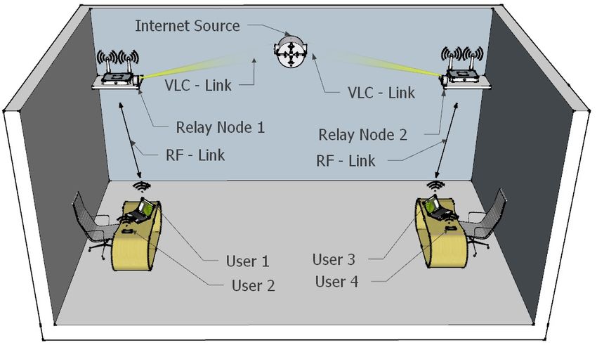
ARXIV VERSION UPLOADED: JULY 5 2020, ABUELLA ET AL.: HYBRID RF/VLC SYSTEMS SURVEY 8

 tances, thus the signal coverage area is limited. If the the direct current component and collects energy from the
 beam angle of the transmitter is increased, the detected optical signal and then uses the collected energy for retrans-
 signal intensity will be relatively reduced [125]. mitting data. Exact and asymptotic expressions for secure
 • Shadowing, due to losing the LOS link: outage probability and average secrecy capacity considering
 As VL cannot penetrate obstacles, indoor VLC is built the effect of system parameters were also derived. In [128], the
 for the LOS link. Thus, the transmission is influenced secrecy capacity of DF-based hybrid RF/VLC was compared
 by the blocking objects due to the random movement of with standalone RF and VLC systems and it was showed that
 people in a room. However, clear LOS is expected for the hybrid had better performance. This paper also analyzed
 the receivers of lighting systems at most time [126]. the framework of non-adaptive power allocation where both
 • VLC network access to Internet: the source and relay present the same amount of power and
 The indoor VLC system must be connected to the base the case of cooperative power-saving where the total average
 station to achieve the communication objective. The most power is shared between source and relay in a way that
 practical problem is how to construct a VL wireless minimizes the total power while satisfying the required secrecy
 access network consisting of dozens or even hundreds capacity. In [129], the effect of positions’ randomness of both
 of VL APs that are distributed over the ceiling since it relay and destination on outage probability of cooperative
 is difficult to install new communication cables between hybrid RF/VLC wireless sensor networks was investigated.
 different fixed networks and LED lights or among the Decode & forward (DF) and amplify & forward (AF) relay-
 LED lights [96]. ing schemes were analyzed and approximate expressions for
 outage probability were derived. In [130], outage and BER
 III. H YBRID SYSTEMS performances of AF relay-assisted hybrid RF/VLC systems
 were investigated. Closed-form expressions for the outage
 This section discusses the hybrid RF/VLC studies in more probability were derived using probability density function
detail. It is divided into the following subsections: hybrid (PDF) and moment generating function (MGF) approaches
networks typologies, hybrid RF/VLC environments, optimiza- and by considering the effect of emission angle. The effect
tion and smart technologies, performance analyses, hybrid of timing errors on BER performance was also considered. In
network simulation and system implementation, and current [131], taking into account the randomness of relay’s and des-
applications of hybrid systems. Fig. 5 presents an overview of tination’s locations, the outage and symbol error probabilities
the main studies and it enables the readers to navigate easier of a hybrid RF/VLC assuming DF and AF relaying schemes
through the topic of interest. were derived.
 In [132], a new multi-user hybrid RF/VLC was proposed.
A. Hybrid Networks Topologies In this system, users are divided into pairs. The near user
 receives from source via VLC and forwards the information to
 The following three types of hybrid RF/VLC networks
 its paired user through RF transmission. In [133], a learning
topologies were proposed in literature4 :
 algorithm-knowledge transfer context-aware hybrid RF/VLC
 1) Dual-Hop Hybrid RF/VLC System: In this type of hybrid
 system that takes into account the traffic type, location, and
system, the user access link is either VLC or RF. The network
 time was proposed. The presented simulation results illustrated
model where the user access link is RF can be observed in
 that the proposed system could significantly improve the
Fig. 6.
 convergence speed and performance of reinforcement learning-
 The first component of the system is the communication
 based network algorithms. In [134], the secrecy performance
between the VLC source (base station) and relaying nodes.
 of relay-jammer selection beamforming hybrid RF/VLC was
The communication is carried out using VLC (LOS-link) in
 investigated assuming the absence of a direct link between
both uplink and downlink. Due to the fixed positions of the
 source and destination. The considered system presents multi-
relay nodes and base-station, it is believed the maximum data
 ple DF relays and the relay node is selected by minimizing the
rate can be achieved using the LOS VLC system.
 outage probability. The jamming node is then selected from
 The second component is the communication between the
 the available relaying nodes based on the received signal-to-
end-user and (plug-and-play) relay node (AP). The commu-
 noise ratio (SNR) at the eavesdropper location. Furthermore,
nication is accomplished using a low power directional RF
 beamforming vectors for both RF and VLC subsystems were
system by dividing the area into cells using a concept similar
 designed and exploited in minimizing the consumed power.
to that of mobile base stations. Dividing large areas into
 In [135], the outage performance of the IoT hybrid RF/VLC
small cells will provide the advantage of serving multiple
 system was investigated considering the randomness of the
users and saving power, simultaneously. Furthermore, RF
 positions of devices. VLC was considered for the downlink
communication schemes such as handover, multi-relaying, and
 from the source lamp to the IoT devices while RF with the
beamforming (via directional antennas) can be applied to this
 NOMA scheme for the uplink. All IoT devices are equipped
system, if needed.
 with PD for two purposes: data communication and energy
 In [127], the secrecy performance of a hybrid RF/VLC
 harvesting from the light emitted by the source LED lamp.
system was investigated assuming that the relay node extracts
 These devices are then using the harvested energy to transmit
 4 While ”Heterogeneous” is commonly used for parallel hybrid RF/VLC data to the RF receiver. Approximate expressions for the
networks, some references used it for dual-hop hybrid RF/VLC. outage probability were also derived. In [136], a medical
ARXIV VERSION UPLOADED: JULY 5 2020, ABUELLA ET AL.: HYBRID RF/VLC SYSTEMS SURVEY 9

 Classification of hybrid RF/VLC systems.
 Fig. 5.
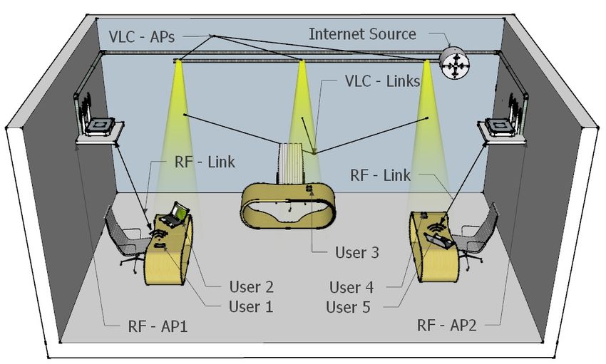
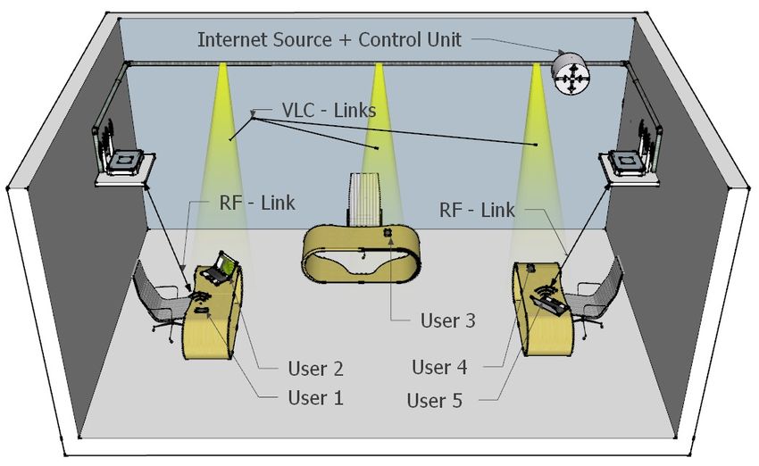
ARXIV VERSION UPLOADED: JULY 5 2020, ABUELLA ET AL.: HYBRID RF/VLC SYSTEMS SURVEY 10

Fig. 6. Hybrid RF/VLC Dual-hop systems.
 Fig. 7. Hybrid RF/VLC systems: Opportunistic separate networks.

health care AF relaying RF/VLC system was proposed. In the
proposed system, the RF link is for the outdoor link whereas
the VLC is for the indoor link. The outage probability was
also investigated assuming generalized K-fading in RF link.
 2) Opportunistic Separate Networks (RF/VLC): Two sep-
arate VLC and RF networks with the user deciding on the
better system to be used. This network model is presented
in Fig. 7. In this network, the users are free to choose the
best network depending on several parameters like SNR of
the system, application requirements, mobility of the user, etc.
This type of network is hard to control and optimize. Some
 Fig. 8. Hybrid RF/VLC systems: Heterogeneous networks with centralized
of the studies adopted this model because of its low network unit.
overhead and its flexibility to the users. However, it is hard to
control the users when there is a high number of users in the
same place competing for the same resource without a control and robustness of the proposed scheme.
unit dividing the resources. Therefore, as the number of users 3) Heterogeneous Networks (HetNet) with Centralized
increases, it is hard to adopt this model. Unit: As shown in Fig. 8, the heterogeneous system consists
 The coverage and rate analysis of opportunistic cellular of RF and VLC networks with a central control unit. Based on
RF/VLC and other network configurations were investigated the network conditions, the central unit assigns the resources
and compared in [98]. Based on approximations of the com- to the user, and sometimes having the location of the user
plementary error function (erfc) and cumulative distribution helps the network to optimize the resources and interference
function (CDF) of a Gamma random variable, an approximate better. This type of network presents high network overhead
expression for coverage was derived. It was shown that the data but it makes sure that all users are getting equal treatment
opportunistic selection based on the maximum received signal (network fairness). Therefore, this network is needed when a
power is more suitable for scenarios where the interference high number of users are present in a small area network.
effects are not dominant. On the other hand, the opportunistic In [139], the optimal resource-allocation of mobile terminals
scheme deteriorates the performance for higher interference in a heterogeneous wireless network under diverse QoS was
scenarios, due to wrongfully connecting to RF networks with considered. A decentralized algorithm was proposed to address
higher interference instead of VLC networks. Hybrid cellu- the resource allocation problem. In [140], a heterogeneous
lar RF/VLC has also been considered in [137]. This paper cellular network that combines RF and VLC to maximize the
presented both theory and implementation demonstrating the energy efficiency of the entire communication system under
feasibility of heterogeneous RF/VLC network for IoT. Par- QoS requirements was considered. The optimization problem
ticularly, a hybrid cellular architecture that allows internet- is not convex and it is addressed using successive convex
operability between different technologies was proposed. They approximations. In [91], a heterogeneous hybrid RF/VLC
further discussed different applications such as localization, system where users can estimate their position based on
long-range communication, and monitoring. the information broadcasted by VLC lamps was investigated.
 In [138], a hybrid RF/VLC system was investigated with one Based on the locations of users, the Wi-Fi unit allocates
RF AP and multiple VLC APs assuming that all APs perform the resources of VLC enabled lamps. In [136], a medical
NOMA. Considering the fact that grouping users in the NOMA health care AF relaying RF/VLC system was proposed. In
system is challenging, this reference addressed the grouping of the proposed system, the RF is assumed for the outdoor link
users using the coalitional game theory. In particular, a merge- whereas the VLC is considered for the indoor link.
and-split algorithm that determines the optimal user grouping Depending on system link-level topology of the system,
is presented. A comparison of the proposed system with the the number of users and complexity of the system needed,
conventional opportunistic scheme points out the effectiveness different authors chose the network model that fits their study
ARXIV VERSION UPLOADED: JULY 5 2020, ABUELLA ET AL.: HYBRID RF/VLC SYSTEMS SURVEY 11

 TABLE IV. Hybrid RF/VLC studies: Network topologies.
 users requests and maintaining an acceptable illumination
 Network topology References level. Reference [140] investigates a heterogeneous cellular
 [84], [127], [129]–[131], [136], [141]– network that combines RF and VLC in order to maximize
 Dual-hop
 [143] the energy efficiency of the whole communication system
 [18], [76]–[79], [83], [91], [97], [98], under QoS requirements. In [158], a heterogeneous RF/VLC
 Opportunistic separate [100], [104], [105], [132], [140], [144]–
 [155] for wireless industrial networks is developed that can support
 [80]–[82], [85], [89], [90], [93]–[95], different QoS requirements such as high reliability, low latency
 HetNet with centralized
 [99], [101]–[103], [107], [109], [128], and high data rates of IoT and industrial networks IoT (IIoT)
 unit
 [133], [134], [139], [156]–[169]
 devices. They have proposed a new deep post-decision state-
 TABLE V. Hybrid RF/VLC studies: Objective optimization problems. based experience replay and transfer (PDS-ERT) learning
 algorithm in order to maximize the network energy efficiency.
 Single-objective optimization problem On the other hand, in [157] a collaborative RF with lightwave
 References Objective resource allocation scheme was proposed for enhancing the
 Minimizing the power consumption subject to satisfying
 [76] the users requests and maintaining the acceptable illumi- energy harvesting of the overall network which consists of
 nation level. one multi-antenna RF AP, multiple optical transmitters, and
 Maximize energy efficiency of the entire communication multiple terminal devices. Under an outage probability con-
 [140]
 system under QoS requirements.
 Selecting the network that provides the best long term
 straint, minimizing the area power consumption (APC) by
 [133] optimizing the RF and VLC (Base stations) BSs intensities
 average performance.
 Maximizing energy efficiency of a network by new deep in [170]. Utilizing the knowledge of location information of
 [158]
 PDS-ERT learning algorithm.
 Enhancing the energy harvesting of the overall network
 user terminals, a location information-aided load balancing
 [157] that consist of one multi-antenna RF AP, multiple optical (LB) design for the hybrid RF/VLC networks was proposed in
 transmitters, and multiple terminal devices. [75] to maximize the throughput under proportional fairness
 Minimizing the area power consumption (APC) under an constraints. In [171], a hybrid RF/VLC network that consists
 [170]
 outage probability constraint.
 Maximizing the throughput under proportional fairness of more than one RF and VLC APs has been considered.
 [75]
 constraints. Therefore, they have increased the degree of freedom for
 Allocation of available APs with the objective of increas- selecting the AP that the node should be connected to. Thus, an
 [171]
 ing the overall throughput.
 Multi-objective optimization problem optimization problem for the allocation of these APs with the
 References Objective objective of increasing the overall throughput was proposed.
 [159] Outage reduction and system capacity improvement. 2) Multi-Objective Optimization (MOO): MOO is an op-
 Reducing communications power consumption and min- timization problem that considers more than one objective
 [77]
 imizing the queue lengths.
 function simultaneously or sequentially (i.e., adopts multiple
 objective functions). Reference [159] investigates a multi-
as shown in Table IV. objective optimization problem for selecting either RF or VLC
 In terms of the utilization of the system resources, there are at each device-to-device pair in a multi-user communication
two categories that can describe a hybrid RF/VLC system: network. The proposed solution consists of a two-phase al-
 gorithm in which the change from RF to VLC depends on
 • Aggregated Technology:
 the interference caused to other devices and the interference
 Where users employ both VLC and RF technologies at
 received from other device-to-device pairs. The first phase of
 the same time to improve their data rate and reliability
 the algorithm is for outage probability reduction while the
 of the connection.
 second phase is for system capacity improvement. It is shown
 • Non-Aggregated Technology:
 that the performance of the proposed algorithm is close to
 Where users employ only one of the two technologies
 the exhaustive search algorithm that minimizes outage and
 to optimize the network conditions and manage the
 maximizes capacity but presents less computational complex-
 interference present in the network.
 ity. Reference [77] investigates the optimization of network
 resources in hybrid RF/VLC networks to reduce energy con-
B. Resource Allocation sumption for the communication task while minimizing the
 Different hybrid RF/VLC optimization problems spanning queue lengths.
different topics such as resource allocation, transmit power In optimizing hybrid RF/VLC communication systems, an
minimization, load balancing and handover have been con- important problem is establishing the constraint conditions.
sidered in the literature and are summarized in Table V. Since the hybrid communication systems include both RF
These optimization problems can be divided generally into and VLC transceivers, the constraints are divided into two
two categories: categories: lighting and coupling constraints, respectively.
 1) Single-Objective Optimization (SOO): SOO is an op- • Lighting Constraints:
timization problem with a single objective function. As an Since VLC needs to maintain illumination and commu-
example of SOO, reference [76] considers an energy-efficient nication requirements simultaneously, several constraints
hybrid RF/VLC system for wireless access networks for joint should be considered. Due to the requirement of in-
lighting and communications. The optimization problem is tensity modulation in VLC, the transmit signal has to
to minimize the power consumption subject to satisfying the satisfy the non-negative constraint [172]. In order to
ARXIV VERSION UPLOADED: JULY 5 2020, ABUELLA ET AL.: HYBRID RF/VLC SYSTEMS SURVEY 12

 TABLE VI. Hybrid RF/VLC studies: Performance analyses.
 avoid excessive nonlinear distortions, it is sufficient to
 consider the peak optical power or a peak-to-average- Analysis References
 [84], [104], [105], [109], [176],
 power ratio (PAPR), which in general are constrained to Achievable data-rate
 [177]
 guarantee that the LED is working in the linear region Average transmission delay
 [77], [78], [87], [88], [139], [144],
 [173]. The transmission of information in VLC relies [144], [153], [158], [163]
 Packet loss probability and BER [88], [130], [131], [142]
 on changing the luminous intensity. However, flickering [18], [75], [78]–[82], [85], [90],
 may occur during communication, a condition that is [92], [95], [98], [108], [129], [132],
 Network coverage and outage
 not allowed in daily lighting and can seriously affect [135], [141], [144], [145], [152],
 probability
 [159], [161], [164], [167], [178]–
 the user’s lighting experience. For illumination purposes, [180]
 dimming constraints are desirable features to consider [82], [94], [107], [109], [110],
 Network fairness
 [174]. For multi-color VLC, it is necessary to ensure [139], [156], [162], [167], [169]
 that the illumination meets the white light constraint. [83], [93], [153], [163], [164],
 Handover overhead
 [167], [168], [178]
 Using MacAdam ellipse as a statistical measuring tool, [76], [77], [99]–[104], [128], [134],
 the small chromaticity difference between two colors in Energy and power efficiency [140], [143], [145], [158], [170],
 the same luminance color map can be described. Due [171], [181]–[183]
 Area spectral efficiency [94], [106]
 to the limitation of human eyes in color recognition, Secrecy outage probability and se- [127], [128], [134], [143], [146],
 when two colors are on the same MacAdam ellipse, crecy rate [147], [184]–[186]
 ordinary human observers cannot distinguish between the
 two colors [173].
 • Coupling Constraints:
 In the dual-hop RF/VLC systems, the RF and VLC sys- each technology has different channel model and B is
 tems work in serial, the data rate of the mobile terminals the user assigned bandwidth.
 are constrained by the system where the transmission In [90] and [81], an efficient AP selection scheme for
 speed is slower [86]. In heterogeneous RF/VLC systems, hybrid RF/VLC networks is proposed. Based on the dif-
 the RF and VLC systems work in parallel such that the ferent channel characteristics, a tailor-made AP selection
 mobile terminals aggregate the data from both networks. method for the hybrid network is formulated as a two-
 Hence, the data rate at the mobile terminals is constrained stage algorithm, which first determines the users that need
 by the total data rate of the RF and VLC systems [104]. service from Wi-Fi and then performs AP selection for
 The optimization problem is constrained by the power the remaining users. The simulation results show that the
 budget for these two serial/parallel communication links proposed method achieves a near-optimal throughput.
 such that Pt-VLC + Pt-RF ≤ Pt , where Pt is the maximum Reference [79] proposed an indoor VLC-Wi-Fi hybrid
 allowable total power [105]. In [175], the channel corre- network experimental platform that integrates multiple
 lation in VLC over broad spectra is analyzed. However, links with multiple access, hybrid network protocol, user
 for hybrid RF/VLC systems, the coupling constraints of mobility management mechanisms, and cell handover.
 the RF and VLC channels have not been investigated yet The proposed hybrid VLC-Wi-Fi network exhibits better
 and it represents an important problem for future studies. coverage and greater network capacity. In [95], a dynamic
 load balancing scheme that considers handover overhead
 in a hybrid RF/VLC network is proposed. The throughput
C. Performance Analyses performance is analyzed across the service areas and the
 effects of the handover overhead on handover locations
 Most of the existing studies have conducted different per-
 and user throughput are discussed.
formance analyses. In Table VI, the studies discussing the
 • Average transmission delay (end-to-end delay):
same investigations are grouped to enable researchers an easy
 Average transmission delay is the average time needed to
comparison. Moreover, a list of the main studies carried out
 send a packet from source (transmitter) to the receiver in
is presented next.
 the network. This average time includes all the multi-hop
 • User throughput (achievable data rate) of RF/VLC retransmission time (Ttri
 ) (time needed by middle nodes
 networks: to process and retransmit the data), error retransmission
 The average achievable data rate is a critical performance time (Terr ) (time needed when a new data packet is
 metric in any wireless network used to estimate the retransmitted due to an error). Moreover, this parameter
 average user throughput in the network given a certain includes the time delay added due to the handover process
 bandwidth. The average data rate of a user (Ri ) can be (THO ). The average transmission delay (Tavg ) can be
 expressed as follows: expressed as follows:
 Ri = E[B log2 (1 + γi (t))], (3) "N
 X
 #
 i
 Tavg = E (Ttr (t)) + Terr (t)Perr + THO (t)PHO ,
 where E[.] is the expected value operator with respect i=1
 to time domain, γi (t) is the signal to interference and (4)
 noise ratio which changes over time (t) depending on the where PHO , Perr is the probability that a handover
 user location and technology used (VLC or RF) since process is needed and a transmission error occurred,
You can also read