Vector Flight Controller + OSD User Guide - December, 2014 Version 2.0 Software Version 11.48+
←
→
Page content transcription
If your browser does not render page correctly, please read the page content below
Vector Flight Controller + OSD User Guide

                                                              December, 2014

                                                                   Version 2.0

                                                       Software Version 11.48+

© 2014 Eagle Tree Systems, LLC. All Rights reserved.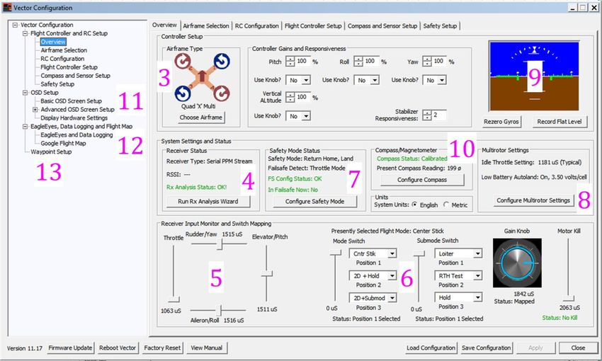
USER GUIDE

                                                                                    Table of Contents
1             Safety ............................................................................................................................................................................. 6
    1.1 .... Read the Manual!................................................................................................................................................................6
    1.2 .... Special Symbols used in the Manual ..........................................................................................................................6
    1.3 .... General Safety Precautions ............................................................................................................................................6
2             Overview ...................................................................................................................................................................... 7
    2.1 .... Introduction ..........................................................................................................................................................................7
    2.2 .... Packing List ...........................................................................................................................................................................8
    2.3 .... Specifications........................................................................................................................................................................8
    2.4 .... How to Get Help and Request New Features .........................................................................................................9
    2.5 .... Installing the Software, and Updating the Firmware .......................................................................................9
        2.5.1 Software Compatibility ............................................................................................................................................................. 9
        2.5.2 Downloading the Latest Software ....................................................................................................................................... 9
        2.5.3 Updating your Vector Firmware ....................................................................................................................................... 10
    2.6 .... Getting Notified about Important Vector Updates .......................................................................................... 10
    2.7 .... Glossary of Terms used in the Manual ................................................................................................................... 11
3             Connecting the Vector.......................................................................................................................................... 13
    3.1 .... Vector Controller Connections .................................................................................................................................. 13
        3.1.1 Backup Power ............................................................................................................................................................................ 13
    3.2 .... Vector GPS/Mag and Current Sensor/PSU Connections ............................................................................... 14
    3.3 .... Vector Current Sensor/PSU Power Output .......................................................................................................... 15
    3.4 .... Current Sensor Maximum Continuous Current, and Load Testing .......................................................... 15
    3.5 .... Vector Wiring .................................................................................................................................................................... 16
        3.5.1 Vector Video Harness + Connecting your Video Camera and Transmitter .................................................... 16
        3.5.2 Providing power to your Video Transmitter and Camera ..................................................................................... 17
        3.5.3 Vector Audio Harness and Audio Connections ........................................................................................................... 18
        3.5.4 Vector Receiver Harness....................................................................................................................................................... 19
        3.5.5 Receiver Connection Harness Load Capacity (Fixed Wing Only) ....................................................................... 20
        3.5.6 Powering your Receiver on Multirotors ........................................................................................................................ 20
        3.5.7 Connecting Receiver and Servos/ESCs to the Vector .............................................................................................. 22
        3.5.8 Connecting you Receiver’s RSSI Output (if available) ............................................................................................. 25
        3.5.9 Configuring SPPM Based RSSI and Link Quality ........................................................................................................ 25
4             Mounting the Vector and Accessories ........................................................................................................... 26
    4.1 .... Mounting the Vector ...................................................................................................................................................... 26
                                                                                                                                                                                                              ii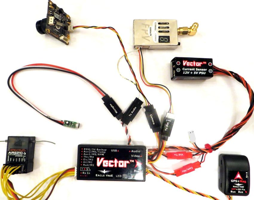
USER GUIDE
        4.1.1 Mounting Location and Orientation ................................................................................................................................ 26
        4.1.2 Mounting Technique............................................................................................................................................................... 26
    4.2 .... Mounting the GPS/MAG Sensor ................................................................................................................................ 27
        4.2.1 GPS Signal Interference ......................................................................................................................................................... 27
        4.2.2 Magnetometer Interference ................................................................................................................................................ 27
        4.2.3 GPS/MAG Mounting Orientation ....................................................................................................................................... 27
        4.2.4 The GPS Stand and Clip ......................................................................................................................................................... 28
    4.3 .... Mounting the Current Sensor/PSU .......................................................................................................................... 28
    4.4 .... Mounting the Optional Pitot Tube........................................................................................................................... 28
    4.5 .... Controlling the Vector ................................................................................................................................................... 29
        4.5.1 The Mode Switch ...................................................................................................................................................................... 29
        4.5.2 The Submode Switch .............................................................................................................................................................. 29
        4.5.3 The Gain Knob ........................................................................................................................................................................... 29
        4.5.4 The Kill Switch (for Multirotors Only) ............................................................................................................................ 30
5             Configuring the Vector ........................................................................................................................................ 30
    5.1 .... Configuration Overview................................................................................................................................................ 30
    5.2 .... Transmitter Channel Mixing ...................................................................................................................................... 30
    5.3 .... Configuring with the Windows Software ............................................................................................................. 31
    5.4 .... Configuring the Vector via Stick Menus ................................................................................................................ 32
        5.4.1 Teaching the Vector about SPPM or S.BUS™ Channel Mappings ........................................................................ 32
        5.4.2 Navigating the Stick Menus ................................................................................................................................................. 33
        5.4.3 Exiting Menu Mode ................................................................................................................................................................. 34
        5.4.4 Accessing Menus during Flight .......................................................................................................................................... 34
    5.5 .... Selecting the Airframe type ........................................................................................................................................ 34
    5.6 .... Accepting the Airframe Type ..................................................................................................................................... 35
    5.7 .... Telling the Vector about Transmitter Dual Surface Mixing ........................................................................ 35
    5.8 .... Running the Receiver Analysis Wizard .................................................................................................................. 35
    5.9 .... Configuring Auxiliary Receiver Inputs and Servo Outputs........................................................................... 37
        5.9.1 Configuring the Auxiliary Input Channel (for non-serial Rx inputs) ................................................................ 37
        5.9.2 Configuring the Vector Auxiliary Output Channels (Fixed wing only) ............................................................ 37
    5.10 . Flight Modes, and Configuring the Mode/Submode Switches .................................................................... 38
        5.10.1         Flight Mode Description ................................................................................................................................................ 38
        5.10.2         Control Stick Function in Multirotor Modes ......................................................................................................... 40
        5.10.3         Programming the Mode Switch .................................................................................................................................. 40
        5.10.4         Programming the Optional Submode Switch ....................................................................................................... 41
    5.11 . Configuring the Flight Controller/Stabilizer...................................................................................................... 42
                                                                                                                                                                                                              iii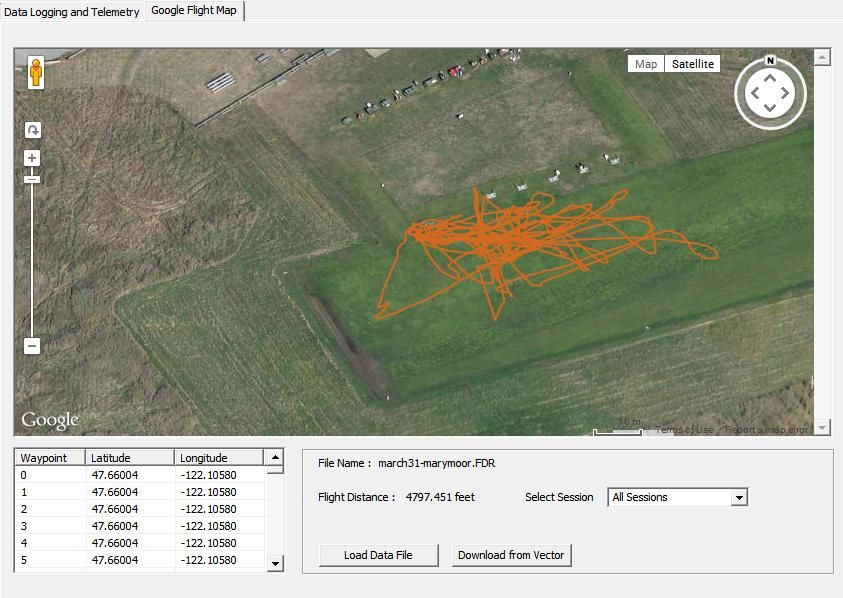
USER GUIDE
        5.11.1         Setting Controller Gains ................................................................................................................................................. 42
        5.11.2         Verifying Correct Control Surfaces Movement (Fixed Wing) ....................................................................... 45
        5.11.3         Confirming ESC Endpoints are set Correctly (Multirotor only) ................................................................... 46
        5.11.4         Arming and Disarming your Multirotor (Multirotor only) ............................................................................ 46
        5.11.5         Setting Idle Throttle (Multirotor only) ................................................................................................................... 47
        5.11.6         Confirming Correct Motor Order and Direction (Multirotor only) ............................................................ 48
        5.11.7         Configuring Low Battery Autoland (Multirotor only) ...................................................................................... 48
        5.11.8         Setting Flat Level Mounting ......................................................................................................................................... 49
        5.11.9         Rezeroing Gyros ................................................................................................................................................................ 49
    5.12 . Configuring Return to Home and other Safety Modes ................................................................................... 49
        5.12.1         Configuring Failsafe Detection ................................................................................................................................... 50
        5.12.2         Configuring RTH/Safety Mode ................................................................................................................................... 52
        5.12.3         Configuring Maximum Altitude and Maximum Distance ................................................................................ 53
    5.13 . The Vector’s LED Indicator ......................................................................................................................................... 53
    5.14 . Configuring the OSD ....................................................................................................................................................... 54
        5.14.1         Adjusting the Display ...................................................................................................................................................... 54
        5.14.2         Setting Display Units (English or Metric) .............................................................................................................. 55
        5.14.3         Choosing what to Display on the OSD Screen ...................................................................................................... 55
        5.14.4         Basic Numeric Readouts ................................................................................................................................................ 55
        5.14.5         Advanced Numeric Readouts ...................................................................................................................................... 57
        5.14.6         Graphics and Indicator Readouts .............................................................................................................................. 57
        5.14.7         Setting OSD Alarms .......................................................................................................................................................... 59
    5.15 . Configuring and Calibrating the Magnetic Compass ...................................................................................... 60
        5.15.1         Using the Compass with Fixed Wing Airframes .................................................................................................. 60
        5.15.2         Calibrating the Compass ................................................................................................................................................ 61
        5.15.3         Testing the Compass ....................................................................................................................................................... 61
    5.16 . Configuring the EagleEyes™ FPV Station ............................................................................................................. 62
6             First Flights .............................................................................................................................................................. 62
    6.1 .... Preflight Checklist ........................................................................................................................................................... 63
        6.1.1 Resetting Home Position ...................................................................................................................................................... 63
    6.2 .... First Flight Recommendations .................................................................................................................................. 63
        6.2.1 Ground Tests before First Flight ....................................................................................................................................... 63
        6.2.2 Flight Mode for Takeoffs ....................................................................................................................................................... 64
    6.3 .... In-air Leveling ................................................................................................................................................................... 64
        6.3.1 Multirotor in-air leveling ...................................................................................................................................................... 64
        6.3.2 Fixed Wing in-air leveling .................................................................................................................................................... 65

                                                                                                                                                                                                              iv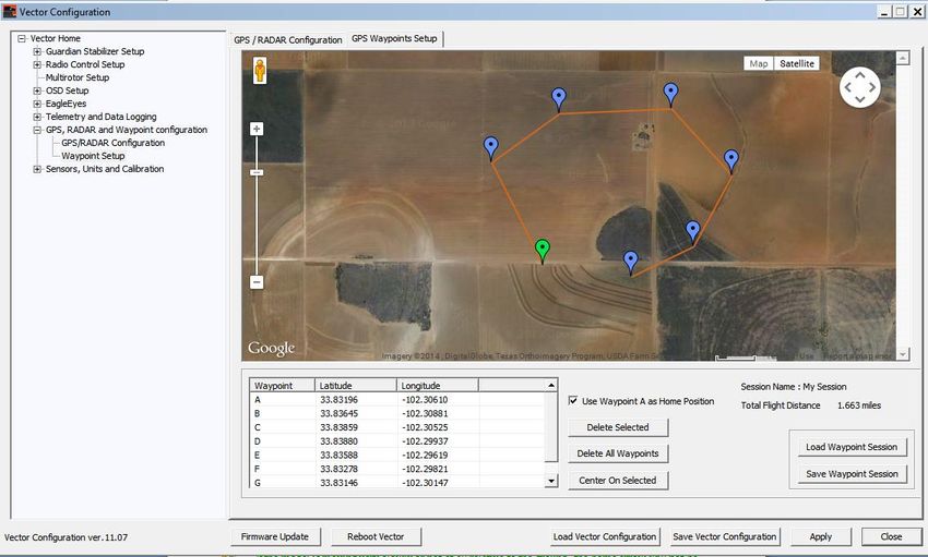
USER GUIDE
        6.3.3 Optimal Fixed Wing leveling ............................................................................................................................................... 65
    6.4 .... Return to Home Testing and Operation ................................................................................................................ 65
        6.4.1 RTH Limitations........................................................................................................................................................................ 65
        6.4.2 RTH Ground Testing ............................................................................................................................................................... 65
        6.4.3 In-air RTH Testing ................................................................................................................................................................... 66
7             Advanced Vector Setup and Calibration....................................................................................................... 66
    7.1 .... Advanced OSD Setup ...................................................................................................................................................... 66
        7.1.1 The Advanced Numeric Readouts Menu ....................................................................................................................... 66
        7.1.2 Gauges and Swatches ............................................................................................................................................................. 67
        7.1.3 The Advanced Graphics/Indicators Menu .................................................................................................................... 69
    7.2 .... Using Optional RPM and Temperature Sensors ................................................................................................ 69
        7.2.1 Temperature Sensor ............................................................................................................................................................... 69
        7.2.2 Brushless RPM Sensor ........................................................................................................................................................... 69
    7.3 .... Waypoints ........................................................................................................................................................................... 70
        7.3.1 Configuring Waypoints .......................................................................................................................................................... 70
        7.3.2 Showing Waypoints on the OSD ........................................................................................................................................ 71
    7.4 .... Data Logging ..................................................................................................................................................................... 71
        7.4.1 Configuring Data Logging ..................................................................................................................................................... 71
        7.4.2 Downloading, Viewing and Saving Logged Flight Information ........................................................................... 72
        7.4.3 Additional Data Logging and Telemetry Features .................................................................................................... 73
    7.5 .... Advanced RTH Setup...................................................................................................................................................... 73
        7.5.1 Home Altitude Mode ............................................................................................................................................................... 73
        7.5.2 Other Advanced RTH Settings ............................................................................................................................................ 74
    7.6 .... Acoustic Variometer ....................................................................................................................................................... 74
    7.7 .... Vector Calibration ........................................................................................................................................................... 75
        7.7.1 Electrical Calibration .............................................................................................................................................................. 76
        7.7.2 Altimeter Calibration.............................................................................................................................................................. 76
    7.8 .... GPS Configuration ........................................................................................................................................................... 77
        7.8.1 Choosing the GPS Position Display Format .................................................................................................................. 77
        7.8.2 Changing the GPS Fix Quality Settings ............................................................................................................................ 77
8             Troubleshooting ..................................................................................................................................................... 78
9             Notification Messages .......................................................................................................................................... 81
10            Description of Numeric Readouts ................................................................................................................... 86
11            Regulatory ................................................................................................................................................................ 88
12            Limited Warranty .................................................................................................................................................. 89

                                                                                                                                                                                                            v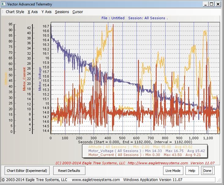
USER GUIDE
1 Safety
The Vector is intended to be used exclusively for recreational purposes in model planes, boats and cars. Using
the Vector for other purposes is not supported. Further, using the Vector in situations where its use or failure
could result in loss of life, bodily injury or property damage is expressly prohibited.
Eagle Tree Systems, LLC, is not responsible for your use of this product, or for any damages or injuries
you may cause or sustain as a result of its usage.
1.1 Read the Manual!
This manual contains important instructions related to safety. Read the entire manual before proceeding, to
become familiar with the features and operation of the Vector. Failure to correctly configure or operate the
Vector could cause damage to personal property or serious injury!
The latest version of this manual is available in the Product Manuals section of the Support tab on
http://www.eagletreesystems.com.
If, after you read the manual, you have further questions or problems, see the “How to Get Help” section below.
Reading this manual is probably more enjoyable, and will probably take less time, than rebuilding your
model!
1.2 Special Symbols used in the Manual
Warning that could affect safety or result in injury, a crash, property damage or Vector hardware
damage if not heeded.
Under construction. This feature is experimental, incomplete, or under active development.
Information applicable only for fixed wing models
Information applicable only for multirotor models
Helpful Note or Tip
1.3 General Safety Precautions
In addition to other warnings and other precautions in this manual, the following should always be
observed:
The Vector is intended for recreational use only, in model aircraft. Any other use is not supported.
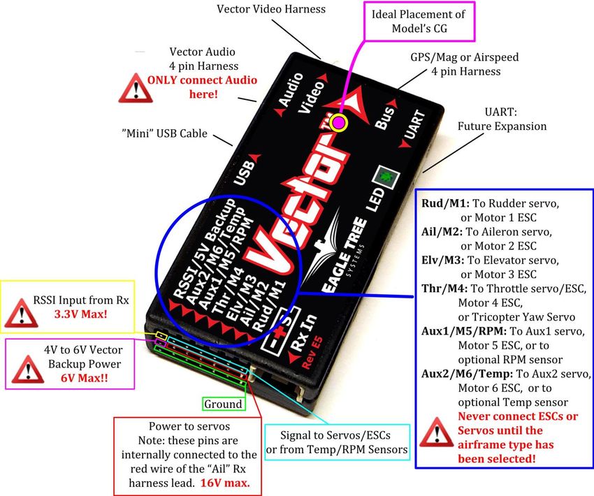
Never connect ESCs or servos to the Vector until you have verified the airframe type is correctly
selected! Doing so can cause multirotor propellers to spin at high speed, or can destroy fixed wing
servos.
Always remove propeller(s) or otherwise disable motor(s) when configuring the Vector!
Always move a safe distance away from the model before starting the motor(s), and never approach the
model with the propeller(s) spinning! Never approach a multirotor when it is armed!
Always wear eye protection when operating models with propellers!
6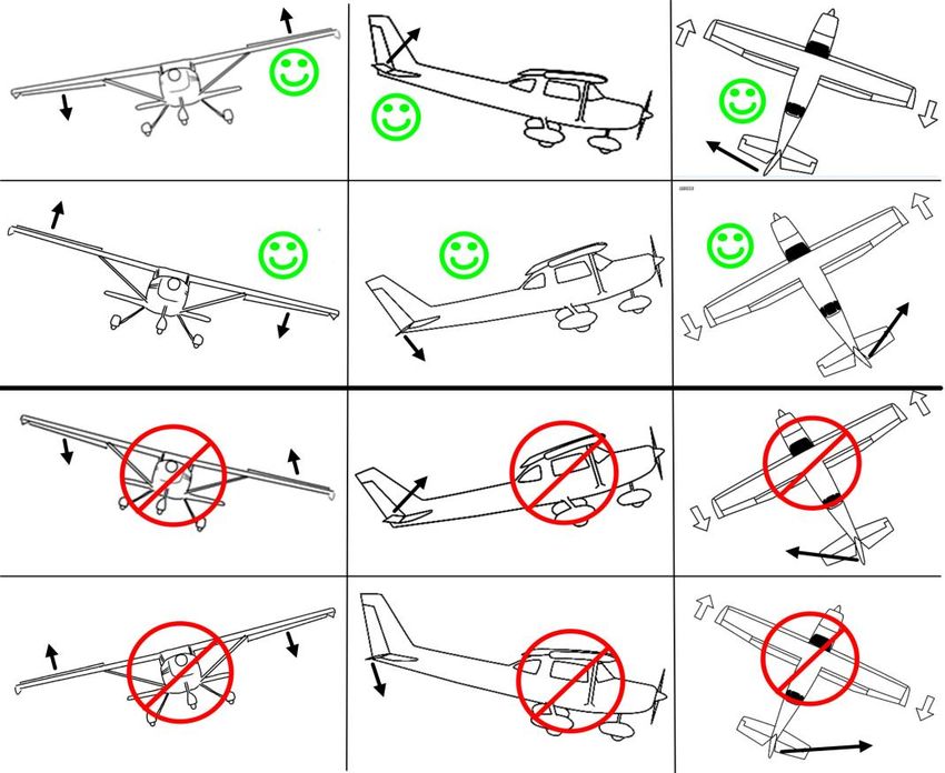
USER GUIDE
RC models and accessories are not toys! The Vector should not be used by children.
You should always use a spotter if your eyes are not on your model. For USA customers, please refer
to the Academy of Model Aeronautics Safety Code at http://www.modelaircraft.org/files/105.PDF and
FPV related code at http://www.modelaircraft.org/files/550.pdf
Always obey the law when flying. Most video transmitters used for FPV flying require an amateur
radio license to operate legally.
If you have never set up or operated an RC model before, you will need help from an experienced
modeler. Local RC clubs are great ways to meet experienced modelers, and receive the required
training. This requirement is especially true for FPV flying, which can be more challenging.
Never operate your model aircraft near or over buildings, power/telephone lines, or other obstacles.
Never operate your model aircraft near or over people or animals! Never operate your model after
consuming drugs or alcohol!
Never operate the Vector in a situation where it may get wet, such as on a rainy day.
Do not change wiring in your model when any power is applied.
2 Overview
2.1 Introduction
Thank you for your purchase! Based on Eagle Tree's proven inertial stabilization and video technology, the
Vector Flight Controller + OSD has everything we’ve dreamed about, in one small, lightweight, easy to use
product:
Straightforward to set up and operate "out of the
box" with no PC required
FIXED WING and MULTIROTOR Flight Controller
with GPS modes and RTH
Built-in OSD with COLOR GRAPHICS
OSD display is fully configurable, so you can make
the screen as simple or detailed as you want it
OSD still displays even if your camera fails!
COMPATIBLE: PCM, SPPM and S.BUS™ receiver
support, with several types of RSSI
EXPANDABLE with additional sensors,
accessories, and internet firmware updates
FLEXIBLE: fly with or without your FPV equipment
Built in FLIGHT DATA RECORDER helps take the guesswork out if something goes wrong
REDUCED WIRING: innovative wire harness with power distribution simplifies hookup
Built-in altimeter, IMU, and magnetic compass sensors
Current sensor with quiet and efficient Power Supply Unit supports up to 6S packs
7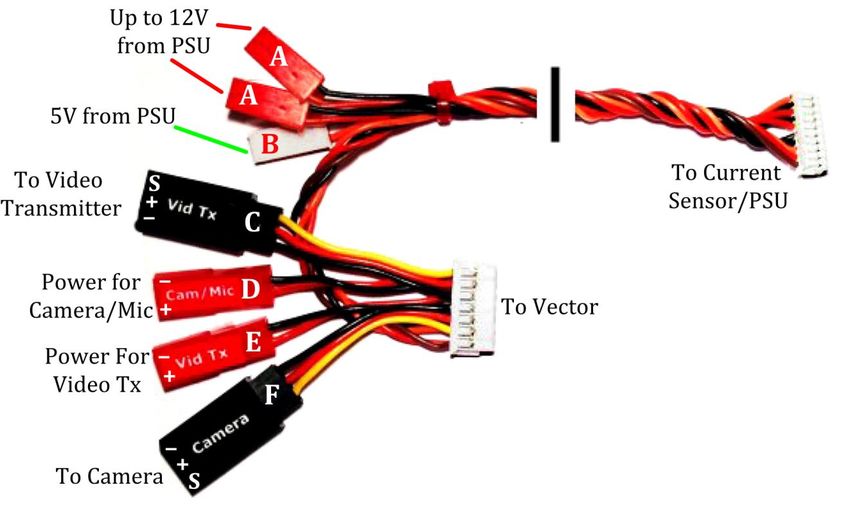
USER GUIDE
2.2 Packing List
Your package should include the following:
Vector Controller
Current Sensor/PSU (DeansTM, XT60TM or wire leads version),
GPS/Magnetometer (GPS/Mag), with GPS stand, clip and screw
Video, Audio (not shown), GPS, and Receiver Harnesses
2.3 Specifications
Supported Airframes:
o Traditional fixed wing, Elevon, and V-tail planes
o Tricopter, Quadcopter, and Hexacopter multirotors
Recommended Airframes: the Vector is not recommended for large or heavy airframes, due to no or
limited testing on these types of models at this time. Examples: giant scale fixed wing models, gas or
nitro models, turbines, or multirotors larger than 650mm are not recommended.
Video formats: composite NTSC and PAL (autodetect)
Servo/ESC Output framerate:
o Fixed wing: adjustable up to 400Hz
o Multirotor (including tricopter yaw servo): 400Hz
Dimensions (L x W x H, approximate):
o Controller: 65mm x 33mm x 14mm
o GPS/Mag: 35mm x 24mm x 15mm
o Current Sensor/PSU (with Deans™): 42mm x 19mm x 18mm
Mass (approximate):
o Controller: 21g
o GPS/Mag: 13g
o Current Sensor/PSU (with Deans™): 15g
Current Sensor/PSU
o Peak measured current: 140 amps (see section 3.4)
o Max pack voltage: 6s/25.2V
o Maximum 12V PSU current: 1A
o Maximum 5V PSU current: 1A
8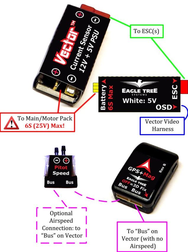
USER GUIDE
2.4 How to Get Help and Request New Features
Eagle Tree is committed to providing great customer service. Once you’ve read the manual, if something is not
clear, just ask. We’d much prefer to take the time to answer your questions, rather than having you waste your
valuable time struggling with an issue.
To get help 24/7, visit the Eagle Tree Vector support thread on RCGroups:
http://www.rcgroups.com/forums/showthread.php?t=2032857
Or, visit the thread on FPVLab:
http://fpvlab.com/forums/showthread.php?22260
Chances are someone has posted a solution to your problem already. If not, posting your problem on the forum
will get a very quick response from the Eagle Tree community.
If you prefer to not post on the forum, or you feel there is a problem with your Eagle Tree hardware, please
open a support ticket with us at http://ticket.eagletreesystems.com and we will respond to your support ticket
as soon as we can – normally within a few business hours. Note that when you create a support ticket, you
will be emailed a link that will let you check the status of the ticket. If you do not receive the email, most likely a
spam filter is intercepting emails from Eagle Tree.
Also, Eagle Tree greatly values your feedback on how we can improve our products. To leave us feedback for a
new feature request or improvement, post the feedback on our support threads above, create a support ticket
with your feedback, or just email us at support@eagletreesystems.com.

2.5 Installing the Software, and Updating the Firmware
To configure your Vector with the software, or to update the Vector firmware, you
will need to install our software on a compatible device.

Additionally, you will need a standard “mini” USB cable. You probably have one of
these cables already, but if not, you can order one online from us, or elsewhere.
Our p/n is USB-CAB-MINIB.

2.5.1 Software Compatibility
The software is compatible with Windows XP, Vista, Windows 7, and Windows 8/8.1. Most Windows based
PCs, laptops, notebooks, and tablets (including the Surface™ Pro™) are compatible with the software.

A minimum screen resolution of 1024x768 is required.

If you have a Mac™, you can run our software by using a correctly configured Windows emulator such as
VMWare™.

2.5.2 Downloading the Latest Software
The latest software for the Vector is available online at no
additional charge, by selecting “Download Latest Software”
from the Support tab at http://www.eagletreesystems.com
and selecting the Vector software.

The software version you are presently running is shown in
the lower left hand corner of the software. If that version
is lower than the version presently on our website,
consider upgrading.
                                                                                                                      9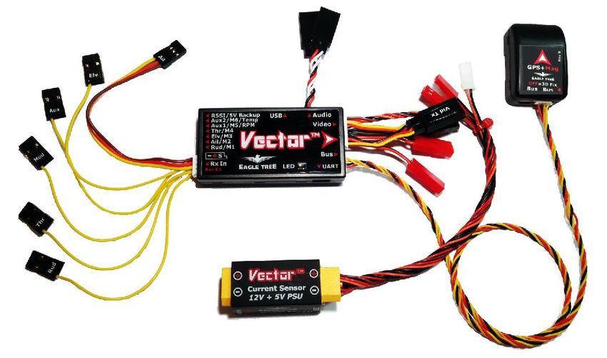
USER GUIDE
2.5.3 Updating your Vector Firmware
Even if you will be configuring the Vector using the stick menus, it’s a good idea to keep your Vector firmware
updated, in case we add a feature or resolve an issue that is relevant to your airframe. Our latest software
always has the latest Vector firmware included with it.

To check to see if you have the latest firmware, first check
what firmware version is installed on your Vector, which is
displayed at the bottom of the Vector boot-up OSD screen.
Or, you can check the version by using the firmware update
utility described below. Then, compare your version
number with the latest Vector firmware version we have
released (listed on the software download page on our
website).

To update the Vector firmware, install the latest software,
connect the Vector to USB, click the “Firmware Update”
button in the software (in the bottom row of buttons), and
follow the instructions.

       Make sure that your GPS/Mag is connected to your Vector before updating firmware. The firmware on
the GPS/Mag will also be updated automatically, if needed.
Also, note that if you install new software and it detects that the Vector’s firmware needs an update, it will
automatically run the firmware update utility.

2.6 Getting Notified about Important Vector Updates
Eagle Tree updates the Vector firmware and software periodically to add new features or to address issues that
may arise, and will issue important hardware information bulletins as needed. There are two ways to get
notified about these:

1) Subscribe to the Vector update notification thread on RCGroups. Whenever we update the software or
   release a hardware bulletin, we will post a note to this thread, and subscribing to it should result in you
   receiving an email. Note that this thread will normally be closed, so only we can post to it, reducing the
   number of emails you will receive.

http://www.rcgroups.com/forums/showthread.php?t=2159747

2) Follow us or like us on Facebook™. We will post a note on Facebook indicating that new software or
   important hardware information has been posted, and you should see that on your Facebook page.

http://www.facebook.com/eagletreesystems

                                                                                                                 10
USER GUIDE
2.7 Glossary of Terms used in the Manual
Here are definitions for some of the terms used throughout the manual.
FPV – FPV stands for First Person View. If you are not familiar with FPV, there are many websites devoted to
it. Our FPV overview web page at http://www.eagletreesystems.com/OSD has a brief tutorial on FPV, which is
a good place to start.
OSD – OSD stands for On Screen Display. The OSD shows flight information, overlaid on the video camera
image.
RTH – Return to Home. The Vector can optionally return your model to the home point if R/C link is lost.
Software – the term “software” in the manual refers to our Windows PC software application.
Firmware – the firmware is the code that runs on the Vector itself. The latest Vector firmware is included
with the software.
Flight Controller or Stabilizer – the aspect of the Vector that stabilizes your model during flight
Pitch – Lift or descent of the nose and tail of the
model (front to back tilt on multirotors). Normally
controlled by the elevator, or movement of elevons in
same direction.
Roll – Rocking movement of the wings, side to side
(side to side tilt on multirotors). Normally controlled
by ailerons, or movement of elevons in opposite
directions.
Yaw – Turning of the airplane without banking
(rotation on multirotors). Normally controlled by
the rudder.
Axis – an imaginary line drawn horizontally through
your model’s wing (for Pitch), horizontally through your fuselage (for roll), or vertically through the center of
your fuselage (for yaw).
Gain – a setting that controls how hard the stabilizer works to hold the orientation of the model around a
certain axis.
Oscillations – rapid swings of your model around one of its axes, due to a gain setting being too high.
Mode 2 Radio: Transmitters with rudder and throttle on the left stick, and aileron and elevator on the right
stick.
Control Stick – The stick on Mode 2 radios that controls elevator and aileron functions (pitch and roll).
Attitude – The orientation of the model with respect to the horizon.
2D Mode – A mode where the model is brought to a level attitude (level flight and level wings) by the Vector
when the control stick is centered.
3D Mode – A mode where the Vector attempts to hold the model’s present attitude when the control stick is
centered, by moving the model’s control surfaces automatically.
Gyro Mode – A mode where the stabilizer responds similarly to having gyros installed on the control surface
outputs.
Heading – The present direction of travel of the model with respect to North.
Control Surfaces – Your model’s elevator, ailerons (or elevons), flaperons, and/or rudder (if equipped).
11USER GUIDE
Mode Switch – A two or three position switch on your radio transmitter which you have configured to control
the “Mod” input on the Vector’s Receiver Connection Harness.
Toggle – One fairly rapid movement the Mode Switch between its extents. (UP/DOWN or DOWN/UP)
Configuration Gestures – A series of toggles of the Mode Switch. The number of times you toggle the switch
determines which configuration step is performed.
PSU - Power Supply Unit. This refers to the 5V and 12V switching regulators built into the Vector current
sensor.
Toilet Bowl – When a multirotor is hovering, the condition of orbiting around the desired hover point,
sometimes in an ever increasing diameter, due to compass error or other issues.
12USER GUIDE
3 Connecting the Vector
This section describes the Vector’s cabling and
connections, and how to connect the Vector to your
RC receiver, your servos or ESCs, and your FPV video
transmitter and camera.
3.1 Vector Controller Connections
The figure below shows the function of each of the
Vector’s ports, and other Vector information.
3.1.1 Backup Power
If you want the Vector to use a redundant power supply for safety, the middle pin of the RSSI/5V Backup
connection can be used to supply backup power to the Vector. Normally the Vector is powered by 5V from the
Current Sensor/PSU, but the Vector will take power from the backup connection whenever the voltage at this
pin is approximately 0.5V higher than the voltage coming from the Current Sensor/PSU.
13USER GUIDE
For example, if the backup power is connected to the BEC of your ESC (via your receiver), and that is supplying
5.0V, the Vector will use the PSU power unless the PSU voltage drops below 4.5V. Likewise, if your BEC is
providing 6.0V to the backup power port, the backup power port will always be powering the Vector unless the
BEC output fails.
Note that the backup power input will NOT power your camera or video transmitter. Only the Vector
and accessories connected to the “Bus” port will be powered.
3.2 Vector GPS/Mag and Current Sensor/PSU Connections
Connections to the Current Sensor/PSU (DeansTM version shown), the GPS/Mag, and the optional Pitot Airspeed
sensor are shown in the figure below.
The “Bus” connectors on the GPS/Mag
and Airspeed sensors are internally connected
together. Wiring order, or which of the two
connectors on each sensor is used, does not
matter.
In other words, you can plug into either “Bus”
connector, and if you “daisy-chain” the
Airspeed with the GPS/Mag, either unit can be
at the head of the chain.
Never connect the GPS/Mag or pitot
sensor to the Vector’s AUDIO
connection. Doing so will destroy the sensor!
14USER GUIDE
3.3 Vector Current Sensor/PSU Power Output
The Vector’s high efficiency and low noise PSU accepts up to 6S voltage input, and provides filtered 5V and up
to 12V output at 1A max per channel. It's perfect for powering most FPV gear, and can also power your receiver
on multirotors (when NO servos are being powered by the RX!), eliminating the need for an external BEC.
Never use the PSU to power any servos on your model! The PSU can shut off due to excessive power
draw, causing a crash! Servos MUST be powered by a stand alone BEC, a BEC built into your ESC, or a
separate radio flight pack!
Note that the 12V regulator does NOT boost the voltage, like a SEPIC. However, the Vector's 12V PSU has a
unique Low Voltage Loss feature that drops the regulator’s output by only about 0.5V if you are using a 3S
pack operating below 12.5V. For example, if your 3S pack is at 11.5V, the regulator outputs about 11V. Other
non-boost switching regulators typically drop the output voltage by 1.3V or more.
SEPIC and other voltage boost regulators are generally much less efficient and generate much more UHF band
noise, and in many cases you don’t need one. You never need one if your pack is 4s or above, and all known
cameras and many transmitters will operate well across the 3S pack voltage range. Typically, 1.3GHz
transmitters may provide reduced power output with less than 12V voltage, and 5.8GHz transmitters work fine
at less than 12V. Be sure to check your transmitter manual’s specs to determine this. If your transmitter does
need a boost when operating at the lower end of 3S, a JST equipped boost regulator can easily be connected
into the Vector's video harness (between connections “A” and “E” in the video harness drawing below).
3.4 Current Sensor Maximum Continuous Current, and Load Testing
The current sensor’s continuous current capability depends on the type of connectors/wires you are using, and
other factors.
If your model draws a large amount of current (greater than approximately 60 amps continuous) make sure
you verify that your power system, including the current sensor, can handle your worst case continuous
current load.
In high current applications it is recommended (if you can do so safely) that you run your model in an extended
stationary “bench” test, similar in duration and power usage to your most aggressive modeling, to ensure there
are no problems with any connections, wiring doesn’t get too hot, etc. DO NOT OPERATE YOUR MODEL IF
YOU HAVE PROBLEMS DURING THIS EXTENDED STATIONARY TEST!
It is also recommended that the current sensor be mounted so that airflow is directed through one of the
openings of the sensor.
Never exceed the manufacturer’s continuous current rating for the types of connectors installed on your
current sensor! If the current sensor or wiring becomes too hot during flight due to too much current,
the connectors can fail, or the PSU can shut off, causing a crash!
Make sure that the connector contacts on your current sensor and mating connectors are not damaged or
weakened. A damaged or weakened contact can potentially fold over and short when connected, or cause
intermittent in-flight failures!
15USER GUIDE
3.5 Vector Wiring
The Vector’s wire harnesses are shown below. Note that
a set of replacement wire harnesses is available (p/n VEC-
CAB-SET). Having additional sets make it easier to move
your Vector from model to model.
Video Harness – routes video signals, and provides
power from the Current Sensor/PSU to the Vector, and
optionally to your video transmitter, camera, and
microphone.
Audio Harness – this cable connects to your microphone,
and also to the audio output of your video transmitter.
Receiver Connection Harness – this cable connects
between the Vector and your RC receiver/LRS.
GPS Harness – this cable connects between the Vector and the GPS/Mag.
3.5.1 Vector Video Harness + Connecting your Video Camera and Transmitter
The Vector's innovative video harness makes it easy to connect your 5V or 12V cameras and transmitters
without keeping an electrician on standby. The figure below shows a typical hookup, with a 12V camera, 12V
transmitter, and a microphone.
16USER GUIDE
The first step to wiring your camera and transmitter is to install servo connectors on the wire harnesses that
came with these components, if they don’t have them already. Servo connectors and crimpers are available
online or at your local hobby store. Either Futaba™ or JR™ style connectors will work.
Refer to the figure at right.
Consult the manuals for your
camera and video transmitter,
identify the signal, power and
ground wires, and install the servo
connectors on these wires.
Alternatively, FPV shops like
http://www.readymaderc.com
supply Vector compatible servo
adapter cables for most cameras
and video transmitters.
Make sure the polarity of the servo connector is correct, so that the “S, + and –” pins of the connector
align correctly the “S, + and –” pins of the mating female connector on the video harness!
If you are using a camera with a built-in battery, such as a GoPro™, the power servo lead does not need
to be connected.
Referring to the video harness diagram below, connect the camera’s servo connector to camera connector “F”,
and the video transmitter’s servo connector to transmitter connector “C” on the video harness.
Inside the Vector, the red wire of the camera power connector “D” is internally connected to the red
wire of the camera connector “F”, and the red wire of transmitter power connector “E” is internally connected
to the red wire of transmitter connector “C”. Also, all ground (black) wires are internally connected in the
Vector.
3.5.2 Providing power to your Video Transmitter and Camera
Powering your video equipment is typically very easy with the Vector.
17USER GUIDE
Here are typical wiring strategies, depending on the number of batteries desired, transmitter and camera
voltages, etc.
Video Setup Wiring Method
Single Battery, 12V Connect both red PSU power taps “A” to camera and transmitter power inputs “D”
camera, 12V transmitter and “E”
Single Battery, 5V Connect the white PSU power tap “B” to camera power input “D”. Connect a red
camera, 12V transmitter PSU power tap “A” to transmitter power input “E”.
Single Battery, 12V Connect the white PSU power tap “B” to transmitter power input “E”. Connect a
camera, 5V transmitter red PSU power tap “A” to camera power input “D”.
Single Battery, 5V Construct or purchase a JST Y cable. Connect the female end of the Y cable to the
camera, 5V transmitter white PSU power tap “B”, and connect the two male ends of the Y cable to
transmitter power input “E” and camera power input “D”.
Separate Video Connect video battery(s) of appropriate voltage(s) to camera power input “D”
battery(s) and/or transmitter power input “E”. Note that if you want to use one video
battery for both camera and transmitter, a JST Y cable will be needed.
Make sure that you do not make a mistake in the wiring that causes 12V power to be used with a 5V
camera or transmitter! This will likely destroy the camera or transmitter.
Remember that if you use a 3s or lower pack, the 12V power taps will provide a voltage that is about
0.5V less than the present pack voltage. If your video transmitter reduces output power with voltages less
than 12V, and you need maximum range, you will need to insert a “boost” or “SEPIC” regulator between the
power tap “A” and the transmitter power input “E”, or use a separate video battery.
Never exceed the 1 amp current limit for either the 5V tap or the 12V taps. The affected voltage
regulator may shut off if this is exceeded, which can cause the Vector to turn off during flight if the 5V
regulator is affected, as well as shutting off the affected video equipment! Never use the taps for powering
equipment other than your video equipment!
Normally, only extremely high power video transmitters would exceed 1 amp, but check your video equipment
manual.
It is ok if you draw up to 1 amp from the 5V regulator and up to 1 amp from the 12V regulator
simultaneously.
3.5.3 Vector Audio Harness and Audio Connections
If you do not want to hear Vector voice alerts or the acoustic variometer, it is not necessary to use the audio
harness, so this step can be skipped.
Refer to the figure:
To hear voice alerts or the acoustic variometer from the
Vector, connect the audio harness to the Vector’s Audio
connector, and connect your video transmitter’s audio
in servo connector (described above) to the “Tx Audio”
connector on the audio harness.
To use an external microphone in this configuration, connect the microphone to the audio harness “Microphn”
connector, paying attention to the correct pinout.
18USER GUIDE
Note that the voltage supplied to the red wire of the “Camera/Mic” power input connector “D” on the
video harness will be supplied to the red wire on the “Microphn” audio harness connector.
3.5.4 Vector Receiver Harness
The Receiver Harness is used to connect the Vector to the outputs of your receiver. The pin-out for the
Receiver Harness is shown below.
Do not power your receiver with a voltage higher than 16V.
The Vector does not power your receiver or servos. You will need to power your receiver and servos
as you would in a non-Vector model, such as with a stand-alone BEC, a BEC built into your ESC, or a separate
battery pack.
Whatever power is provided to your receiver will be routed through the Vector to your servos. Whatever
power is provided by an ESC’s BEC will be routed through the Vector to your receiver and servos.
You can alternatively use the 5 volt tap from the PSU (if not being used to power a 5 volt camera or video TX) to
power your receiver on multirotors. Please see section 3.5.6, “Powering your Receiver on Multirotors" for
additional info.
Three types of receiver inputs are supported with the Vector:
Traditional (parallel): each of the relevant harness connections needs to be connected to the appropriate
output port on the receiver. See section 3.5.7 below for information on connecting the receiver harness inputs
to your receiver.
Serial PPM (SPPM) and S.BUS™ (serial modes): only the “Ail” connector of the receiver harness should be
connected to the SPPM or S.BUS™ output of your receiver. Your receiver’s outputs are programmed in the
Vector, as described later.
Note: Connect only the “Ail” wire to your receiver when using a serial mode. Never connect other wires from
the receiver harness to your receiver if you are using a serial mode!
To reduce wiring, if you use a serial mode you can use a needle or small probe to carefully pry up the
tabs of the other connections of the receiver harness, remove the unused wires, and save them for later use. Or,
just trim off the extra wires.
19USER GUIDE
3.5.5 Receiver Connection Harness Load Capacity (Fixed Wing Only)
With typical fixed wing electric model wiring, the ESC’s BEC is connected to the Vector’s throttle output
channel. This BEC powers the servos, and all servos are connected to the Vector’s servo outputs. If you
have this configuration, please skip this section.
Also, skip this section if you do not have large servos, or if the BEC or battery powering your servos is rated at 6
amps continuous or less (the vast majority are).
If, however, the AIL lead of the Vector’s receiver connection harness takes power from your receiver, and this
powers large servos you have connected to the Vector, OR, you have large servos connected to both your
receiver and the Vector, please read the following:
You should not allow more than 6 amps continuous current to flow through the AIL wire.
Note also that the AIL lead of the harness should not be excessively warm after flying, which could indicate that
too much current is passing through it.
If your configuration could result in more than 6 amps continuous current flowing through the AIL wire, there
are two ways to supply additional power to your servos:
If you are not using all the servo output connections on your Vector, a male to male servo wire (with
the signal line cut!) can be connected between a free servo channel on the Vector, and a free channel on
your receiver.
If all the servo connections on the Vector are being used, a male/male/female Y cable (ET p/n CAB-Y-1
or similar) with the signal line cut can be used to provide additional power to the servos, as shown in
Figure 3.
3.5.6 Powering your Receiver on Multirotors
Voltage from the 5V tap “B” can normally be used to power your receiver on multirotors, eliminating
the need to have an additional BEC. One way to do this, assuming the 5V tap is not being used for your camera
or transmitter, is to connect a female JST to male servo adapter cable from the 5V tap to a spare receiver
channel. If the 5V tap is already being used, you will need a Y cable to do this.
However, remember that power will go from your receiver to the Vector’s servo outputs, via the red wire of the
“Ail” connector on the Vector receiver harness. If your ESCs are not optoisolated from their receiver inputs,
this voltage will power the ESCs even if the ESC main power connector is not plugged into the Current
Sensor/PSU. If your ESCs produce startup tones when the receiver is powered from the Vector, but the ESC
main power connector is not plugged into the Current Sensor/PSU, the ESCs are not optoisolated.
20USER GUIDE
In this case, it’s important that you make sure you never arm your multirotor when the main ESC power
connector is disconnected from the Current Sensor/PSU. Or, you can address this issue in some other ways:
a) remove/disconnect the red wire from the “Ail”
connector, so that power will not pass from
your receiver to the ESCs when using the 5V
tap to power your receiver.
b) Or, remove/disconnect the power servo wire
from each ESC. This may be required anyway,
as some non-optoisolated ESCs could be
damaged if the red wires are connected
together.
c) Or, be sure to never connect your main pack to the current sensor without having the ESC main power
connector also plugged into the current sensor.
If one of these steps is not followed, your ESCs will receive power even when the ESC main power
connector is not plugged into the current sensor. This can cause at least two potential problems if you
arm the multirotor in this condition:
The propellers can spin even though the main pack is not connected to the ESCs!
With some ESCs, a brownout can occur in this condition that has been known to cause these ESCs to
reprogram their endpoints. This can lead to unpredictable results such as propellers spinning at
different speeds after arming, possibly creating an unsafe condition!
21You can also read