Zippie Salsa/Salsa M Directions for use
←
→
Page content transcription
If your browser does not render page correctly, please read the page content below
Powered Wheelchair

                       Directions for use

Zippie Salsa/Salsa M

                                            035005.UK
User Information
                                                                   IMPORTANT:
Intended use power wheel chairs:
Power wheelchairs are exclusively for a user who is unable                   DO NOT USE YOUR WHEELCHAIR UNTIL
to walk or has limited mobility, for their own personal use                  THIS MANUAL HAS BEEN READ AND
in- and outdoor.                                                             UNDERSTOOD.
When an Attendant Control Module is fitted, the Power
Wheelchair may be operated by an assistant on behalf of
the user.
When a Dual Control Module is fitted the Power
Wheelchair may be operated by the user, or control may
be switched to an assistant to operate on behalf of the
user.
                                                                   Sunrise Medical declares under its sole responsibility that
The maximum weight limit (includes both the user and any           this product is in conformity with the requirements of the
weight of accessories fitted to the wheelchair) is marked          directive 93/42/EEC amended by 2007/47/EEC.”
on the serial number label, which is affixed to the chassis
of the chair.                                                      Sunrise Medical declares that this product fulfils the
The chair serial number is affixed also to the front page of       performance requirements for a “Crash Test” to
the owners manual supplied with the wheelchair.                    ISO 7176-19.

Warranty can only be issued if the product is used under           Its high level of flexibility, due to the number of possible
the specified conditions and for the intended purpose.             adjustments, and the modular platform technology
                                                                   (modular construction system) make the Zippie Salsa M
The intended lifetime of the wheelchair is 5 years. Please         / Salsa ideal for re-use.
DO NOT use or fit any 3rd party components to the
wheelchair unless they are officially approved by Sunrise          Individual modules (seat tilt in space, backrest angle
Medical.                                                           adjustment) can be fitted and removed very quickly and
                                                                   within the seating system there are a range of possibilities
Area of application                                                so that individual adjustments can be made to suit the
                                                                   end user.
The varieties of fitting variants, as well as the modular
design, mean that it can be used by those who cannot               The Serial Number and other important information may
walk or have limited mobility because of:                          be found on a label situated on the right-hand side, main
                                                                   frame of the product.
•        Paralysis                                                 In addition, further serial number labels are placed on
•        Loss of extremity (leg amputation)                        any modules and also on this Owners Manual.
•        Extremity defect deformity
•        Joint contractures/joint injuries
•        Strokes and brain injuries
•        Neurological disabilities (e.g. MS, Parkinson…)
•        Illnesses such as heart and circulation deficiencies,
         disturbance of equilibrium or cachexia as well as for
         elderly people who still have the strength in the upper
         body.
•        Persons who are mentally and physically able to
         control an input device to operate the chair and its
         functions in a safe way.

When considering provision, please also note the body
size, weight including the distribution of body weight, the
user’s physical and psychological constitution, the age of
the user, their living conditions and their environment.
If in doubt a health care professional should be involved
to ensure the user is not exposed to unacceptable risks.

Sunrise Medical is ISO 9001 certified, which ensures
quality at all stages of the development and production of
this wheelchair.

2   ZIPPIE SALSA & SALSA M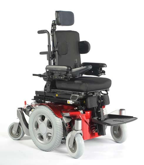
1.0 Your Wheelchair	                              6   6.10 Back Height Adjustment 	                                    33
2.0 How to use this manual	                       6   6.11 Manual setting of the seat angle	                           35
                                                       6.12 Headrest	                                                   36
2.1 Introduction	                                 6   6.13 Powered Seating	                                            36
2.2 Guarantee	                                    6
                                                       7.0 The VR2 Hand Control Series 	                                38
2.3 Warranty conditions	                          6
                                                       7.1 VR2	                                                         38
3.0 Label Explanation / Word definitions	         7
                                                       7.2 VR2-L	                                                       40
3.1 Definitions of words used in this manual	     7   7.3 VR2 Dual control unit	                                       41
3.2 Label explanations	                           8
                                                       8.0 Troubleshooting Using The VR2 	                              43
4.0 General safety warning and user tips	        10
                                                       9.0 Control mounts	                                              45
4.1 General warnings	                            10
4.2 Features and options	                        10   9.1 General warnings	                                            45
4.3 Kerbs	                                       10   9.2 Attendant control	                                           45
4.4 Routine service	                             10   9.3 Parallel swing-away control	                                 45
4.5 Brake release	                               10
                                                       10.0 Batteries and charging 	                                    46
4.6 EMC - Radio transmitting devices.	           11
4.7 Emergency braking	                           11   10.1 Zippie Salsa batteries 	                                    46
4.8 Sharp turns	                                 11   10.2 Safety cut-outs	                                            48
4.9 Batteries	                                   11   10.3 General battery information	                                48
4.10 Tyres	                                      11   10.4 Maintenance free batteries	                                 48
4.11 Weight limit	                               12   10.5 Battery care	                                               48
4.12 Wheelchair motors	                          12   10.6 Maintenance free battery care plan	                         48
4.13 Hot surfaces	                               12   10.7 General charger information	                                49
4.14 Wheelchair range	                           12   10.8 Charger safety features	                                    49
4.15 Road use	                                   12   10.9 Connecting the charger and charging	                        49
4.16 Adverse conditions	                         13   10.10 Charger safety and caution notes	                          49
4.17 Ramps	                                      13   10.11 The range of your vehicle	                                 50
4.18 Transfer to and from the chair	             13   10.12 Common battery statements	                                 50
4.19 Lift and tilt modules	                      13   10.13 Battery warranty	                                          51
4.20 Anti-tip tubes	                             14
                                                       11.0 Transportation	                                             52
4.21 Use on a slope	                             14
4.22 Using a vehicle mounted passenger lift      14   11.1 Transportation warnings:	                                   52
4.23 Creep mode	                                 15   11.2 Occupant restraint instructions	                            53
4.24 Stability of your wheelchair	               15   11.3 Crash testing on the Zippie SALSA	                          54
4.25 Wheels	                                     15   11.4 The tie down label and placement	                           54
4.26 Rear view mirror	                           16   11.5 Securing the wheelchair into the vehicle                    55
4.27 Crutch holder	                              16
                                                       12.0 Maintenance and Cleaning	                                   56
4.28 Lights and indicators	                      16
4.29 Swing away tray	                            16   12.1 Tyre maintenance and pressures	                             56
4.30 Using a kerb climber	                       16   12.2 Tyre wear	                                                  56
4.31 Lap belt	                                   17   12.3 Drive wheel tyre repair	                                    56
4.32 VR2 Controller (Fig. 4.21)	                 18   12.4 Removing the castor wheel	                                  58
                                                       12.5 Cleaning your wheelchair	                                   59
5.0 Preparing your wheelchair for use 	          19
                                                       12.6 Inspection of the upholstery/seating	                       59
5.1 Handling the wheelchair	                     19   12.7 Cleaning seating	                                           59
5.2 Preparation for transportation or storage    19   12.8 Cleaning controls	                                          60
5.3 Re-Assembling 	                              20   12.9 Lighting bulb exchange procedure	                           60
5.4 Brake release	                               20   12.10 Electrical connections	                                    60
5.5 Drive wheel suspension 	                     21   12.11 How to connect the cables to the batteries                 60
5.6 Control joystick unit position	              21   12.12 Controller access	                                         63
5.7 Getting ready to drive	                      21   12.13 Storage	                                                   63
5.8 Armrests	                                    22   12.14 Authorised Sunrise Medical service agents                  63
5.9 Legrests	                                    27   12.15 Recommended maintenance routines                           64
                                                       12.16 Performance checks	                                        65
6.0 Seating	                                     29
                                                       13.0 Specification sheets 	                                      66
6.2 Seat cushions	                               30
6.3 Removable seat covers	                       30   14.0 Service History	                                            68
6.4 Standard backrest upholstery	                30
                                                       15.0 Disposal	                                                   68
6.5 JAY backrests	                               30
6.6 Seat height adjustment	                      30   16.0 ZIPPIE SALSA - SALSA M Battery Wiring  70
6.7 Seat width adjustment 	                      31
6.8 Seat Depth Adjustment 	                      32
6.9 Backrest Angle Adjustment 	                  32
                                                                                                  ZIPPIE SALSA & SALSA   3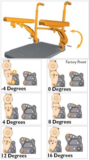
If you are visually impaired, this document can be viewed in
          PDF format at www.SunriseMedical.com or alternatively is
                      available on request in large text.
          For further information on the full specification and options and accessories
                                  please refer to the order form.
         All information is subject to change without notification. Please consult Sunrise
                               Medical with any queries you may have.

4   ZIPPIE SALSA & SALSA M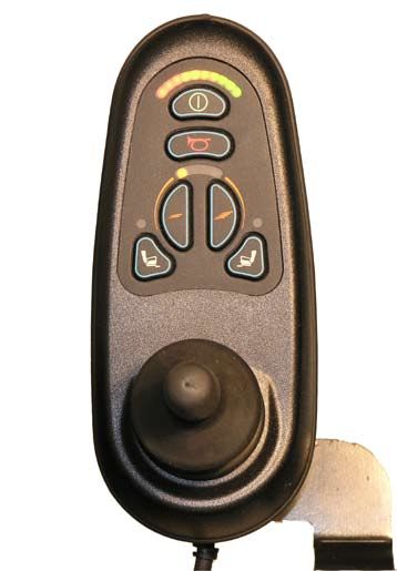
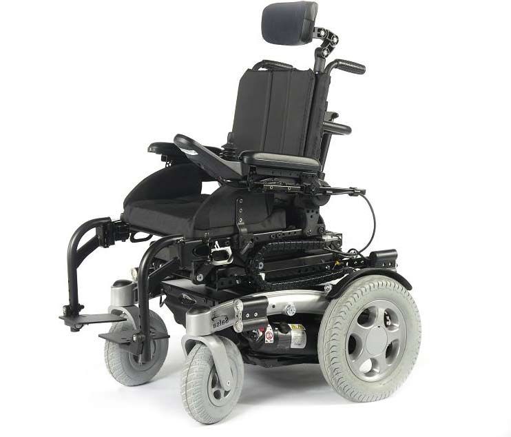
ZIPPIE SALSA M
                         Armrest

                                                      Controller

             Cushion

    Footrest

     Footplate
                                                            Rear wheel

                                             Front castor

ZIPPIE SALSA           Controller

                                              Armrest

         Cushion

  Footrest

                                                            Rear wheel

   Footplate

                                    Castor

                                                                   ZIPPIE SALSA & SALSA   5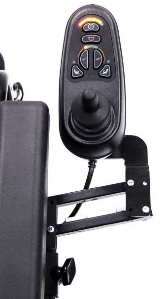
1.0 Your Wheelchair                                                2.0 How to use this manual

We at Sunrise Medical want you to get the best out of              2.1 Introduction
your ZIPPIE SALSA wheelchair. This Owner’s Manual will             Please keep a note of your local service agent’s address
familiarise you with the chair and its features. It contains       and telephone number in the space below.
hints on everyday usage and general care in addition to            In the event of a breakdown, contact them and try to give
information on the high quality standards which we adhere          all relevant details so they can help you quickly.
to and details about the guarantee.                                The wheelchairs shown and described in this user guide
                                                                   may not correspond in every detail exactly to your own
Your wheelchair should be delivered fully configured for           model. However, all instructions are completely relevant,
your use. There are a wide range of components and                 regardless of possible detail differences.
adjustments available on the ZIPPIE SALSA. For further             NOTE: The manufacturer reserves the right to alter without
information about these you should contact your Sunrise            notice any weights, measurements or other technical
Medical authorised dealer.                                         data shown in this manual. All figures, measurements and
Your wheelchair will reach you in excellent condition having       capacities shown in this manual are approximate and do not
been personally inspected before leaving our factory.              constitute specifications.
Following the guidelines for maintenance and cleaning
your wheelchair will maintain its first class condition and        2.2 Guarantee
give you complete satisfaction.                                    The guarantee form is included in the Sunrise Pack. Please
The ZIPPIE SALSA has been designed for use by an                   fill in the relevant details and return to us to register your
individual on a daily basis. It is suitable for both indoor        entitlement.
and outdoor use (Class B). It is only intended for use as
a pavement vehicle, but may also be used when crossing             THIS IN NO WAYAFFECTS YOUR STATUTORY RIGHTS.
between pavements.
                                                                   2.3 Warranty-Repair-Service Conditions
The wheelchair is to convey one individual person who              1) Repair or replacement is carried out by the authorised
has limited mobility with a max. weight of up to 75 kg; who        Sunrise Medical dealer.
has the cognitive, physical and visual ability to control the
wheelchair safely on a maximum slope of 14% (8°). If you           2) To apply the warranty conditions, should your wheelchair
are in any doubt as to the suitability of the power chair,         require attention under these arrangements, notify the
contact your local Sunrise Medical approved supplier for           designated Sunrise Medical service agent immediately
clarification, prior to commencing use.                            giving full information about the nature of the difficulty.
It is very important to read the relevant section of the owner’s   Should you be operating the Wheelchair away from the
manual when making any minor adjustments. Consult the              locality of the designated Sunrise Medical service agent,
Technical Manual or your local Sunrise Medical authorised          work under the “Warranty Conditions” will be carried out by
dealer for more complex adjustments.                               any other service agent designated by the manufacturer.
If you have any queries about the use, maintenance or safety       3) Should any part of the wheelchair require repair or
of your wheelchair, please contact your local approved             replacement, as a result of a specific manufacturing or
Sunrise Medical service agent. If you do not know of an            material defect, within twenty four months from the date
authorised dealer in your area or have any other questions         on which the possession of the wheelchair was transferred
please write or telephone:                                         to the original purchaser, and subject to it remaining within
Sunrise Medical Limited                                            that ownership, the part or parts will be repaired or replaced
High Street Wollaston                                              completely free of charge if returned to the authorised
West Midlands DY8 4PS                                              service agent.
England                                                            If you are unsure who your local servicing agent is:
Tel.: +44 (0) 1384446666                                           Please contact Sunrise Medical using the contact details
www.sunrisemedical.com                                             opposite.

                                                                    Dealer signature and stamp

6   ZIPPIE SALSA & SALSA M
3.0 Label Explanation / Word definitions
4) The guarantee also covers all repaired or replaced
parts for the remaining period of the guarantee for the        3.1 Definitions of words used in this manual
wheelchair.
                                                                     Word        Definition
5) Parts replaced after the original warranty has expired
are covered for a further twelve months.                                         Advice to the user of Potential Risk
                                                                   DANGER!       of serious injury or death if the
6) Items of a consumable nature will not generally be                            advice is not followed
covered during the normal warranty period, unless such
items have clearly suffered undue wear as a direct result
of an original manufacturing defect. These parts include,
amongst others, upholstery, tyres, inner tubes and similar                       Advice to the user of a potential risk
                                                                    WARNING!
parts. On powered products this will also include batteries,                     of injury if the advice is not followed
motor brushes etc.

7) The above warranty conditions apply to all wheelchair
parts for models purchased at full retail price.                                 Advice to user that potential
                                                                     CAUTION!    damage to equipment may occur if
8) Under normal circumstances, no responsibility will be                         the advice is not followed
accepted where the wheelchair has required repair or
replacement as a direct result of:
                                                                    NOTE:        General advice or best practice
  a) The wheelchair or part not having been maintained
  or serviced in accordance with the manufacturer’s
  recommendations, as stated in the Owner’s Manual                   RWD         Rear wheel drive
  and/or Service Manual. Or failing to use only the
  specified original equipment parts.                                MWD         Mid wheel drive

  b) The wheelchair or a part of the wheelchair was
  damaged through neglect, accident or improper use.                             Reference To Additional
                                                                                 Documentation
  c) Alterations to the wheelchair or parts, which are not
  in accordance with the manufacturer's specifications
  or the carrying out of repairs before informing the
  customer service agent.

                                                                                                           ZIPPIE SALSA & SALSA   7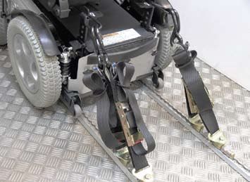
3.2      Label explanations
Labels and their descriptions

 Warning - Do Not Touch - HOT                                Lever position for the freewheel mechanism.

                                                             Attached to Joystick
 WARNING – Do Not Touch - Static may damage equipment        WARNING – Do not drive your wheelchair on a slope
                                                             with the backrest reclined and/or the seat lifted

                                                                                      MAx

                                                                                     75 kg
                                                                                    140  Kg

                                                             WARNING - For the Zippie Salsa / Salsa M the max.
 WARNING – Danger of finger entrapment                       load is 75 kg

               Location of 70Amp circuit breaker             Indicates battery charge point
    (not fitted to products after approximately June 2011)

 Lever position for the LEFT-HAND freewheel mechanism
 SALSA M (& SALSA from August 2010).                         Lever position for the RIGHT-HAND freewheel mechanism
                                                             SALSA M (& SALSA from August 2010).
 Tick = IN DRIVE, Cross = IN FREEWHEEL                       Tick = IN DRIVE, Cross = IN FREEWHEEL

8   ZIPPIE SALSA & SALSA M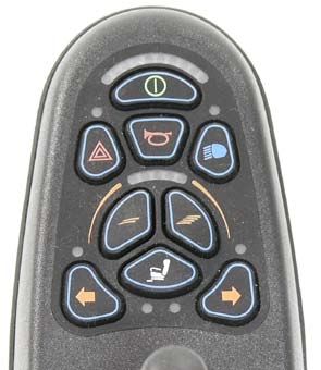
Labels and their descriptions

Battery Label – Warning Instructions and Circuit Diagram

Back Rest Recline                                          Elevate

                                                           The power Tilt and power Lift/Tilt modules are factory fitted
                                                           for optimum stability and for conformance to strict standard
Seat Tilt in Space                                         requirements. Changing the fitted position of the module can
                                                           reduce the stability of the product, therefore do not change this
                                                           setting.

                     Left footrest

                 Right footrest

                     Both footrests
                                                           WARNING: When the seat assembly is raised you
                                                           must always use the seat stay

 Do not engage Brake release whilst on a slope             Ensure drive is engaged before starting off.

                                                                                                                 ZIPPIE SALSA & SALSA   9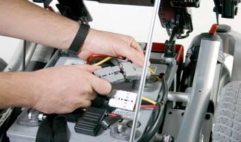
4.0 General safety warning and user tips                        4.4 Routine service
                                                                The recommended service interval is one year. (See
4.1 General warnings                                            service history table, section 14, Fig. 14.1).

           WARNING!                                             4.5 Brake release
•    Always ensure that your wheelchair is switched off                 DANGER!
     before attempting to transfer in or out.
•    Always ensure that you are able to operate all controls    •     The Brake release, (freewheel), is only to be used in
     from a comfortable position. Paying attention to your            an emergency power breakdown situation e.g. Where
     posture is essential to ensure your continued comfort            a large distance has to be covered to get the user
     and well being.                                                  home or into a safe environment.
•    Always make sure that you can be seen clearly,             •     Brake release can also be used if a complete and
     especially if you intend using your wheelchair in poor           catastrophic loss of power such as control system
     light.                                                           failure or battery failure has occurred.
•    This wheelchair has been built to match the needs of       •     Brake release should not be habitually used as
     a particular user. If used by another user then it may           a means of transporting the user as if in a manual
     need to be adjusted and reprogrammed.                            chair.
•    Never let anyone use your wheelchair without               •     When the power chair is functioning normally, the
     authorisation.                                                   brake release should only be used to park or store the
•    Be aware that the wheelchair may come to a sudden                unoccupied wheelchair.
     stop during operation. Sunrise Medical recommend           •     Do not operate the freewheel device whilst seated in
     that a lap strap be worn at all times.                           the wheelchair.
•    Do not operate the wheelchair if it is behaving            •     The freewheel device should only be operated by a
     abnormally or erratically.                                       person who has the strength and agility to be able
                                                                      to fully manoeuvre the wheelchair safely, during
4.2 Features and options                                              freewheel.
NOTE: Some of the options shown in this manual may
not be available in your country and may also restrict          Please remember that you have no braking facility when
the overall physical limits of the standard product (e.g.       the Brake release, (freewheel), levers are moved from the
max speed, user weight limit, etc.). Those limitations are      normal drive position to the freewheel position.
marked on the order form, in the technical manual and in        Fig. 4.3 and Fig. 4.4 .
this owner’s manual. For further information please consult
your Sunrise Medical authorised dealer.                                 DANGER!

4.3 Kerbs                                                       •     Always ensure an attendant is with you when bringing
                                                                      the chair into the freewheel mode.
        DANGER!                                                 •     The wheelchair must never be left with one or both
                                                                      levers in the freewheel position.
•    Never descend a kerb Forwards with a RWD chair or
     Backwards with a MWD chair. Please read carefully          For an enhanced description of this facility and its
     the section 4.30 on kerb climbing in this manual before    limitations to use, please see later section at 5.4.
     attempting to mount and dismount any kerbs in your
     wheelchair.
•    Do not attempt to climb or descend a series of steps. It       Fig. 4.3                    Fig. 4.4
     is unsafe to do so and could cause personal injury or
     damage the chair. The ZIPPIE SALSA & SALSA M has
     only been designed to climb a single step or kerb.
•    We recommend that users with upper trunk instability
     wear further customised restraint systems to keep the
     upright body position during descending or ascending
     ramps, curbs or obstacles.

10   ZIPPIE SALSA & SALSA M
4.6 EMC - Radio transmitting devices. 4.9 Batteries
Your wheelchair is supplied as standard from Sunrise
WARNING! Medical with maintenance-free batteries. These only
require regular charging. Before charging, please read
When operating two-way radio, walkie-talkies, C.B., amateur sections 10 and 12 in this manual.
radio, public mobile radio and other powerful transmitting
devices the wheelchair should be brought to a halt and WARNING!
turned off.
The operation of cordless, mobile telephones and cell Do not, under any circumstances, tamper with the
phones including hands-free devices is permitted but if batteries. If in any doubt contact your local Sunrise
abnormal operation of the wheelchair is encountered then Medical authorised dealer.
the chair must be brought immediately to a halt and turned
off. CAUTION!
NOTE: the electrical systems of the wheelchair may disturb
Before using your vehicle for the very first time, please
the performance of alarm systems in retail shops.
charge your batteries for a period of 24 hours.
4.7 Emergency braking WARNING!
There are three ways to stop your wheelchair:
1. Simplest and safest way to stop the wheelchair is to Avoid contact with acid on damaged sealed type batteries
release the joystick (see Hand Control section 7). This will or wet batteries. Battery acid can cause burns to the skin
bring the chair to a halt in a controlled manner. as well as damage to floors, furniture and your wheelchair.
If it comes into contact with the skin or clothing, wash
2. Pulling back the joystick will brake the chair abruptly with a immediately with soap and water. If it comes into contact
fast stop with the eye, immediately flood the eye with running cold
3. Switching the control system off whilst the chair is in water for at least 10 minutes and seek medical attention
motion will also bring the chair to a halt. immediately. Acid can be neutralised with baking soda
and water. Take care to keep batteries upright at all times,
WARNING! especially when transporting your wheelchair.
• Switching the control system off is only to be used in Battery and charger connector type ZIPPIE Salsa R:
an emergency situation as the stopping action is very 24V (2x12V) / 60 Ah/20h. Maintenance free batteries
abrupt. Dimensions: 197 x 165 x 197 mm.
• Sunrise Medical recommend the use of a lap strap at Battery and charger connector type ZIPPIE Salsa M:
all times. 24V (2x12V) / 51 Ah/20h. Maintenance free batteries
Dimensions: 228 x 139 x 235 mm.
4.8 Sharp turns
Connector: 3 pins “Neutrik” type
DANGER!
4.10 Tyres
Full speed turns should not be attempted. If you need to Your wheelchair tyres can wear depending on use. Check
turn sharply you must reduce your speed with the joystick or them regularly in accordance with the service instructions
speed setting. This is particularly important when travelling in this manual, especially the pressure of the tyres.
across or down a slope. Disregarding this advice could lead
to your wheelchair tipping over. DANGER!
Never inflate the tyres using a garage forecourt airline,
always use the pump provided.
ZIPPIE SALSA & SALSA 114.11 Weight limit 4.14 Wheelchair range
The range of your wheelchair can be affected by many
DANGER! factors such as user weight, terrain, ambient temperature,
use of powered options and battery condition.
• The user plus items carried should never exceed a
total weight of: 75 kg. NOTE: The stated range in the sales literature should be
• Never use this chair for weight training if the total weight seen as the theoretical maximum (ISO 7176; Part 4) and
(user plus additional weights) exceed a total weight of may not be attained by every user (also see section 10.11
75 kg. and section 13, in this manual).
• Exceeding the weight limit is likely to damage the seat, We recommend that every user initially limit their journey
frame or fasteners and may cause severe injury to you to half the stated range, until they have confidence in the
or others from chair failure actual range their wheelchair can attain.
• Exceeding the weight limit will void the warranty.
CAUTION!
4.12 Wheelchair motors
After prolonged use, the motors will produce heat, which is If your battery indicator is showing a low charge then do not
radiated through the motors’ outer casing. attempt a long journey unless you are confident in reaching
your destination and also returning to your home without
WARNING! the risk of being left stranded.
Do not touch the motors’ outer casing for at least 30 minutes
after using the wheelchair, to allow it to cool. 4.15 Road use
(Fig. 4.5). Please show the utmost consideration for the other traffic
on the road.
DANGER!
4.13 Hot surfaces
Not only the motors can get hot during the operation of the Remember that the last thing a car or lorry driver expects
chair, but also the upholstery material and armrests when to see is a wheelchair backing off the kerb into the road.
standing in the sun. If in any doubt, do not risk crossing the road until you are
certain that it is safe. Always cross the road as quickly as
Fig. 4.5 possible; there may be other traffic.
12 ZIPPIE SALSA & SALSA M4.16 Adverse conditions 4.18 Transfer to and from the chair
Please be aware that when driving your wheelchair in
adverse conditions, e.g. on wet grass, mud, ice, snow or WARNING!
other slippery surfaces, you may experience a reduction in
the grip and traction of your wheelchair. Sunrise Medical recommend that you consult your
healthcare professional for assistance in developing your
WARNING! personal front or side transfer technique to best suit your
needs and avoid any personal injury.
We recommend you take extra precautions in these
conditions, particularly on hills and slopes; your wheelchair WARNING!
could become unstable or skid causing possible injury.
Ensure controller is switched off during transfers to avoid
NOTE: Extreme variances in temperature may trigger the unintentional movement.
self protect mechanism in the control system. If this occurs
the control system will temporarily shut down to prevent 4.19 Lift and tilt modules
damage to the electronics or the chair.
WARNING!
4.17 Ramps Please be aware that the lift and tilt modules present a trap
hazard. Make sure that when operating the tilt and lift it is
WARNING! free from all clothing, hands, feet and other extremities to
prevent injury.
When using a ramp, please ensure that it is capable of
taking the combined weight of the power chair and yourself. WARNING!
If a ramp is being used to load a chair into a vehicle, please
ensure the ramp is properly secured to the vehicle. • Do not drive on ramps or slopes with the seat tilted,
Always approach the ramp head-on and exercise caution. reclined or raised. Before attempting to climb or decline
a slope, return to an upright position
CAUTION! • The power Tilt and power Lift/Tilt modules are factory
fitted for optimum stability and for conformance to strict
Please ensure your ramp is suitable for the product you are standard requirements. Changing the fitted position
transporting. of the module can reduce the stability of the product,
therefore do not change this setting.
WARNING!
Risk of trapping fingers:
The optional protection guard if fitted, secures the
moving parts within the lift / tilt mechanism. Although
better protected, always be careful not to get your fingers
trapped in the mechanism. It is recommended to re-install
the protection guard as described in the Salsa technical
manual after any service or repairs to the lift / tilt module.
Please consult your approved Sunrise Medical Dealer.
ZIPPIE SALSA & SALSA 134.20 Anti-tip tubes 4.21.2 Gradients: descents
WARNING! WARNING!
• Make sure that anti-tips are not damaged or worn On descents, it is important not to let the wheelchair
before using your chair. accelerate beyond its normal level of ground speed. In fact,
• Attendants must be aware of the location of the anti- it is safer to proceed slowly down steep descents (below
tips to prevent feet being trapped underneath causing the speed of 5kph) and stop, if any anxiety arises regarding
injury. directional control. If the chair picks up speed, centre the
• Attendants - Do not stand on the anti tips, this could control to slow it or to stop all forward movement then
cause the wheelchair to become unstable. restart slowly and do not allow the speed to increase.
4.21 Use on a slope NOTE: The solid state controller has the benefit of a logic
Your wheelchair has been designed and tested to allow its system that will help compensate when driving along a
use on slopes or gradients of up to 8° (14%). However, you camber or up a hill. This is an added safety feature on
have the option of adjusting your seating position with either your wheelchair. In addition of course, you may control the
a lift, tilt or recline or a combination of these options. wheelchair speed by using the speed control.
WARNING!
4.22 Using a vehicle mounted passenger lift
In certain circumstances your wheelchair could become Wheelchair lifts are used in vans, buses and buildings to
unstable. Before attempting to climb or descend a slope help you move from one level to another.
or a kerb, caution should be taken when using weight shift
options (e.g. powered tilt or recline), of the seat and/or your DANGER!
body for a counter balance weight. To improve stability
lean forward when driving uphill, with the seat and back in • Ensure that the user and all carers fully understand the
an upright position. Alternatively sit in an upright position lift manufacturer’s instructions for using the passenger
when travelling in a forward, downhill direction or tilt and/or lift.
recline the seat backwards. • Never exceed the lift manufacturer’s recommended
safe working load and load distribution guidance.
WARNING! • Always turn off all power when you are on the lift. If you
fail to do so, you may touch the joystick by accident
We strongly recommend that you return the seat and back and cause your chair to drive off the platform. Be
to an upright lowered position before attempting to climb aware that a rollstop at the end of the platform may not
or descend a slope. Failure to do this may cause the prevent this.
wheelchair to become unstable. • Always position the user securely in the chair to help
avoid falls while on the lift.
WARNING! • Always ensure the chair is in drive mode when using
passenger lift (wheels locked not in freewheel mode).
If you are in any doubt about the capabilities of your
wheelchair on a slope then do not attempt to drive up or
down the slope/kerb; try to find an alternative route.
4.21.1 Gradients: ascents
WARNING!
When going uphill, keep the chair moving. Steer by moving
the joystick from side to side. If you have stopped on a
hill, you should start slowly. If necessary lean forward to
prevent the tendency for the front wheels to lift.
14 ZIPPIE SALSA & SALSA M4.23 Creep mode Furthermore different body proportions of a wheelchair
user affect stability for example:
WARNING! • Lower limb wasting or amputation, Obesity
• Increased upper torso mass, Upper torso height
Please ensure your backrest recline angle relative to floor
level, (which is a combination of the back recline itself WARNING!
and the tilt angle), does not exceed 12° to drive the chair
safely. The power Tilt and power Lift/Tilt modules are factory fitted
for optimum stability and for conformance to strict standard
NOTE: f the tilt angle exceeds 9° the chair will the chair will requirements. Changing the fitted position of the module
automatically convert into “creep mode” which will allow can reduce the stability of the product, therefore do not
you a maximum of 10% of the speed programmed in the change this setting.
profile.
4.25 Wheels
WARNING!
WARNING!
If you have a manual recline backrest on your wheelchair,
please be aware that there will be no feedback system • Always use the pump that is supplied with the chair.
to the controller that tells it that the seat is in a reclined • Never use a forecourt pump
position. If you recline your backrest and attempt to drive, it • Inspect all tyres regularly for signs of wear.
will not go into ‘creep mode’, it will instead drive at normal • Do not drive over anything that could cause punctures
speed. in the tyres.
This is especially dangerous when attempting to drive up • Ensure that there are no objects in your path that could
a slope. possibly become lodged in your chair mechanism or
in the spokes of the rear wheels. This could cause the
WARNING! chair to come to a sudden stop.
• Riding over drains or grids could cause the wheelchair
On any Reclining Backrest, the Lower fixing positions of castors or wheels to become lodged, causing the chair
either the Powered Actuator or Manual Gas Strut, MUST to come to a sudden stop.
correspond to the Seat Depth being used. • Always maintain the correct pressure for the tyre.
Following Seat depth Adjustment you MUST ensure the These are listed in section 12 of this manual.
Lower actuator/Gas strut position matches the seat depth
set, i.e. use the 17”, (430 mm) Hole in the lower bracket
for a seat depth of 17”, (430 mm). WARNING!
Please see section 5.2.1 for details.
Pneumatic Tyres with OKO fluid.
4.24 Stability of your wheelchair The OKO fluid is only meant as a temporary repair to the
Please follow the user instructions in this manual regarding tyre. It must be replaced or repaired as soon as possible.
the use of seat lift and tilt modules and the use of your The OKO fluid is classified as non hazardous but may
chair on a slope. cause irritation to the skin with prolonged contact.
WARNING!
First Aid measures for OKO fluid
Skin - Wash skin with plenty of water
Other variables can affect your chair stability, including:
Eyes - Immediately flood the eye with plenty of water for
• Movement of the user
at least 5 minutes holding the eye open.
• Effects of the addition of accessories or other
Ingestion - Drink lots of water - Seek medical attention
equipment
immediately.
• Inappropriate adjustments or modifications to the
wheelchair
In some cases these issues are further compounded by
the effects of the local environment such as:
• Hills, Slopes, Ramps, Sloping pavements, Dropped
kerbs.
ZIPPIE SALSA & SALSA 154.26 Rear view mirror 4.29.1 Seat stay
A seat stay is provided on your powerchair to provide
WARNING! access for service and maintenance. (see section 10 for
additional information)
To avoid injury to people around you please be aware that
the mirror protrudes outside the space envelope of the chair WARNING!
and could cause injury to someone when driving past.
The mirror must be used on the 10KPH model on UK Do not move the wheelchair with the seat stay in place and
roads. make sure you are on flat stable ground. Make sure that
Always make sure that when using the mirror that it is clean the plastic cap is securely fitted over the seat height tube.
and unbroken so that it does not impair your visibility.
4.30 Using a kerb climber
4.27 Crutch holder
WARNING!
WARNING!
Ensure there are no people or other obstacles in your path
• Make sure that the crutch is securely fastened to the when mounting a kerb or step.
crutch holder.
• Make sure that the crutch is not interfering with the 4.30.1 Mounting a kerb or step
mechanisms of the chair.
• Make sure that the crutch does not protrude from the WARNING!
chair.
• Do not attempt to remove the crutch whilst the chair is in Always approach a kerb at 90°
motion.
• Always come to a complete stop and turn off the power Approach the kerb (step) head on driving forwards slowly
to the controls before attempting to remove the crutch. and steadily and always at a 90° angle, (Fig. 4.7).
This will avoid accidentally operating the chair.
4.28 Lights and indicators
WARNING!
Ensure that the lights and indicators are functioning
correctly and lenses are clean before going outdoors at
night. Light assemblies can become very hot. Care must
be taken if removing them for repair.
4.29 Swing away tray Fig. 4.7
WARNING!
ZIPPIE Salsa R (RWD)
• The maximum weight allowed for the tray is 2.5kg. As the kerb climber or castor makes contact with the kerb
• Do not overload the tray; this could cause the tray to (step), the wheelchair should be moving slowly. Small kerbs
break or could cause the chair to become unstable. can be climbed from a standstill (Fig. 4.8 - 4.9).
• Do not leave lit cigarettes or other heat sources on the
tray as this could cause the tray to deform and mark.
• Ensure that all extremities and clothing are free when
positioning the tray for use.
Fig. 4.8 Fig. 4.9
16 ZIPPIE SALSA & SALSA MZIPPIE Salsa M (MWD) WARNINGS!
Approach the kerb in a 90° angle and stop the chair as
soon as the castor wheels touch the kerb. 1. Please show the utmost consideration for the other
Apply sufficient power to the motors to lift the front of the traffic on the road. Remember that the last thing a car or
chair up onto the kerb (step) and then apply slightly more lorry driver expects to see is a wheelchair backing off the
power and speed so that the drive wheels climb the kerb kerb into the road. If in any doubt, do not risk crossing the
(step) smoothly and without hesitation and the rear castor road until you are certain that it is safe.
wheels come up as well. As far as possible, keep the
joystick in the straight forward position (Fig. 4.10 - 4.11). 2. Always cross the road as quickly as possible; there may
be other traffic.
Fig. 4.10 Fig. 4.11
3. Do not attempt to go up or down more than a 10 cm (4”)
high kerb (Salsa only with kerb climber fitted).
4. Do not attempt to use the kerb climber on a series of
steps.
5. Do not attempt kerbs if on steep slopes or cambers.
6. Do not attempt any kerbs in the vicinity of drain covers,
uneven or gritty road surfaces.
Note: In accordance to the ground clearance, the maximum
obstacle height possible to climb is 5 cm (10 cm with kerb 7. You should not attempt to dismount a kerb any higher
climber) for Salsa R and 7.5 cm for Salsa M. than 5 cm (2”) in the forwards direction.
WARNING! 8. You should always drive towards a kerb in a perpendicular
manner (i.e. at a 90° angle) when you want to go up or
The approach speed and process can vary depending on down a kerb.
your wheelchair performance and castor wheel choice.
9. Prior to climbing ensure your legrests will clear the kerb.
4.30.3 Kerb climber fitting and removal procedure 10. Take care of the anti-tips which might interfere with the
(RWD base only) kerb or the ground when mounting or dismounting a kerb.
• Locate the kerb climber bar into the left hand location WARNING!
bracket and push it into the right hand receiver bracket
(Fig. 4.12 and Fig. 4.13). This wheelchair is designed to be repaired and assembled
by a Sunrise Medical authorised dealer and not the end
• Hold the kerb climber with your left hand in the receiver user. The end user has to disassemble and assemble the
bracket. chair only for transportation (see section 5.2).
• Align the holes of the receiver bracket and the kerb
climber tube and plug in the locking pin from the top. 4.31 Lap belt
The lap belt kit. (Fig. 4.14).
• Reverse the procedure to remove the kerb climber.
Fastening the lap strap:
Insert the 3 prong male buckle into the female buckle until
a click is heard (Fig. 4.15)
Fig. 4.12 Fig. 4.13
To fit the lap strap.
Place the strap loosely across the seat with the buckle
closed.. (Fig. 4.16)
Pass the other ends of the strap through the gap between
the backrest posts and the backrest upholstery as shown.
(Fig. 4.17)
Ensure that the adjusters & buckles can be accessed & the
strap is not twisted. Fit the eyelet over the rearmost bolt.
Fit the plain washer, sprung washer & nut. Tighten with a
13.0mm spanner. Repeat for the other side. (Fig. 4.18)
Ensure that the lap strap is tight enough to provide
comfortable support. A simple measure is to keep a hands
thickness between the body and lap strap. For safety,
check the tension on the lap strap at least once day. (Fig.
4.19)
ZIPPIE SALSA & SALSA 17Generally, the lap belt should be fixed so that the straps DANGER!
sit at an angle of approximately 45° (Fig. 4.20). and when
correctly adjusted should not allow the user to slip down in • In the event of the wheelchair moving in an unexpected
the seat. way RELEASE THE JOYSTICK. This action will stop
the wheelchair under any circumstances
• Do not operate the control system if the wheelchair
behaves erratically or shows abnormal signs of heating,
sparks or smoke. Turn the control system off at once
Fig. 4.14 Fig. 4.15 • and consult your Sunrise approved dealer.
R-net Control Please refer to your R-net Owner’s
Manual for details.
Battery Gauge
Fig. 4.16 Fig. 4.17
On/off button
Horn
Speed Indicator
Speed Buttons
Fig. 4.18 Fig. 4.19
Joystick
Fig. 4.20
Fig. 4.21
4.4 Third party seating systems
WARNING!
Should you wish to fit a third party seating system, please
make sure that the seat surface of the seating system
overhangs the metal base plate by maximum 1 cm at the
front, in order to guarantee the dynamic and static stability
4.32 VR2 Controller (Fig. 4.21)
of the wheelchair.
WARNING!
• Avoid knocking your control system and especially the
joystick.
• Be careful not to strike obstacles with the control
system or joystick when you drive.
• Never drop the control system.
• When transporting your wheelchair, make sure that the
control system is well protected.
• Avoid damage to cables.
• To improve the reliability of the control system keep
exposure to extreme conditions to a minimum.
• Do not expose your control system or its components
to damp for prolonged periods.
• If your control system becomes contaminated with food
or drink clean it off as soon as possible.
18 ZIPPIE SALSA & SALSA M5.0 Preparing your wheelchair for use
WARNING!
5.1 Handling the wheelchair
Note - To dismantle the chair for transport or storage no The Lower position of the Powered Actuator Strut MUST
tools are required. correspond to the Seat depth being used, (Fig.5.8).
List of components when dismantled (components Following Seat depth Adjustment you MUST ensure the Lower
below are related to the maximum detachable parts and actuator strut position matches the seat depth set, i.e. use the
dependent on the type of seating system chosen): 36cm Hole in the lower bracket for a seat depth of 36cm.
1 pair of armrests
1 pair of footrests
Fig. 5.8
1 backrest
1 drive unit with seat frame.
5.2 Preparation for transportation or storage
First remove the swing-away legrests. Leave the armrests
in the fold down position. (Fig. 5.1). Disconnect the Hand
Control, if necessary (Fig. 5.2). To remove the control pod
you have to access the motor controller through the plastic
cover between the castor wheels and remove the square
remote control connector.
Place the control pod & arm in a safe place until required.
To reconnect the hand control just use the process in
reverse. Release and lift off the standard backrest at the
frame (Fig. 5.3 - 5.4). Now you can store the chassis part.
By releasing the freewheel mechanism on the left and right
side of the chassis you can move the drive unit as close as
possible to the place you want to store it.
You can also drive the base with the joystick up or down a
ramp into and out of a car for transportation.
WARNINGS!
• Make sure, when the chair is stored or left in the car or
anywhere else, the controller is switched off and the
freewheel mechanisms are engaged.
• If there is a need to lift the drive unit the big side frame
tubes should be used. Caution should be taken if the
chair is in freewheel.
Fig. 5.1 Fig. 5.2
Fig. 5.3 Fig. 5.4
ZIPPIE SALSA & SALSA 195.3 Re-Assembling ZIPPIE SALSA M & SALSA (Fig. 5.12 and 5.13)
Replace the backrest into the receivers and tighten the By rotating the red lever outwards on both sides of the
lever screws carefully. If required reconnect the remote motor the brakes are released from the motors.
controller. Attach the hangers. Make sure your freewheel Please ensure the controller is switched off before you
mechanisms are engaged. Now you are ready to drive the engage the release levers – Failure to do so will increase
chair. the force needed to push the chair.
WARNING!
Never lift the wheelchair by the armrests or the leg rests,
since they are detachable and harm could be done to the
user or to the wheelchair.
Fig. 5.12 Fig. 5.13
DANGER!
• The chair’s automatic braking system will not work
Fig. 5.9
unless the brake release levers are in the “drive” or
down position.
• Motor surfaces can be hot after use. Be careful not
5.4 Brake release to touch the motor casing when disengaging the
freewheel.
DANGER! • Never attempt to disengage the brake release
mechanism whilst sitting on a slope.
• The Brake release, or the Low push force drive release • Always ensure the Brake release levers are returned
featured in section 5.4.1, (LPFDR), is only to be used in to the down / drive position.
an emergency power breakdown situation e.g. Where a
large distance has to be covered to get the user home 5.4.1 Low push force drive release, (LPFDR)
or into a safe environment.
• Brake release or LPFDR, can also be used if a complete NOTE: In case your powerchair is fitted with the low push
and catastrophic loss of power such as control system force drive release, the following instruction applies:
failure or battery failure has occurred.
• Brake release or LPFDR, should not be habitually used When switched off the powerchair remains immobile due to
as a means of transporting the user as if in a manual the positive locking action of the automatic electromagnetic
chair. brakes built onto the motors.
• When the power chair is functioning normally, the brake If you need to move the powerchair without the use of
release or LPFDR, should only be used to park or store battery power then operate the brake release levers
the unoccupied wheelchair. (Fig. 4.1 - 4.4) as described in section 4, or Fig. 5.10 - 5.13,
• Never push the occupied power chair up or down as described in section 5.4).
a slope with either the Brake release or LPFDR in However if the force needed to push the powerchair to
operation. too high for you to manage then the low push force drive
release may be used (Fig. 5.14 - 5.15).
Fig. 5.14 Fig. 5.15
20 ZIPPIE SALSA & SALSA MDANGER! 5.5 Drive wheel suspension
The ZIPPIE SALSA M/R has an effective and adjustable
The LPFDR should only be used with a user in the power- drive wheel suspension system as a standard feature. To
chair in Emergency situations as the automatic brakes will match your requirements on drive comfort, the tension of
become inoperable.
the springs at the damper can be adjusted.
DANGER! Turning the aluminium ring away from the spring will soften
your ride, adjusting the aluminium ring in a position towards
The automatic brakes become inoperative when the Brake the spring will harden it. This option is to be used to match
release, or LPFDR is disengaged allowing the power chair the different user weights to the suspension system, (Fig.
to run free if left on an incline. 5.16 and 5.17). We recommend the suspension adjustments
are done equally on the left and right side of the chair.
DANGER!
There is an independent device in each wheel that has to
be disengaged separately.
• DO NOT disengage the LPFDR if the powerchair is
located on a slope.
• Disengaging one side may result in the chair turning on
the slope and disengaging both may result in the chair
rolling down the slope. Fig. 5.16 Fig. 5.17
• DO NOT disengage both the Brake releases and
LPFDR devices at the same time.
• DO NOT switch on and operate the powerchair control 5.6 Control joystick unit position
system whilst the LPFDR is disengaged.
• Always re-engage the drive mechanism on the drive WARNING!
wheels when the chair is not being pushed.
• Make sure that the control system is mounted securely
To disengage the LPFDR pull out and push over the and that the joystick position is correct.
operating cam lever and to engage the LPFDR, pull out • The hand or limb you use to operate the joystick should
and push over the operating cam lever (Fig. 5.15). be supported, for example by the arm pad.
• Do not use the joystick as the sole support for your
DANGER! hand or limb - wheelchair movements and bumps could
upset your control.
The drive and brakes will NOT become operable until the
internal parts of the LPFDR are re-aligned. The remote is mounted on a sliding mechanism which
enables the control to be moved forwards and backwards.
To re-align the LPFDR, push the powerchair forwards or When the most comfortable position has been selected,
backward in a straight line until the parts automatically secure the slider by tightening the locking screw.
re-engage and the brakes comes on.
WARNING!
DANGER! Ensure the locking screw is fully tightened prior to use,
especially when transporting your wheelchair.
The LH and RH side may not re-engage at the same time
so make sure that both are re-engaged before turning the 5.7 Getting ready to drive
powerchair on.
• Operate the On/Off switch. The battery gauge will blink
then remain on after a second
• Check that the maximum speed is set to a level which
suits you.
• Push the joystick to control the speed and direction of
the wheelchair
ZIPPIE SALSA & SALSA 215.8 Armrests
5.8.1 Armrests-removing and replacing
The armrests on both sides of the wheelchair can be flipped
up to allow side transfer, (Fig. 5.18).
For side transfer flip the armrest all the way up until it goes
into its mechanical stop. This frees your space for side
transfer.
To bring the armrests back into their position flip it all the
way down until it sits on its mechanical stop. Guide it in its
downward movement and do not let it fall on its own.
Fig. 5.19
Fig. 5.18
5.8.2 Armrest Height Adjustment
The following section outlines armrest height adjustment.
In the case of either fine or gross adjustment, it is a
two-part process:
PART I: Adjust the armrest height through rotation
PART 2: Adjust arm pad angle.
1. Basic fine adjustment. Fig. 5.20
PART 1 (Fig. 5.19 and 5.20)
Up to one inch of armrest height adjustment can be
achieved using the 5mm fine height adjustment screw to
fine tune the armrest’s height.
1. Loosen the 6mm rotation bolts on both armrests (A).
2. Turn the adjustment screws (B) counter-clockwise to
raise the armrest or clockwise to lower.
3. Retighten both rotation bolts (A).
Use 20 N/m or 177 in/lb of torque.
PART 2 (Fig. 5.21 and 5.22)
1. Loosen the 4mm arm pad angle pivot bolts (A) on both
armrests. Remove the 4mm angle index bolts (B) on Fig. 5.21
both armrests.
2. Tilt both arm pads down, (or up in the case of a lowered
armrest), until the arm pads are in the preferred angle.
Check to see if the height is correct.
3. Retighten both arm pad angle pivot bolts (A). Replace
both armpad angle index bolts (B).
Use 10 N/m or 88.5 in/lb of torque for both sets of bolts.
Fig. 5.22
22 ZIPPIE SALSA & SALSA M2. Basic coarse adjustment.
PART 1
1. To achieve more than one inch of adjustment, remove
the 6mm armrest rotation bolts on both sides of the
seat (Fig. 5.23).
2. Remove both armrest assemblies. (Fig. 5.24)
3. Remove both sets of 4 mm armrest adjustment ring
bolts (Fig. 5.25).
4. Rotate the armrest height adjustment rings (Fig.
5.26) to match the desired height designated in the
Configuration Chart (Fig. 5.35) on page 25.
Fig. 5.25
5. Replace both sets of armrest adjustment ring bolts
according to the Configuration Chart. (Fig. 5.27)
6. Use 10 N/m or 88.5 in/lb of torque.
7. Replace both armrest assemblies. (Fig. 5.28)
8. Replace the armrest pivot bolts on both sides of the
seat, but do not tighten completely. (Fig. 5.29)
Fig. 5.26
Fig. 5.27
Fig. 5.23
Fig. 5.28
Fig. 5.24
Fig. 5.29
ZIPPIE SALSA & SALSA 23PART 2
1. Loosen the 4mm arm pad angle pivot bolts (A) on both
armrests. Remove the 4mm angle index bolts (B) on
both armrests (Fig. 5.30).
2. Use the 5mm fine height adjustment screw (B) to
finish fine tuning the height. Turn counter-clockwise to
increase height or clockwise to lower (Fig. 5.31).
3. Tilt both arm pads down, (or up in the case of a lowered
armrest), until the arm pads are in the preferred angle.
Check to see if the height is correct (Fig. 5.32).
4. Refer to 2 for fine adjustment.
5. Retighten both armrest pivot bolts (Fig. 5.33).
6. Use 20 N/m or 177 in/lb of torque.
7. Retighten both arm pad angle pivot bolts (A). Replace
both arm pad angle index bolts “B” (Fig. 5.34). Fig. 5.31
8. Use 10 N/m or 88.5 in/lb of torque for both sets of
bolts.
Fig. 5.32
Fig. 5.30
Fig. 5.33
Fig. 5.34
24 ZIPPIE SALSA & SALSA MA B C
Backrest angle Ring position Armrest
170 mm min.
A 175 mm max.
170 mm min.
-4° B 255 mm max.
245 mm min.
C 275 mm max.
170 mm min.
A 185 mm max.
175 mm min.
0° B 265 mm max.
255 mm min.
C 275 mm max.
170 mm min.
A 195 mm max.
190 mm min.
4° B 275 mm max.
260 mm min.
C 275 mm max.
170 mm min.
A 205 mm max.
200 mm min.
8° B 275 mm max.
N.A min.
C max.
170 mm min.
A 215 mm max.
210 mm min.
12° B 275 mm max.
N.A min.
C max.
170 mm min.
A 225 mm max.
215 mm min.
16° B 275 mm max.
N.A min.
C max.
ZIPPIE SALSA & SALSA 255.8.3 Arm pad Position Adjustment (Fig. 45 - 48)
1. Fine arm pad position adjustments (one to two
inches) are possible by loosening the 4mm arm pad
adjustment bolts (E) and sliding the arm pad forward or
backward as required (Fig. 5.36, 5.37). Access to the
rear adjustment bolt may require pivoting the arm pad
2. Retighten both adjustment bolts (E). Use 10 N/m or
88.5 in/lb of torque (Fig. 5.38).
NOTE: If more than one to two inches of adjustment is
required, refer to chart below (Fig. 5.39).
3. For larger adjustments, remove both sets of arm pad
adjustment bolts. Slide both arm pads to the next set
of attachment holes (refer to the chart). Retighten both Fig. 5.36
sets of armpad adjustment bolts (Fig. 5.36 - 5.39). Use
10 N/m or 88.5 in/lb of torque.
Fig. 5.39
Fig. 5.37
ARM PAD DEPTH
ARMREST
HEIGHT
Fig. 5.38
Arm-pad depth = min. 235 mm to max. 300 mm
(back tube to front edge of arm-pad)
26 ZIPPIE SALSA & SALSA M5.9 Legrests Fig. 5.42
WARNING!
Be aware of your environment to make sure you do not
injure your legs when legrests are extended.
WARNING!
Always ensure that the legrests or footplates do not come
into contact with the castors before driving the wheelchair.
WARNING!
Legrests are not to be used for lifting or carrying the
wheelchair with an occupant.
SCREWS
5.9.1 Fitting legrest
Offer the legrest assembly at right angles to the frame
(Fig. 5.40); locate the stem into the leg rest and swing the 5.9.4 Hanger depth adjustment (Fig. 5.43 - 5.45)
assembly forward to lock in position. To swing away the
footrest, depress the retaining catch and turn the footrest 1. Remove both sets of 5mm hanger depth adjustment bolts
out. This can now be lifted out if required, (Fig. 5.41). (Fig. 5.43).
2. Slide both hanger receivers to the desired location (Fig. 5.44
5.9.2 Footplates
inset (B).
The footplates may be flipped up to aid entry and exit from 3. Replace both sets of depth adjustment bolts (Fig. 5.45).
the chair. 4. Use 20 N/m or 177 in/lb of torque.
Fig. 5.40 Fig. 5.41
WARNING! Fig. 5.43 Fig. 5.44
Do not use the footplates to stand on as the full weight of
your body may cause the chair to tip forwards. This could
result in injury and could damage the footrest.
5.9.3 Adjusting the footrest length
To adjust the footrest length remove the screw assembly on
the footrest hinge as shown in (Fig. 5.42) adjust the length
to suit. Ensure the bolts are firmly located and tightened
prior to use.
Fig. 5.45
ZIPPIE SALSA & SALSA 275.9.5 Manual Articulating / Elevating Legrest (ALR/ VR2 Control:
ELR) The actuator buttons can operate any factory approved
actuator. Operation is dependent on what options are fitted
To elevate: to your wheelchair. To operate the back recline, seat tilt or
Pull the legrest upwards and stop at the desired height. seat lift.
The legrest will automatically lock in the chosen position. • Push one of the actuator buttons that has the seat icon
on it to select actuator mode
To lower: • Operate the joystick left or right to select the actuator
Push the release lever slowly forward. The legrest will lower required (actuator 1 or actuator 2). Selection is indicated
the angle. As soon as you release the lever, the legrest will via the lighting of the red LED adjacent to the desired
be locked in the current position (Fig. 5.46). actuator button.
• Operate the joystick in the forward or rearward direction
WARNING! to move the back recline, seat lift or tilt up or down.
• Release the Joystick when the desired angle is
Keep hands clear of the adjustment mechanism between reached.
the frame and the movable parts of the legrest while • To return to drive mode, press the actuator button
elevating or lowering the legrest. again. (Fig. 5.48)
As soon as any of the powered options reaches their
Fig. 5.46
maximum or minimum positions, let go of the joystick. Do
not hold the joystick in its operating position as this could
damage the actuators.
LEVER
Fig. 5.48
R-net Control
Please refer to your R-net Owner’s Manual for
details.
28 ZIPPIE SALSA & SALSA MQuickie Direct Actuator Control Box: 6.0 Seating
The direct actuator switches can operate any factory
approved actuator. Operation is dependent on what options 6.1.1 Solid seat.
are fitted to your wheelchair. To operate the legrests, seat The areas defined by labels on the seatplate can be used
tilt, seat lift or back rest recline. to help fit a third party seating system.
In the base plate, drill holes with a minimum gap of 20
• Push the toggle switch for the relevant actuator forward mm should be positioned in the small area 1 (Fig. 6.01) or
until you reach the required angle/height. in the large area 4 (Fig. 6.02) (max. Ø 7 mm). The areas
• Release the toggle switch and the actuator will stop. in which drill holes may be made are defined in Fig. 6.0 -
6.02.
When the actuator reaches its maximum/minimum position
do not hold the toggle switch in its operating position as
this could damage the actuator. (Fig. 5.49)
R-net Control
Please refer to your R-net Owner’s Manual for
details.
Fig. 6.0
Fig. 6.02 Fig. 6.01
110
1 DRILLING
4 DRILLINGS Max. Ø = 7m
130
Max. Ø = 7m
Min. Hole
Distance 20mm
Fig. 5.49
ZIPPIE SALSA & SALSA 29Fig. 6.2
6.2 Seat cushions
Seat cushions supplied by Sunrise Medical will have
Velcro® strips that correspond to patches on the seat. You
must ensure these are aligned prior to using the wheelchair.
Other cushions used should also have Velcro® strips in a
similar position to ensure the cushion does not slip off the
seat. The seat cushions, supplied by Sunrise Medical all
have removable covers.
6.3 Removable seat covers
The seat covers are all fully removable using zips or
Velcro® Once brackets are removed seat covers can be
removed. The zip for the backrest is located on the under
side of the cushion.
6.4 Standard backrest upholstery Fig. 6.3
Salsa is supplied with optima backrest upholstery, which
can be adjusted in tension to the individual’s requirements.
Tension adjustable back:
To change the shape and/or tension of the ‘Optima’ backrest,
remove the padded cover from the rear of the backrest and
expose the tension straps. Loosen or tighten the straps to suit.
(The most comfortable and supportive position is achieved with
the wheelchair user seated in the chair). Ensure the straps are
securely fastened and replace the padded cover prior to use.
6.5 JAY backrests
The standard backrest assembly will allow the fitting of a
JAY backrest, which is available as an optional extra.
6.6 Seat height adjustment
WARNING!
Make sure the top frame does not trap your fingers. Get
someone to hold the seat steady during adjustment.
Fig. 6.1
To change the seat height:
Salsa Rear Wheel Drive only:
• Remove the two bolts from the front seat posts, using
a 5mm allen key.
• Access the bolts by removing the front cover.
• Take the safety clips off the flat rear posts, pull the ring
pins out and loosen the two clamping bolts.
• Lift/lower the seat height by choosing the required hole
position on the rear seat posts.
• Replace the pins, clips and bolts. Tighten the bolts.
• Choose the matching set of holes for the front seat
posts. Replace and tighten the bolts (Fig. 6.4 - 6.5).
30 ZIPPIE SALSA & SALSA MYou can also read