The Good Practice Guide for the Installation of Replacement Windows and Doors
←
→
Page content transcription
If your browser does not render page correctly, please read the page content below

Cl/SfB
                                      Ro

                        Summer 2011        Issue 3

The Good Practice Guide
  for the Installation of
       Replacement
  Windows and Doors
Contents

    Introduction and Scope                              5

    Section 1 – Principles                              6
        General Requirements                            6
        Strength and Performance                        6
        Security Considerations                         8
        Safety Considerations                           9
        Planning Considerations                         10

    Section 2 - Surveying                               11
        General                                         11
        Building Regulations                            11
        Suitability of Aperture                         11
        Services in the Aperture                        12
        Design for Weather Performance                  12
        Lintels                                         12
        Brickwork Removal                               12
        Bow, Oriel and Dormer Windows                   13
        Bay Windows                                     13
        Roof Windows                                    13
        Coupled/Combined Frames                         14
        Opening Type and Direction                      14
        Doorsets                                        14
        Frame Drainage                                  15
        Decorative Glazing                              15
        Measurement                                     15
        In-check Reveal                                 16
        Manufacturing Sizes                             16
        Asbestos                                        17
        Surveyor’s Check List                           18
                  Window and Door Good Practice Guide
2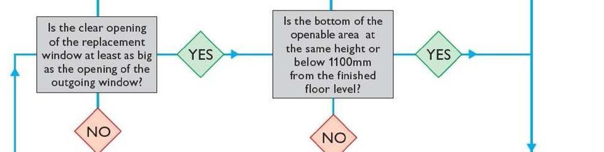
Contents

Section 3 - Installation                     19
     General                                 19
     Window Removal Techniques               19
     •    Timber Framed Windows and Doors    20
     •    Box Sash Windows                   20
     •   Metal Framed Windows                20
     •    PVC-U Framed Windows and Doors     21
     •   Sub-Sills                           21
     Window and Door Fixing                  21
     •   Fixings                             22
     •   Fixing Distances                    23
         •     PVC-U Windows and Doors       23
         •     Timber Windows and Doors      24
         •     Aluminium Windows and Doors   25
         •     Steel Windows                 25
     Roof Windows                            25
     Bay Poles                               26
     Installation Packers                    27
     Finishings                              27
     Frame Position                          27
     Open Cavities                           27
     Box Sash Windows                        28
     Glazing                                 28
     Scratched Glass                         29
     Finishing Off and Making Good           29
     Sealing                                 29
     Final Inspection                        30
     Final Inspection Check List             31

     Window and Door Good Practice Guide
                                                  3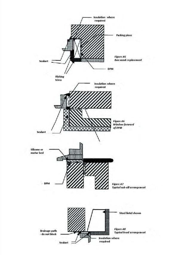
Contents
    Section 4 - Maintenance                                     32
        Glass                                                   32
        PVC-U Frames                                            32
        Aluminium Frames                                        32
        Timber Frames                                           32
        Steel Frames                                            33
        Roof windows                                            33
        Sealants                                                33
        Gaskets and Seals                                       33
        Hardware and Fittings                                   33
        Annex A                                                 35

    Section 5 - Building Regulations                            37
        AD A - Structure                                        38
        AD B - Fire Safety                                      41
        AD C - Resistance to Contaminants and Moisture          46
        AD F - Ventilation                                      49
        AD J - Combustion Appliances and Fuel Storage Systems   52
        AD K - Protection from Falling, Collision and Impact    55
        AD L - Conservation of Fuel and Power                   58
        AD M - Access To and Use of Buildings                   60
        AD N - Safety Against Impact                            62

    Section 6 – Bibliography and Descriptions                   65

                   Window and Door Good Practice Guide
4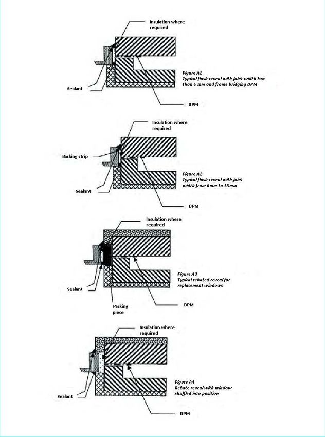
Introduction / Scope

This good practice guide has been developed by the GGF Window and Door Group -
Technical Committee. It is intended that this guide will assist those involved with the Sur-
vey, Installation and Use of Replacement Windows and Doors for Dwellings within
England and Wales. This guide will also be of benefit to those responsible for ensuring
that the fenestration complies with the Building Regulations.
This updated edition includes guidance on the safe removal of asbestos products, the re-
moval and replacement of bay windows and considerations of sealants.

             Window and Door Good Practice Guide
                                                                                           5
Section 1:
                                        Principles

General Requirements
The following matters need to be considered;
      • The need to provide a weather proof solution
      • The need to provide natural light and ventilation;
      • Design for safety in use;
      • Means of escape in case of fire;
      • Security against unauthorised entry;
      • Design for safety when cleaning;
      • Maintenance;
Note: The type of occupancy, and the age range of both occupants and visitors to the
building should also be considered. BS 8213-1:2004 advises that a risk assessment be
conducted by the designer (in the case of domestic replacement windows this is the
person or organisation taking the order from the client), taking account of the relative
priority needs established in each situation. If a significant change of use of the building
occurs, the risks should be reassessed.

Strength and Performance
The performance characteristics of external windows and doors are covered by European
Standard EN 14351. The Standard identifies performance characteristics that are
applicable to windows and doors and it identifies the test methods that should be used to
establish these characteristics. However, it does not actually specify the level of
performance that is required for the characteristics, because this varies according to the
climate or local building regulations.
This has been adopted as a British Standard, BS EN 14351. This standard will be
covered by the Construction Products Regulation regarding CE marking of products.

                        Window and Door Good Practice Guide
  6
Section 1:
                                        Principles
BS 6375 Part 1
Explains how to calculate the appropriate design wind load for a particular location and then
how to use that wind load to specify the appropriate weather resistance class for the proposed
windows or doors. It specifies the exposure categories and classifications that can be achieved
and the test methods that should be used to determine these results. Aspects covered include
air permeability, watertightness and wind resistance, including safety of the product under
extreme loading conditions.
The Standard gives an abbreviated method for calculating wind loads for low rise applications
within the British Isles. This is a conservative way of assessing wind loads. If a more accurate
calculation of wind load is required, or if the product use falls outside the scope of this
document, then reference should be made to the building designer or to BS EN 1991 A
structural engineer or other competent person should always complete calculations.
BS 6375 Part 2
Specifies the performance requirements for the operation and strength of windows and doors.
Test procedures and recommended performance levels are listed for the maximum forces that
can be allowed to operate hinges and handles to open sashes, and for resistance to vertical
loads, resistance to static torsion, racking, load bearing capacity of safety devices, resistance
to soft and heavy body impact, resistance to hard body impact and resistance to repeated
opening and closing.
BS 6375 Part 3
Covers the performance requirements for all the other characteristics identified in BS EN
14351 which are not dealt with in BS 6375 Parts 1 or 2. It covers items such as reaction to fire,
acoustic performance, bullet resistance, explosion resistance and burglar resistance. For each
of the characteristics, comment is made on an appropriate level of performance and the test
methods to be used are specified. However, it should be noted that it is not necessary for
windows and doors to always comply with all of the characteristics, but if a certain
characteristic needs to be specified then it should be in accordance with BS 6375 Part 3.
Note: It is recommended that all specifiers and manufacturers be familiar with all parts of BS
6375.

               Window and Door Good Practice Guide
Security Considerations                                                                      7
Section 1:
                                       Principles
Regulations
There is currently no requirement within the England and Wales Building Regulations
regarding the level of security provided by windows and doors. However, there may be a local
requirement for enhanced security windows through imposed planning conditions, ‘Code for
Sustainable Homes’ etc. If enhanced security windows and doors are required, the
performance of those products is based on BS EN 1627 – 1630. There may also be additional
prescriptive requirements based on the Secured by Design specification of the Association of
Chief Police Officers (ACPO) Crime Prevention Initiatives.
The issue of security is currently being reviewed by the Home Office (HO) and Department of
Communities and Local Government (DCLG) so there may be changes to the statutory
requirements in the future.
Before the introduction of the European security standards contained in EN 1627 -1630 and
the publication of the UK versions, BS EN 1627 - 1630, the UK’s enhanced security standards
were BS 7950 for windows and PAS 24 for doors . The new European Standards do not
address some of the Modus Operandi (MO) sometimes used by the opportunist burglar within
the UK and as a result a national foreword has been included within BS EN 1627 – 30.
Additional requirements for enhanced security windows and doors fitted in the UK have also
been added. Third party certification using either EN1627 – 1630 plus the additional
requirements above or PAS 24:2012 is recommended by the GGF as a means of
demonstrating compliance.
The existing standard for windows, BS 7950 is due to be withdrawn in January 2012 and
window security requirements will be incorporated into PAS 24:2012. This revised standard will
contain the requirements for Doors (Annex B) and Windows (Annex C) and the cylinder
specific requirements for compliance through the EN 1627 – 1630 route (Annex A).
Best Practice Note:
The GGF recommends that vulnerable windows and doors should be manufactured to
enhanced security standards that meet the requirements of BS EN 1627 – 30 or PAS
24:2012. The vulnerability of windows and doors should be determined by a site risk
assessment carried out by a competent person. Generally, windows and doors at ground floor
or basement level and those on first floor that are easily accessible (via flat roofs, balconies
etc.) are considered to be vulnerable.

                        Window and Door Good Practice Guide
   8
Section 1:
                                        Principles

Safety Considerations
There are two main aspects concerning safety of replacement windows. These are:
1.   The appropriate use of safety glazing in critical locations
Safety glazing should be installed in critical locations. Reference should be made to Approved
Document N1 of the Building Regulations for guidance and indications of critical locations.
Note: Further details concerning the Building Regulation requirements can be found in
Section 5 of this guide.

2.   Safety in use and during cleaning
Advice on safety in use and during cleaning is given in BS 8213 Part 1. This standard
recommends a risk assessment approach to window design. It states that windows should be
easy to operate, open safely without being a hazard to passers by, and minimise the risk of
falling through. It explains that safe use depends on window location, window type, safety
fittings, guarding, and window construction and installation. Risks in use and during cleaning
are given for all types of window.
BS 8213 also gives advice on the requirement for, and use of restrictors. It states that safety
restrictors should be fitted to accessible opening lights where children or adults are at risk of
falling out. An accessible opening light is defined as an opening light, any part of which is
1500mm or less above floor level.
Any safety restrictor should limit the initial movement so that a clear opening of no more than
100mm is achieved and that release is only achievable by manipulation not normally possible
by a child under 5 years old.
Restrictors should meet the requirements of BS 6375-2. EN 14351-1 clause 4.8 “load bearing
capacity of safety devices” specifies testing in accordance with EN 14609 or  EN 948 at a
load of 350 N.

If it is deemed necessary to fit safety restrictors to fire escape windows, then the
positioning of the device should be such that while achieving the above requirements, the
occupant does not have to spend time searching for the release mechanism in the case of a
fire and that the release can be achieved without prior instruction and cannot be    confused
with other operations.

               Window and Door Good Practice Guide
                                                                                               9
Section 1:
                                      Principles

Planning Considerations

Before replacing windows consideration should be given to any possible planning issues
that may arise. The flow chart below outlines the thought process, however if doubts
remain, advice from local building control should always be sought

Note: Any alterations from a flat window to a bay or bow window, may require planning
approval and should be referred to the Local planning office.

                       Window and Door Good Practice Guide
  10
Section 2:
Surveying
General
Good surveying is the basis of ensuring a quality installation. Surveyors should be fully trained in
window and doorset installation techniques, and in the requirements of surveying for the particular
window system being used. For future reference with respect to Building Regulation compliance, it
is advisable to record (ideally with the aid of a photograph) the style of the window or door being
replaced along with the size of any opening lights and the position of any mullions and
transoms. Ideally, this would be witnessed by the householder and countersigned.
The surveyor or other competent person should carry out a risk assessment for both the
installation process and the suitability of the window design. Information on the safety of
windows in use and during cleaning is given in BS 8213-1. The requirements of Health and
Safety regulations should also be considered. When sub-contracting, the surveyor, as part of
the installation risk assessment, should ensure that the main contractor will provide a safe
working environment including safe access. When a load-bearing situation is suspected or
confirmed then reference should be made to the manufacturer’s instructions and guidance
provided within Approved Document A: Structure.
Building Regulations
The Building Regulations exist to ensure the health and safety of people in and around all types
of buildings. They also provide for energy conservation, access to and use of buildings.
Where windows and doorsets are to be replaced (but not where they are to be repaired only, as
repair work does not fall within the definition of building work) the replacement work should
comply with the requirements of Parts L and N of Schedule 1. In addition, after the work has
been completed, the building should not have a lesser level of compliance with the other
applicable parts of Schedule 1.
For detailed Building Regulation information see Section 5 of this guide.
Suitability of Aperture
The surveyor should check for any apparent defects and deficiencies around the structural
opening. If any defects are found, then the customer should be notified, and agreement
reached as to who is responsible for rectifying these defects prior to the new windows or
doorsets being installed.
Note: For large replacement contracts, it may be advisable to remove one window to check
the condition of the reveals and existing DPC, in so far as this is possible.
Window and Door Good Practice Guide
11Section 2:
Surveying
Services in the aperture
The presence of any electrical or specialist items such as television aerials and telephone
wires in the aperture should be noted. Wherever possible such services should be routed
around, and not through, the outer frame of the window or door. When this is not
possible, a solution should be agreed with the customer, which does not compromise the
performance of the product. The presence of any curtain tracks in the aperture should be
noted. This is particularly important for inward opening windows and net curtains. These
could cause problems either during installation, or interfere with the function of the
window and doorset after the installation. Action to prevent any problems should be agreed
with the customer prior to the installation.
Design for weather performance
The surveyor should determine the design wind load for the application, and then specify
windows and doors that are suitable for that exposure. BS 6375-1 gives guidance on the
selection and specification of windows and doors for weather performance.
Note: Reference to the manufacturer should be made in case of doubt.
Lintels
It is essential to maintain the integrity of the building.
If the existing aperture width is to be increased, it is a legal requirement that Building Regulation
approval is obtained.
The necessity for lintels is dependent on the design of the structure, however even If no lintel
is fitted above the existing aperture, the installation company is responsible for assessing if
lintels should be installed because of potential movement in the brickwork. If required, a lintel
should be installed. The installation company cannot avoid the issue on the grounds that
because the original window did not have a lintel, then the replacement does not need one
either. The installation company is responsible for advising whether or not lintels are required.
A disclaimer issued by the customer is not an acceptable practice.
If a lintel is required, the lintel contract can be separate from the window contract and a
separate cost would be involved. The installation company would be within their rights to
charge for the lintels and for them to be installed. Retrospective remedial work required due to
the lintels not being installed would normally be at the installation company’s cost.
Brickwork Removal
Where bricks are to be removed to install products, the method of any cavity closing
should be specified. The method of making good should be agreed with customer.
Note: It is advisable to consult Local Authority Building Control to ensure that any local
interpretations, for instance with respect to cavity closing or window to French door conversion
are taken into account.
Window and Door Good Practice Guide
12Section 2:
Surveying
Bow, Oriel and Dormer Windows
If bow, oriel or dormer windows have applied loads, a structural assessment should be
carried out by a competent person. Care should be taken to ensure that adequate provision
is made to support the weight of the replacement window.
Consideration should also be given to the insulation requirements of any protruding internal
element e.g. extended window board.
Bay Windows
Where bay windows are to be replaced, care should to taken to determine the loads present
within the existing bay in order that adequate support is provided during the removal.
It is also important to specify the appropriate bay poles according to these loads which will
ensure the structure is not compromised.
Further details can be found within this guide under Part A of the Building Regulations
Roof Windows
Health and Safety requirements for working at height must be taken into consideration.
Additionally an area of ground/floor directly below the window may need to be cordoned off for
safety against materials or tools being dropped from roof level during the time the work is
carried out.
The condition of the existing roofing material and roof structure should be assessed along with
felting detail around the window frame upstand, insulation within the gap between the window
frame and roof structure and vapour barrier. If remedial work or adjustment is required to any of
these, - particularly to the roof structure - this should be bought to the attention of the customer.
Alterations/adjustments to the roof structure may come under the aspects of the Building
Regulations. It is advised that where possible, new felt, insulation and vapour barrier be
provided if not already present. A new flashing set compatible with the roofing material will be
required.
The type and size code for the roof window can be found either between the two individual
panes of glass or on the data plate at the head of the sash depending on the age of the roof
window. This should then be compared to the current product offering to determine which
product is suitable to replace the existing window. The choice of product should reflect the
necessity to comply with the relevant Building Regulations.
Window and Door Good Practice Guide
13Section 2:
Surveying
Coupled / Combination frames
Where windows and / or doorsets are to be coupled, the surveyor should determine
the method to be used taking into account wind and dead loads, visual appearance and
position of the coupling.
Opening type and direction
The surveyor should confirm with the customer whether the window or door is to be
inward or outward opening and the handing. On outward opening doors, it is
recommended that a restriction device is fitted, e.g. a doorstop, to help avoid damage caused
by e.g. sudden wind gusts. The protrusion of outward opening windows or doors into the path
of pedestrians should be avoided where possible.
Doorsets
Part M of the Building Regulations does not require the installation of a door with better
access than the existing. However, it is good practice to consider the requirements of the
occupants and improve access into the dwelling if necessary e.g. by reducing the threshold
height.
The size and location of any letter plate should be confirmed with the customer.
Note: Reference may be made to BS EN 13724 which gives guidance on the apertures of
private letter boxes and letter plates.
The requirement for additional hardware such as trickle vents, cat flaps, spy holes etc.
should be clearly specified.
On doorsets with side panels, it may be necessary to additionally stiffen the mullion to ensure
rigidity when the door is closed against it.
Window and Door Good Practice Guide
14Section 2:
Surveying
Frame Drainage
Any method of frame drainage should be specified to ensure that drainage water is effectively
shed from the window and does not come into contact with parts of the fabric of the building
that are not designed for that purpose.
Decorative Glazing
The surveyor should specify or confirm the position, style and orientation of any glass
pattern or decoration including leading or Georgian Bar inserts and the need for
alignment.
Measurement
Three measurements of width and height should be taken and the squareness of the
aperture determined by taking diagonal measurements, see Figure 1. The smallest
measurement of width and height is used to determine manufacturing sizes. The need for
any sub-sill should be determined. The size of the sub-sill should be such that there is an
adequate overhang of at least 25mm from the face of the building. The surveyor should
determine how the sub-sill is to be fitted taking into account features such as horns, and
how any making good is to be carried out. The difference between internal and external
reveal sizes should be determined and checks made to ensure that the operation of any
opening light will not be impeded by plaster, render or tiles etc
Figure 1 - Squareness measurements
Window and Door Good Practice Guide
15Section 2:
Surveying
In-check reveal (reverse brick detail or rebate opening)
These are openings that are constructed so that the outer face dimension is smaller than the
internal often found in areas of high exposure to severe weather conditions.
Other examples can be found in properties with box-sash windows where the side boxes are
hidden behind the face brickwork.
It is good practice to ensure that windows on a single elevation should ideally have a
consistent amount of visible frame at the sides. Similarly windows on a single elevation should
ideally have a consistent amount of visible frame at the head.
In the case of Box Sash windows, it is a good idea to remove an internal architrave from the
window to see exactly how deep the reverse brick detail really is, and to identify how much of
the outer frame can be put behind the face brickwork. A hole should be drilled through the
head of the existing box frame to ascertain the maximum height the window can be put behind
the brick. This may differ from the allowance on the width.
Manufacturing sizes
With some framing materials, due consideration should be taken when materials that have
significant expansion/contraction under temperature fluctuations are to be used. Allowances
should also be made with regard to the window or doorset and building aperture tolerances.
Table 1 gives the deductions that are recommended for windows and external doorsets. When
calculating height deductions, due allowances should be also made for the thickness of any
sealant or mortar bed at the sub-sill.
Care should be taken to ensure that the thickness of the internal plaster does not hide or
obscure the frame, especially on internally beaded systems. A suitable add-on may therefore be
required.
Table 1 - Frame
Table 1Clearances
Window and Door Good Practice Guide
16Section 2:
Surveying
Asbestos
The GGF produce a code of practice for the safe working with any products containing
asbestos. The surveyor should work in accordance with this document.
The assessment process can be found within the following flow chart.
Further reference should be made to the GGF
Window and Door Good Practice Guide
17Section 2:
Surveying
Surveyor’s Check List
Y/N
Is there any evidence of asbestos that may need to be removed or disturbed?
Is the condition of the aperture satisfactory and without evidence of damp or cracks?
Is the aperture square and even to within 5mm height and width and 10mm diagonals?
Will any loads be carried by the building and not the window or doorset?
Has the size and method of fixing any sub-sill been determined?
Will the proposed style function without being fouled by plaster, etc.?
Will any trickle vents fitted function without being fouled by plaster, etc.?
Will hinges function without being fouled by plaster, etc.?
Are curtain tracks and nets clear of proposed design?
Is the size and configuration within the manufacturer’s limits?
Will the products exposure category be suitable for the location?
Will the installation comply with Building Regulations?
Is the method of drainage appropriate for the installation and product
Has the customer confirmed the position and handling of opening lights?
Has any addition hardware been specified?
Is the access for installation safe?
Has the fixing method been determined?
Has the extent of making good been agreed with the customer?
Note: It may be of benefit to make a photographic record of the existing installation in case of
dispute, e.g. Building Regulation compliance.
Window and Door Good Practice Guide
18Section 3:
Installation
General
Prior to the commencement of work the sizes, type and condition of all windows and
doorsets should be checked both against the survey sizes and types and against the
actual aperture sizes.
At the request of the installer, prior to the commencement of the work, the customer
should be given adequate notice to remove any furniture, fixtures or fittings that may
otherwise be damaged during the installation.
The installer is responsible for both internal and external protection of the property during the
installation work.
Floor coverings should be protected and care afforded to decorations and furnishings.
Reasonable steps should be taken to minimise any damage to adjacent reveals.
Wherever possible, the installer should install and seal the new windows and doorsets
on the same day that the existing windows or doorsets are removed, to maintain security
and weather tightness of the building. If this is not possible, an alternative arrangement
for security and weather tightness should be agreed in advance between installer and
client.
The existing windows and doorsets should be removed with care to avoid
unnecessary damage to the building structure and its finishings and without
permitting any subsidence of the superstructure during or after the installation
procedure.
Any electrical or specialist items, such as television aerials or telephone wires should
be re-routed around the frame of the window. Where this is not feasible, then alternatives
should be agreed with the customer. The appropriate service provider should be
employed where necessary.
Window removal techniques
Before the removal of existing windows and doorsets is started, a risk assessment should be
carried out.
Appropriate protective equipment should be worn at all times and any non-essential personnel
should be excluded from the immediate area.
Safe removal of putty-glazed fixed lights is imperative. This should preferably be carried out by
removing the putty, glazing sprigs, beads or fixing nails and removing the glazing intact.
Alternatively, the glass should be carefully broken, so that the fragments are on the outside of
the structure.
It is good practice to run a sharp knife between the inside face of the frame and the adjoining
plaster, to minimise damage to the plaster when the frame is removed.
Window and Door Good Practice Guide
19Section 3:
Installation
Timber framed windows and doors
Opening casements should be removed first, complete with their glass, by levering the screws
from the frames, by unscrewing the hinges, or by cutting through the hinges.
After removal of the casements and fixed light glazing, any mullions and transoms should be
cut through and removed from the outer frame of the window.
If the frame fixing nails or screws cannot be found and removed, it will be necessary to cut
through the outer frame at an angle which will allow it to be carefully levered from the
surrounding aperture - in the plane of the window - so as to cause the minimum of damage to
the aperture.
There are often problems with windows under the roof eaves. There may be a brick course
resting on the existing frame between the top of the frame and the soffit board. This course is
often purely decorative - not load-bearing - and should be wedged into position until the frame
has been removed. Also the soffit board - plywood, timber or asbestos cement (see page 17)
- is frequently nailed to the existing window frame. This joint should be severed by carefully
locating and removing or cutting the nails
Box-sash windows
Most box-sash windows pre-date cavity walls, and are built into the internal reveals of solid
brickwork. The sashes can be removed fully glazed.
a. Remove the mitred beading from around the frame.
b. Carefully cut the sash cords to release and lower the weights.
c. Remove the bottom sash, take off the parting bead and then take out the top sash.
d. Cut the outer frame from the aperture, leaving the horns in the structure.
e. Remove the counterweight from the sash box.
f. Remove the sub-sill, if this is not part of the outer frame.
Metal framed windows
There are two distinct methods by which metal windows were fixed.
• Screw-fixed through the frame into timber sub-frames or direct. Firstly remove all
glazing from fixed lights, and separate and remove all opening lights from the
frames. Then locate the screws holding the metal frame in place and remove
them. Finally remove any timber sub-frame as described for timber windows.
• Lug-fixed directly into the aperture. Firstly remove any opening lights with an angle
grinder or hacksaw. Then cut through any transoms and mullions and remove
them. Remove the lug screws from the frame by driving them through the frame
using a suitable punch. Finally cut through each side of the frame with an angle
grinder and lever away from the wall, taking care not to damage the fabric of the
aperture.
Window and Door Good Practice Guide
20Section 3:
Installation
PVC-U framed windows and doors
All of the glazing should be removed by removing the glazing beads. A knife may be required
to free the glass where glazing tapes have been used.
Opening lights should be separated from the frame and removed.
It is advisable to remove any trim profiles around the windows to allow easier access and to
determine the presence of fixing brackets.
a. Through-frame fixings can usually be unscrewed to allow the frame to be removed
from the aperture. Care should be taken to minimise damage to the fabric of the
building.
b. Fixing brackets can be cut with an angle grinder. Alternatively, it might be possible
to remove the screws from the fixing brackets but this will inevitably cause more
damage to the window or door surround.
Roof windows
Remove sash from frame. Roofing material and flashing are then removed from around the
frame to expose the fixing brackets. Remove screws securing the brackets to the roof structure
and remove the frame. At this point the internal lining will either be left in place or removed
depending on re-installation principle.
Sub-sills
Sometimes sub-sills, heads, window boards, and mullions are 'horned' into the fabric of the
aperture. This may conceal DPC’s, and lead to difficulties in removal. Great care should be
taken when cutting and levering these items to reduce damage to plaster, renders, and
brickwork to a minimum. If the DPC is damaged, then it must be repaired or replaced.
Window and door fixing
For correct window and door fixing, each frame member should be fixed to the structure or to
an adjacent frame in order to resist all likely imposed loads which could cause the frame to
deflect. These loads might be due to:
• Wind loads
• Operating loads
• Weight
• Accidental impact
• Attempted burglary
Fixing methods are affected by
• The presence or absence of a wall cavity
• The nature and condition of any cavity
• The relative position of the frame and cavity
• The position of the plaster line and the need to minimise disturbance and damage to
interior decorations
Window and Door Good Practice Guide
21Section 3:
Installation
• The design of the reveal
• Any requirements for fire resistance (timber frame)
Fixings
There are two principal methods of fixing available, which may be used separately or in
combination. These are through frame fixings and lug fixings. The manufacturer's
instructions should always be followed.
If lug fixings are used they should be of a suitable material to resist corrosion and, if used
externally, they should be secured to the wall using “one-way” or other suitable security
screws.
Screws should be sized to penetrate at least 25mm into timber, or 40mm into plugged holes in
brick, block, or masonry, unless equivalent demonstrable provision can be made by other
means, for example by complying with an appropriate structural code. Connections to
steelwork up to 2mm thick such as folded sheet lintels should be made with appropriate thread
cutting screws. Connections to steelwork over 2mm thick should be into pre-tapped holes with
machine screws of minimum 5mm diameter or alternatively with power-driven hardened self-
drilling screws.
Other proprietary mechanical fixing methods should be assessed for suitability, preferably by
obtaining an appropriate third party assessment.
Fixings should be at least as corrosion–resistant as BS EN 1670:1998, Grade 3.
The presence of pre-cast concrete or steel lintels may make it impracticable or pose severe
difficulties in achieving the specified fixing distances. In these instances the use of
polyurethane foam has proved a useful adjunct to mechanical fixings. However, foam fixings
should never be used as the sole method of fixing the entire frame into the reveal.
Window and Door Good Practice Guide
22Section 3:
Installation
Fixing distances
PVC-U windows and doors
Where possible, all four sides of the frame should be secured as follows:-
• Corner fixings should be between 150 mm and 250 mm from the external corner.
• No fixings should be less than 150 mm from the centre line of a mullion or transom.
• Intermediate fixings should be at centres no greater than 600mm.
• There should be a minimum of two fixings on each jamb.
If the head is fixed with polyurethane foam, then the fixings at the head may be as follows:
• Frame width up to 1200mm – no fixings
• Frame width 1201mm to 2400mm – one fixing
• Frame width 2401mm to 3600mm – 2 equally spaced fixings.
Figure 2 Fixing distances for PVC-U windows
Window and Door Good Practice Guide
23Section 3:
Installation
Timber windows and doors
Where possible, the sides of the frame should be secured as follows:-
a. Corner jamb fixings should be between 150 mm and 250 mm from the external
corner.
b. Intermediate fixings should be at centres no greater than 600mm.
c. There should be a minimum of two fixings on each jamb.
d. On windows over 1800 mm wide, central head and sub-sill fixings should be provided.
Figure 3 Fixing distances for timber windows
Window and Door Good Practice Guide
24Section 3:
Installation
Aluminium windows and doors
Where possible, all four sides of the frame should be secured as follows:-
a. Corner jamb fixings should be between 100 mm and 150 mm from the external comer.
b. No fixings should be less than 100 mm from the centre line of a mullion or transom
c. Intermediate fixings should be at centres no greater than 600mm.
d. There should be a minimum of two fixings on each jamb.
e. On windows over 1800 mm wide, central head and sub-sill fixings should be provided.
Figure 4 Fixing distances for aluminium windows
Steel windows
The recommended maximum pitch of fixing positions for steel frames of hot rolled solid section
is 175mm from corners, and then at 750mm intervals. For steel frames of cold formed hollow
section it is 200mm from comers, and then at 900mm intervals. Note that not all holes pierced
around the frame perimeter for fabrication and assembly purposes will necessarily require a
fixing screw.
Roof windows
Remove sash from frame and install frame into existing aperture using new brackets provided.
Provide/renew insulation and felt around frame. Install new flashing and replace roofing
material. If internal lining is being replaced provide additional insulation and vapour barrier
before fitting new lining.
Window and Door Good Practice Guide
25Section 3:
Installation
BAY POLE POSITIONING
Figure 5
Bay Poles
Where significant loads are being transferred (e.g. several storeys or just a roof) it is
recommended that the bay poles are carried through the sill to the bearing plate. If unsure,
consult a Structural Engineer
For lesser loads it may be possible to position bay poles directly on to reinforced sills. In this
case it is imperative that:
1. the reinforcing system is designed to perform this task, and
2. the system manufacturer’s guidelines are followed.
Note: Although Figure 5 shows a Bay Pole jacking system, a load bearing pole using shims is
also acceptable.
Window and Door Good Practice Guide
26Section 3:
Installation
Installation packers
Installation packers should be used adjacent to fixing positions to prevent outer frame
distortion during installation. Installation packers should be resistant to compression, rot and
corrosion. They should span the full depth of the outer frame. The fixings should be tightened
so that the frame is held securely against the packers. Over-tightening can lead to distortion
and should be avoided.
Where enhanced security is required, additional packers might be necessary adjacent to hinge
and locking points.
Finishings
Finishings, such as trims, are generally used to neaten the interface between a window and
the substrate. They should not be used to provide or enhance the weather tightness of the
window or door or the perimeter joints. They should be good exterior quality materials used in
accordance with the manufacturer's instructions, and colour matched where specified.
Cellular extruded PVC-UE trims should conform to BS 7619.
Frame position
Replacement windows and doorsets should generally be positioned to minimize the amount of
making good, taking into account the following points:-
a. They should be installed plumb and square within the aperture, without twist, racking
or distortion of any member in accordance with the manufacturer's recommended
tolerances, to operate correctly after installation and in accordance with the
surveyor's instructions.
b. The new frame should bridge the DPC. Any damaged DPC should be repaired.
c. The frame should be set as far back in the reveal as is feasible for better weather
performance.
d. The correct movement gap should be provided around the perimeter of the window or
door.
Examples of some commonly found reveal details are shown in Annex A
Open cavities
Open cavities discovered between inner and outer skins of brick or blockwork should be closed
with an insulating material. Care should be taken to maintain the integrity of the DPC and
adequate purchase for fixing screws should be ensured, if necessary with extended fixing
lugs.
Window and Door Good Practice Guide
27Section 3:
Installation
Box sash windows
When replacing a box sash window into the original check reveal, the window should be fitted
from the inside, with the outer frame hidden behind the brickwork.
Packing should be placed at the ends of the sill to transfer the weight of the replacement sash
window into the structure without bowing the sill member. A bowed sill will result in the
hardware not engaging.
It is essential that the window be fitted level, without twist and with parallel jambs. Jambs
bowing outward will make the sash window draughty, and jambs bowing inwards will mean that
the sashes will be excessively tight to slide, and will probably not tilt inwards for cleaning (if
that option is present).
Expanding foam can be used as an aid to the mechanical fixings, but great care should be
taken not to bow the outer frame jambs. If expanding foam is used then packing pieces should
be placed between the frame and the sashes, or a brace put across the frame in order to
prevent it bowing.
Glazing
All glazing should conform to the recommendations given in the relevant part of BS 6262 and
in BS 8000-7. In addition, any glass or insulating glass unit manufacturer’s instructions
should be followed.
All insulating glass units should be examined for damage prior to installation and defective
units should not be used.
Insulating glass units incorporating safety glass should be oriented with the safety glass on the
appropriate side.
It is a legal requirement that the marking on the safety glass remains visible after
installation.
Insulating glass units with low emissivity coatings should be oriented in accordance with the
manufacturer's instructions. Failure to do so can render the coating less effective.
Many windows and doorsets are delivered ready-glazed. Alternatively they can be supplied
with glass units and pre-formed glazing gaskets to be applied on site in accordance with
the manufacturer’s instructions.
Some systems, e.g. steel windows, require butyl-based, polyethylene, PVC or acrylic glazing
tapes. When used externally, these glazing tapes should be capped with silicone sealant.
Other systems use non-setting compounds, gun-grade solvent release sealants, one or two
part curing sealants or two part rubberizing compounds.
In all cases the manufacturer's instructions should be followed. Insulating glass units should be
installed in accordance with BS 8000-7, requiring, where appropriate, the correct use of
setting and location blocks, distance pieces, frame to glass and bead to glass gaskets, bead to
frame air seals, corner sealing blocks, beads and bead end caps, and bedding and capping
sealants.
Window and Door Good Practice Guide
28Section 3:
Installation
Scratched glass
The surface of glass can become damaged in a variety of ways.
Scratches, graffiti, pollution and other contaminants are the more common causes which can
impair the visual quality of the glazing.
There is a widely held belief that replacement is the only option for damaged glass. This in fact
is not always the case.
In common with repairs that are carried out to other building surfaces, on site glass repair by
competent GGF members delivers a consistently high quality result that is cost effective, time
efficient and sustainable.
The process of repair involves the removal of a minimal amount of the glass surface in order to
rectify the defect, without impairing the visual quality.
In some cases the severity of the surface damage may make repair impractical, this would
normally be advised during the initial survey. In exceptional circumstances an unacceptable
level of distortion may only become evident during or after treatment. In these instances
replacement would be advised.
Finishing off and making good
Debris or contaminants should be removed and any drainage paths should be cleared.
Internal reveals should be made good as agreed, ready for the purchaser to redecorate if
necessary.
Any materials such as trims or sealant should not be applied on top of loose material.
Protective tapes should be removed as soon as practicable, as ageing of tapes can cause
difficulties in removal. Refer to the manufacturer's guidance.
Sand and cement should not be used to fill the gap between the outer frame and the substrate
except for backfill for steel windows, usually limited to windows in stone surrounds or interior
fair-faced brick and concrete.
Where the replacement product has a smaller front to back dimension than the original, there
might be a mastic and/or paint line visible on the substrate which should be removed as much
as practicable or covered with a trim.
The method of, and responsibility for, repair to any render should be as agreed with the
purchaser.
Sealing
The purpose of perimeter sealants is to repel water and prevent air leakage in the face of
differential movement between the aperture and the window. Suitable sealants exhibit and retain
flexibility. Sealants should be compatible with the frame, substrate and other materials with which it
may come into contact.
The presence of old oil-based mastics and bituminous DPC’s can adversely affect the
behaviour or appearance of otherwise correctly specified and applied sealants through the
migration of hydrocarbons to the surface of the new sealants. Consequent photo-oxidation
of the migrant products can affect sealant performance and produce discoloration. This risk
should be avoided by removal of unwanted mastic and by keeping sealant away from DPC's.
Window and Door Good Practice Guide
29Section 3:
Installation
Perimeter joints should be sealed on both the outside and the inside, with a sealant
appropriate to:
• the frame surface
• the substrate material
• joint size and configuration
• anticipated joint movement
• anticipated exposure to weather.
In situations where sealants rely upon atmospheric moisture to initiate curing, deep filling i.e.
over 6mm, should be avoided.
The sealant should be applied against a firm backing e.g. foamed PE rod, so that it is forced
against the sides of the joint during application. To avoid failure in service, the sealant should
not adhere to the backing because this would restrict the lateral movement of the joint. This
can be achieved through the use of a closed-cell foam strip such as a polyethylene foam tube.
Wherever practicable, an insulating fill should be inserted or injected around the full perimeter
of the frame, between the frame and the structural opening. Any such insulation should be
sufficiently flexible that it does not interfere with any expansion and contraction of the frame.
Further information can be found within Annex A.
Final Inspection
After installation a final inspection should be carried out, preferably accompanied by the
purchaser, to ensure that the installation is fully in accordance with the surveyor's and
manufacturer's instructions and that the products operate correctly. An example of a final
checklist is given on Page 31.
The purchaser should be made aware of the method of operation, locking and unlocking and
fire egress. Written operating and maintenance instructions should be provided.. Ideally, all
occupants of a household, other than small children, should carry out the operation of the
windows and doorsets, particularly the operation of safety restrictors and their release for
egress, in order to identify any difficulties any occupant might have and to agree remedies.
Where it is not possible to pass the instructions directly to the occupant, then it is the
responsibility of the purchaser to ensure that the instructions are passed on.
Information on the ordering of spare keys should he provided.
In addition, it is good practice to have the purchaser or purchaser's designated representative
sign off the installation after the inspection has been passed.
Window and Door Good Practice Guide
30Section 3:
Installation
Final Inspection Check List.
Y/N
Visual appearance Is the frame installed plumb and square?
Is the beading fitted correctly and evenly?
Are exposed faces, including beads, free from damage?
Is the frame clean with all protective tape removed?
Has any damage to aperture been correctly made good?
Have all trims been fitted correctly?
Has all site debris been removed?
Glazing Is all glazing as specified within the contract?
Do the sealed units meet current visual quality standards?
Are obscure and coated glassed oriented properly?
Are sealed unit spacer bars covered by frame and beads?
Is the glazing held properly by beads/gaskets, etc.?
Is safety glass used where necessary?
Operation Do all openers open, close and lock as intended?
Are seals on frames without gaps?
Are cams free from binding against strikers?
Is all operating gear lubricated as necessary?
Is all hardware attached with correct numbers of fixings?
Sight lines Are all sight lines visually correct?
Are adjacent opening lights aligned as appropriate?
Are all decorative features, e.g. leading, correctly aligned?
Sealing Are all joints smooth and correctly formed?
Is the sealant continuous around the frame?
Is the frame face free from excess sealant?
Drainage Are all drainage channels free from obstruction?
Miscellaneous Are all sub-sill end caps fitted if required?
Window and Door Good Practice Guide
31Section 4:
Maintenance
Good quality replacement windows and doors will give many years trouble free service, however a
few simple items of regular maintenance will prolong the life of many of the components.
Glass
Cleaning of glass can be carried out using a solution of detergent in warm water. This method is
particularly suitable for more heavily soiled surfaces, such as the external face of the glass.
Alternatively, less heavily soiled glass surfaces can be cleaned using a soft cloth and proprietary
glass cleaner, in accordance with the manufacturer’s instructions.
Laminated, toughened, leaded or low-E glass, and units containing Georgian bars, can all be
cleaned in a similar manner.
The glass used in double glazed units can be easily scratched especially by jewellery and metallic
scrapers. It is therefore recommended that hand jewellery is removed prior to cleaning and the use
of such scrapers be avoided. Care is required when cleaning leaded lights as excessive pressure
can dislodge the lead from the glass surface.
Care should be taken not to damage the seals between the frame and the glass.
Note: Externally exposed lead will oxidise - this is a natural phenomenon and does not indicate a
fault with the material.
PVC-U Frames
Frames should be washed using a solution of detergent in warm water. This may be
conveniently carried out less frequently but at the same time that the glass is cleaned
externally. Non-abrasive proprietary cleaners, suitable for PVC-U, can be used in
accordance with the manufacturer’s instructions.
In the event of unusual or stubborn marks and stains, advice should be sought from
the window supplier.
Solvents, thinners, solvent-based cleaners and abrasive cleaners should
not be used.
Aluminium Frames
Frames should be washed down with a solution of detergent in warm water at least once
a year. In areas where airborne contaminants are more concentrated than usual e.g.,
near the sea, around swimming pools, in places where industrial air pollution is a known
hazard etc - the products will benefit from more regular attention.
Scratches or chips may be touched in by brush using colour matched paint - The
manufacturer may be able to supply small bottles of paint to match the stock colours it
uses
Window and Door Good Practice Guide
32Section 4:
Maintenance
Timber Frames
Advances with painting and coating systems have led to many timber window products not
requiring re-coating for many years. Frames should be washed using a solution of detergent in
warm water.
Steel Frames
Steel windows, properly maintained can be expected to last the life of the building. Simple
measures, such as having the metal frame surfaces washed down at the same time as the
glass is cleaned, and undertaking an annual inspection of working parts, gaskets,
weatherseals and joint sealants, will do much to ensure their trouble-free performance.
Roof windows
Maintenance should be carried out as recommended by the manufacturer. However timber
windows with varnish, lacquer or paint finish should be cleaned as required with ordinary
household cleaners.
Periodic maintenance to the surface finish will be required depending on the internal
environment and the manufacturer’s recommendations for this should be followed.
Timber windows with a polyurethane lacquer finish or UPVC windows should be cleaned
periodically with household cleaner.
Fittings should be checked regularly and lubricated if necessary
Externally, the gutters around window should be checked annually to ensure they are free of
blockages
Sealants
The sealant between a frame and the building can be cleaned in a similar manner to
the frame, taking care not to break the seal to the frame or substrate.
Gaskets & Seals
Gaskets and seals will give many years of performance. However, if they are damaged or reach
the end of their useful life, some are designed to be replaceable.
Hardware & Fittings
Oil or light grease should be applied to mechanisms and keeps at least once a year.
A thin film of light oil on friction stays and mechanisms will enhance their corrosion resistance.
Residential door hinges with plastics bushes require no lubrication. The low-friction bushes could
be damaged by the application of mineral oil over the long term.
Window and Door Good Practice Guide
33Section 4:
Maintenance
Vertical slider spring balances are pre-lubricated and should require no maintenance.
When using spring balances, care must be taken to avoid any lubricant being applied or
transferred to the spring balance chambers in the frame. Any such lubricant will impede the
effectiveness of the pivot shoe locking system, causing the sash to move around when tilted
inwards for cleaning.
Caution is required when using solvent based aerosol lubricants as these may cause damage to
the frame material. If in doubt, further advice should be sought from the frame supplier.
Brass metal rapidly tarnishes when exposed to the atmosphere and requires regular polishing. To
avoid this, solid brass furniture is usually supplied coated with a protective lacquer to keep it bright.
However, if the lacquer becomes scratched or worn away then the underlying brass will naturally
tarnish. Advice on removing and re-applying lacquer to brass furniture should be sought from the
supplier.
Further advice on the selection, installation and maintenance of hardware is given in GGF Data
Sheet 6.7.
Window and Door Good Practice Guide
34Section 4:
Maintenance
Annex A - Commonly found reveal details
Window and Door Good Practice Guide
35Section 4:
Maintenance
Annex A cont.
Window and Door Good Practice Guide
36Section 5:
Building Regulations
The Building Regulations exist to ensure the health and safety
of people in and around all types of buildings. They also
provide for energy conservation, access to and use of
buildings.
To assist with understanding, CLG (Communities and Local
Government), the Government department with responsibility
for Building Regulations, in England & Wales, produces an
excellent guide written in clear English that will help in
understanding why the system works in the way it does.
Hard copies are free from the CLG or it can be downloaded
free from their website at:
http://www.communities.gov.uk/publications/
planningandbuilding/buildingregulationsexplanatory
There are many ways in which compliance with the Building Regulations can be achieved.
CLG produces a series of guidelines that demonstrate some of the more straightforward ways
to achieve compliance with the Regulations. These guidelines are referred to as Approved
Documents.
FENSA enables companies that install replacement windows and doors to self certify
compliance to the Building Regulations for England and Wales under the Competent Person
Scheme.
The Building Regulation Approved Documents
Where windows and doors are to be replaced (but not where they are to be repaired only, as
repair work does not fall within the definition of building work) the replacement work should
comply with the requirements of Parts L and N of Schedule 1. In addition, after the work has
been completed, the building should not have a lesser level of compliance with the other
applicable parts of Schedule 1.
Summary: Replacement doors and windows should always comply fully with the requirements
of:-
Approved Document L1B – Conservation of fuel and power in existing dwellings
Approved Document N1 – Glazing – Protection against impact
However, for all other applicable parts of the Building Regulations the windows or doors should
either comply fully with the requirements of the Approved Documents or, if the item being
replaced does not already fully comply, the replacement item should NOT make the non-
compliance worse.
Window and Door Good Practice Guide
37Section 5:
Building Regulations
. Approved Document A – Structure
Requirement A1
The building shall be constructed so that the combined dead, imposed and wind loads are
sustained and transmitted by it to the ground -
a. Safely; and
b. Without causing such deflection or deformation of any part of the building, or such
movement of the ground, as will impair the stability of any part of another building.
With regard to windows and doors, Approved Document A applies to bay windows and other
windows that are load bearing, e.g. where lintels have not been used. When replacing windows
and doors it is vital that the integrity of any existing structural support is not compromised.
The supplier of the framing material may be able to offer technical advice.
It is important to note that in situations where uncertainty exists, e.g. when using new materials
or construction methods, the services of a structural engineer or other competent person
should be employed.
Best Practice Note
Lintels
It is essential to maintain the integrity of the building.
The necessity for lintels is dependent on the design of the structure, however even If no lintel is
fitted above the existing aperture, the installation company is responsible for assessing if lintels
should be installed because of potential movement in the brickwork. If required, a lintel should
be installed. The installation company cannot avoid the issue on the grounds that because the
original window did not have a lintel, then the replacement does not need one either. The
installation company is responsible for advising whether or not lintels are required. A disclaimer
issued by the customer is not an acceptable practice.
Window and Door Good Practice Guide
38You can also read