THE H2020 REDSHIFT PROJECT: SUMMARY OF THE MAIN RESULTS - A. ROSSI & THE REDSHIFT TEAM - REDSHIFT-H2020
←
→
Page content transcription
If your browser does not render page correctly, please read the page content below
The H2020 ReDSHIFT project:
summary of the main results
A. ROSSI & THE REDSHIFT TEAM
5 T H E U R O P E A N W O R K S H O P O N S PA C E D E B R I S
M O D E L I N G A N D R E M E D I AT I O N , 2 5 - 2 7 / 6 / 2 0 1 8
ReDSHIFT (http://redshift-h2020.eu)
EU H2020 funded project started on 1/1/2016, ending on 31/12/2018

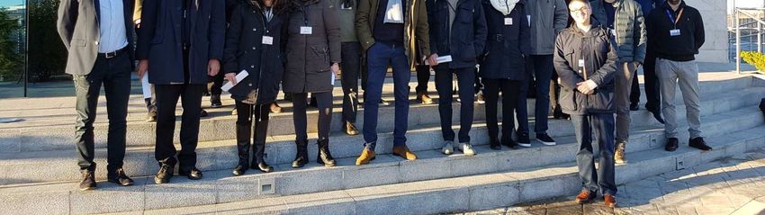
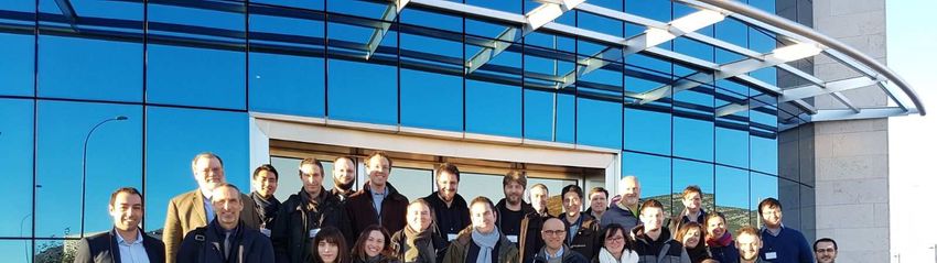
Annual meeting 2018
@ EDSS in Puertollano
ReDSHIFT status
1.   First full mapping of the LEO-to-GEO space (by IFAC, University of Thessaloniki
     and PoliMI) with an un-precedented level of detail with the aim of finding
     preferential routes for de-orbiting (“de-orbiting highways”) or stable zone.
2.   The dynamical maps are and are now fully available at the project website
     (http://redshift-h2020.eu/results), along with all the related papers.
3.   The software allowing the exploitations of the dynamical findings (de-orbing
     strategies and maneuvers, both with and without sails, + expected
     flux/collision probability) is completed and will be freely available, on a web
     version, on the project website (See the presentation on Wednesday).
4.   3D printing and testing on going (See the presentation by Beck on Wednesday).
5.   Legal and normative analysis ongoing (See the presentation by Kim this
     afternoon).
LEO to GEO resonance mapping
           as a preferential route to de-orbiting
• A variable grid was defined
   from LEO to GEO.
• Several tens of millions of
   orbits were propagated.
• Different computational
   models, including all the
   relevant gravitational and
   non gravitational
   perturbations, were use for
   the three regimes (LEO, MEO,
   GEO).
• All the maps are currently
   available and downloadable
   from:
http://redshift-h2020.eu/results
LEO: resonance mapping as a
        preferential route to de-orbiting
Maximum eccentricity map for objects with enhanced A/M = 1 m2/kg
LEO to GEO resonance mapping
as a preferential route to de-orbiting

LEO to GEO resonance mapping
       as a preferential route to de-orbiting

Asteroid resonances

Orbital distribution of main
belt asteroids (green),
Intermediate Mars Crossers
(blue) and NEOs (white, red
and magenta)
(From: B. Bottke et al.,
Understanding the
distribution of NEAs).
LEO: resonance mapping as a
           preferential route to de-orbiting
Residual lifetime for objects with enhanced A/M = 1 m2/kg
MEO: resonance mapping as a
            preferential route to de-orbiting
                                               ∆V needed to de-orbit a Galileo vs the time needed
                                               to re-entry, for all 1-burn (dark) and 2-burn
                                               Hohmann (light grey) maneuvers found. The
                                               blue/red curve is the pareto front. A number of
                                               possible solution with ∆V ≤200 m/s and Tr ≥60 y can
                                               be noticed.

 Maximum Eccentricity Map for circular MEOs
with i = 56◦ (A/M= 1 m²/kg). White regions
indicate that the eccentricity needed to re-entry
into the atmosphere is reached within 120 y.
Grid Definitions
Tesseral Maps
Main grid: a - λ (201x201) > 4 Million
Parameters: e, i, A/m (5x11x2)
Disposal Maps
Main grid: ω - Ω (201x201) > 36 Million
Parameters: e , i, A/m (5x91x2)
Action Maps
Main grid: e - i (201x201) > 12 Million
Parameters : a, (Ω, ω), A/m (3x50x2)
Orbits propagated > 50 Million
Dynamical indicators:
Bounded
Re-entry
11GEO: Tesseral resonance
A/m = 0.012 m2/kg
e0 = 0.01
i0 = 10 deg i0 = 60 deg
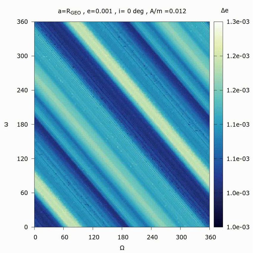
12GEO: Disposal maps
A/m = 0.012 m2/kg
e0 = 0.001 e0 = 0.2
Diam(e) Diam(e)
13GEO: Eccentricity-Inclination space
Re-entry
Bounded
14Modulating solar sailing
Different sail deorbiting strategies
studied by PoliMI and LUXSPACE.
Active attitude control solar sailing:
the deorbiting is obtained by spiralling
inward on a circular orbit
Passive attitude control solar sailing:
the deorbiting is obtained by
increasing the eccentricity of the orbit.
Modulating (on-off) attitude control
(through a variable sail geometry):
deorbiting can be achieved even from
MEO and GEO as long as the sail
attitude can be changed every 6
months
Requirements (colour bar) in terms of
effective area-to-mass (cRA/m) for
deorbiting time of 25 years with
modulating attitude control for the
sail.
16/01/2018 MEETING IN DEIMOS PUERTOLLANO WP4 - SOLAR SAIL DYNAMICS 15LEO to GEO resonance mapping
as a preferential route to de-orbiting
The natural dynamics is enhanced via impulsive manoeuvres, solar
and drag sailing and a combination of manoeuvres and solar and
drag sailing.
For LEO disposals:
• compute the possible displacements in (a,e,i) for a given ∆V provided in input, in order
to identify the most suitable final orbit that can be achieved with that ∆V.
• The maximum ∆V considered for the simulation is the one corresponding to a direct re-
entry manoeuvre down to 80 km of altitude.
• In this way, all the possible target orbits are selected and, among them, the one that
will naturally evolve toward re-entry in a time less than 50 years are chosen.
• For all these cases, the required ∆V is computed as a single burn manoeuvre in case the
two orbits are intersecting.
• A solar radiation pressure-augmented case, (A/M= 1 m²/kg) is considered too.
• In this case the corresponding resonant inclination are targeted.
• This corresponds to a two-phase deorbiting strategy: a relatively small manoeuvre is
performed to reach a resonance where the atmospheric drag or the solar radiation
pressure can then be exploited to re-enter by means of a passive stabilised sail.LEO to GEO resonance mapping
as a preferential route to de-orbiting
The natural dynamics is enhanced via impulsive manoeuvres, solar
and drag sailing and a combination of manoeuvres and solar and
drag sailing.
Minimum-cost re-entry solutions,
Results for the direct re-entry solutions.
a0 = RE +1520 kmLEO to GEO resonance mapping
as a preferential route to de-orbiting
The natural dynamics is enhanced via impulsive manoeuvres, solar
and drag sailing and a combination of manoeuvres and solar and
drag sailing.
For MEO and GEO disposals:
• Given the initial post-mission orbit and the maximum available ∆V on-board the
satellite, the reachable orbital element domain is computed via a single manoeuvre.
• From all the reachable orbits, we exclude orbits in GEO protected region and a MEO
protected region (that was defined in ReDSHIFT around the GNSS satellite
constellations).
• The required manoeuvre sequence to reach each one of this target orbit is computed.
In the MEO case, a transfer with 1 and 2-burn manoeuvre given at the characteristic
points of the orbit (i.e. apogee, perigee, nodes) is performed.
• In the GEO case, the optimal transfer between the last operational orbit and any of the
possible target orbits is computed with a 2-burn manoeuvre, through the Lambert
problem solved on a grid of initial and final transfer times.
• The best results are chosen by representing the Pareto front solutions in terms of the
minimum ∆V and re-entry time.3D printing of spacecraft parts and shields at University of Southampton
3D printed material: tests

Shields designed and tested by PHS
Space and University of Padova.
The 3D printed parts are undergoing a
series of tests:
• D4D at DLR
• Radiation and hypervelocity impact
   tests at Univ. of Padova.
3 prototype spacecraft
                       • 3 spacecraft
                         assembled/printed at Elecnor
                         Deimos Satellite Systems

• The 3 spacecraft
  underwent launch
  vibration tests by
  EDSS
3 prototype spacecraft
• The 3 spacecraft underwent
launch vibration tests
• All the spacecraft passed the
tests.
• The outcome shall
be used to optimize
the design of a
spacecraft fully
optimized for 3D
printingD4D Tests • Test campaign performed at the DLR L2K facility, by the Belstead Ltd. and the DLR teams (details in Beck’s presentation on Wednesday).
D4D Tests – A number of “firsts”

• First tests of aluminium thin structures:
    • Top hat, Plate, CubeSat Structure,
       Reaction Wheel Housing.
• First demise test of a full CubeSat
  mockup:
    • Demise expected, but maybe not as
       easily as previously thought:
         • Structure melts;
         • steel rods for mounting can
            support structure
         • GFRP electronics cards more
            robust than expected
D4D Tests – A number of “firsts”
• First demise test of an engineering
model of a reaction wheel:
• demise process very different from
models
• Many small parts produced
• Not quite as bad for demise as it
looks…
• But massive steel objects are clearly
an issueReDSHIFT software tool
• Based on the
openSF
simulation
framework
• Designed and
assembled and at
Deimos Space.
• See presentation
on WednesdayWhat’s next?
1. Complete the hypervelocity test campaign on the 3D printed shields re-
design of the shields by Padova and PHS Space Ltd. and choice of the best one.
2. 3D printed optimized re-design of the spacecraft by SOTON and EDSS.
3. 3D print of the of the final spacecraft at SOTON.
4. New vibration test campaign and qualification.
5. New long term evolution campaign by TUBS and IFAC to verify the
effectiveness of some of the results, in terms of benefits to the debris
environment.
6. Complete software and interface between the modules: web-version made
available to public (See the presentation on Wednesday). .
7. Legal and normative analysis of the final results by the University of Cologne
(See the presentation by Kim this afternoon). .Final ReDSHIFT conference We are planning a Final ReDSHIFT conference to be held in Florence at the end of 2018, in the Auditorium di Santa Apollonia.
Revolutionary Design of Spacecraft through
           Holistic Integration of Future Technologies

                       HTTP://REDSHIFT-H2020.EU/
The research leading to these results has received funding from the Horizon 2020 European Union Framework
Programme for Research and Innovation (H2020-PROTEC-2015) under REA grant agreement n. [687500]- ReDSHIFT
You can also read