Thermal Engineering for the Beagle 2 Mars Lander Surface Operations - Dr Bryan Shaughnessy Rutherford Appleton Laboratory Space Science and ...
←
→
Page content transcription
If your browser does not render page correctly, please read the page content below
Thermal Engineering for the Beagle 2
  Mars Lander Surface Operations

             Dr Bryan Shaughnessy
        Rutherford Appleton Laboratory
   Space Science and Technology Department

          b.m.shaughnessy@rl.ac.uk

          http://www.sstd.rl.ac.uk/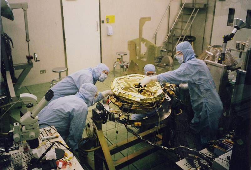
Acknowledgment

h Dr Simon Peskett, who preceded me as lead thermal engineer
  on Beagle 2 until he left RAL at the end of 2001.
Mission Overview

• Launched June 2003 aboard ESA’s Mars Express – to look
  specifically for signs of life. Seven month Cruise, followed by
  five day Coast (no telemetry available)

• Landing site in the Isidis Basin (11°N 90°E)

• Early spring northern hemisphere (Ls = 322°). Baseline
  mission of 180 Sols (to Ls = 60°)

• Landing planned for Christmas morning 2003 but no
  communication achieved with Beagle 2
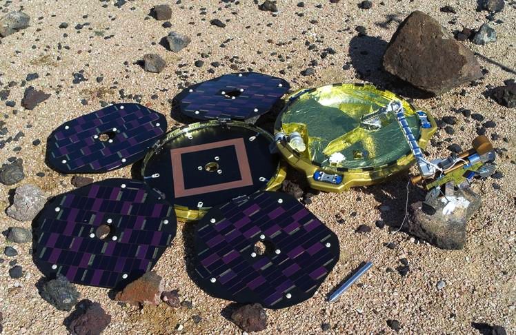
Landed Configuration
                                  All Rights Reserved Beagle 2

Lander model on the NASA Johnson Space
Centre Mars Simulation Surface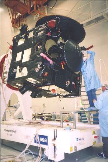
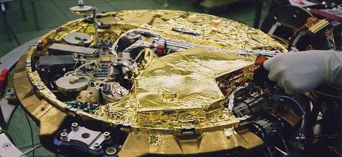
Inside the Lander

     PAW                            Instrument arm

Battery and                                  Gas
Electronics                                  Analysis
                                             Package
              Aeroshell interface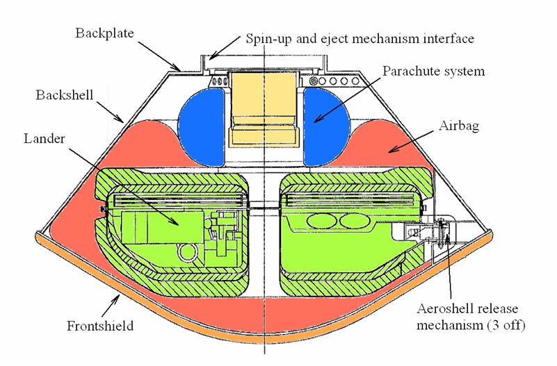
Beagle 2 Science Summary

• Beagle 2 was packed like a tourist’s suitcase!
• Examine soil, rocks, and atmosphere for evidence of
  life
    • Instrument arm
    • Beagle’s ‘PAW’ and the ‘Mole’
    • Gas Analysis Package
• Martian weather reports
• Age, chemistry, and composition of the Mars surface
• Cameras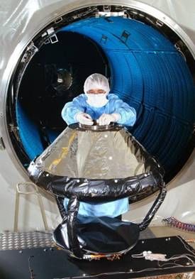
Journey to Mars - the Probe
     Backplate         Spin-up and eject mechanism interface
                                       Parachute system
Backshell
                                             Airbag
Lander

                                           Aeroshell release
    Frontshield                            Mechanism (3 off)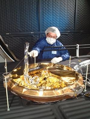
Mars Express

                               Integration of Beagle 2
                               multi-layer insulation at
                               the Baikonur Cosmodrome

All Rights Reserved Beagle 2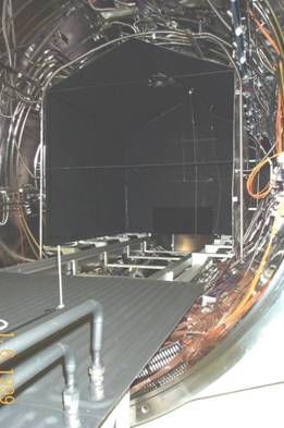
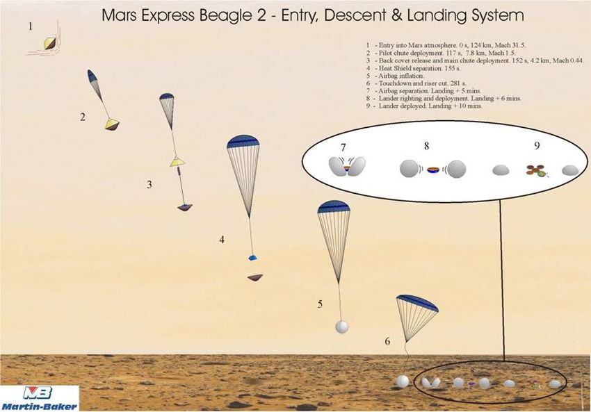
Landing Sequence
Lander Boundary Conditions

• Direct and diffuse solar radiation

• Radiative losses to effective sky temperature

• Radiative and conductive losses to surface

• Convective losses to local environment
Mars Environment
• Environmental conditions influenced by the level of dust
  (optical depth) in the atmosphere.

• Time of landing (Ls = 322°) shortly after the dust storm
  season. Optical depths:
   • Can exceed 5.0 during dust storm
   • 1.0 measured by Viking, decreasing to 0.5 through spring
     and summer
   • 0.2 measured by Mars Global Surveyor

• Surface temperatures: ~ 0 °C early afternoon to ~ -100 °C
  just before dawn

• Sky temperature: -100 °C to -150 °C

• Wind speeds typically less than 10 m/s
Environmental Design Cases
COLD HOT
PARAMETER BOL EOL BOL EOL
Aerocentric longitude (°) 322 60 322 60
Latitude (°) 31 31 0 0
Optical depth (-) 2.0 0.7 0.2 0.2
Wind speed (m/s) 10 10 0 0
Interface with surface ‘raise ‘raise ‘fir ‘fir
d’ d’ m’ m’
Dust coverage (%) - 100 - 24Mars Environment
300
275
250
Temperature (K)
BOL COLD
BOL HOT
225
EOL COLD
EOL HOT
200
175
150
0 2 4 6 8 10 12 14 16 18 20 22 24
Time since local noon (Martian hours)
Assumed surface temperatures
(taken from Mars Climate Database)Requirements
hMinimize energy required by survival and operational
heaters
hMaintain temperatures within applicable limits:
NON-OPERATIONAL OPERATIONAL
(°C) (°C)
UNIT MIN MAX MIN MAX
Battery - - -30 45
Common electronics - - -50 55
Transceiver -65 55 -65 55
Gas Analysis Package -65 40 -40 30
Instrument arm -100 125 -60 30
Solar arrays -120 - - 40Thermal Design Concept h Thermally isolate battery from structure (low conductance mounts; radiative shielding) h Thermally couple electronics to battery (~ 8W stand-by dissipation) h Foam insulation h Low-emissivity finishes h Use of survival heaters on battery and elsewhere where necessary h Qualify components to accommodate wide temperature fluctuations
Preliminary Trade-off (1/2)

h Two approaches were considered for keeping battery warm:

   hRadioisotope heater unit (RHU) coupled to battery
     h8.5 W dissipation

   hA solar absorber unit (SAU) architecture to optimize
    absorption of incident solar radiation together with a phase
    change material (PCM):

      hTinox solar absorber (αs > 0.94, ε < 0.05)
      h1.5 kg water PCM
Preliminary Trade-off (2/2)
h Conclusions of trade-off:
hBoth approaches feasible for Lander thermal design
hRHU approach less sensitive to variations in Lander design
parameters, but had narrow design margins in some areas
hOther technical difficulties with RHUs (e.g., heat rejection
system during Cruise/Coast)
hConclusion was to focus on development of the SAU
approachRefinement of Design (1/2) h The use of different solar absorber materials and PCM options was considered. h Solar absorber materials: hTinox (αs > 0.94, ε < 0.05) hGermanium x VDA x Kapton (αs ~ 0.6, ε ~ 0.05) hHybrid Tinox/Germanium h PCM options: hNone h0.5 kg and 0.86 kg water h0.5 kg and 0.77 kg dodecane wax (melting point ~ - 10 °C)
Refinement of Design (2/2)

h Under cold conditions water PCMs could stay frozen

h A 0.77 kg dodecane PCM had improved response compared
  with 0.5 kg water, but increased mass was a major concern

h 0.5 kg dodecane PCM was marginal at BOL cold conditions

h Electronics may exceed upper temperatures in hot cases if
  high-absorptivity (Tinox) absorber used

h A Germanium x VDA x Kapton SAU architecture without a
  PCM was initially baselined
Detailed Thermal Design
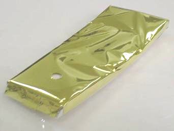
Detailed Thermal Design
h Low conductance structure (glass-fiber reinforced plastic
  instead of aluminium honeycomb).

h Inner and outer surfaces of Lander structure gold coated

h Solar absorber finish now gold coated kapton

h Instrument arm wrapped in aluminized tape

h Software controlled heaters on battery, transceiver, and a
  small number of locations in Lander.
Solar Absorber Unit

                      All Rights Reserved Beagle 2
Thermal Balance Testing
Lander test Lander test Probe test model,
shroud model, RAL, September
RAL, May 2002 2002Lander Test Requirements
Ideal Specified
Lander Model •Complete •With lid, but no solar arrays
•Partial instrument arm
Surface •Sandy/rocky – like landing site •Temperature controlled
•Temperature cycling between panels:
-100 and 0 °C oBeneath Lander
oSurrounding Martian
surface
Atmosphere •~ 7 mbar CO2 •~ 7 mbar CO2
•Temperature cycling between •Temperature not controlled
-100 and 0 °C •Winds up to 10 m/s
•Winds up to 10 m/s
Sky-view •-135 °C •-100 °C
Solar simulator •Moving beam •Vertically
fixed beam
•0 – 600 W/m2 intensity •0 – 600 W/m2 intensityLander Test Implementation
Closing Flight Model Lander

All Rights Reserved Beagle 2
Conclusions

h Thermal design for the Martian environment is a great
  challenge

h A thermal design approach which did not require the use
  of RHUs was developed for Beagle 2

h The thermal design was verified by extensive testing at
  RAL
Is there life on Mars?
You can also read