Understanding ballistics - A PRIMER FOR COURTS
←
→
Page content transcription
If your browser does not render page correctly, please read the page content below
UNDERSTANDING BALLISTICS: A PRIMER FOR COURTS                         1

                                                Understanding
                                                ballistics
                                                A PRIMER FOR COURTS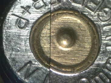
2                                                               UNDERSTANDING BALLISTICS: A PRIMER FOR COURTS

This primer is produced by the Royal Society
and the Royal Society of Edinburgh in conjunction
with the Judicial College, the Judicial Institute and
the Judicial Studies Board for Northern Ireland.

Understanding ballistics: a primer for courts
Issued: May 2021 DES7510
ISBN: 978-1-78252-485-4
© The Royal Society

The text of this work is licensed under the terms of the
Creative Commons Attribution Licence, which permits
unrestricted use, provided the original author and
source are credited. The licence is available at:
creativecommons.org/licenses/by/4.0

Images are not covered by this license.
Requests to use them should be submitted
to the below address.

To request additional copies of this document
please contact:

The Royal Society
6 – 9 Carlton House Terrace
London SW1Y 5AG
T +44 20 7451 2571
E law@royalsociety.org
W royalsociety.org/science-and-law

This primer can be viewed online at
royalsociety.org/science-and-law

Image credits:
Figures 1 – 25: National Ballistics Intelligence Service (NABIS).
Figures 26 and 27: Chemical Ballistics Research
Group, Liverpool John Moores University.
UNDERSTANDING BALLISTICS: A PRIMER FOR COURTS                   3

Contents
Introduction and scope                                         6

1. Ballistics		                                                 8
  1.1   Firearms types and operation                            8
  1.2 Ammunition                                               14
  1.3 Calibre                                                  21
  1.4 Internal ballistics                                      22
  1.5 External ballistics                                      22
  1.6 Terminal ballistics                                      24

2. Scene interpretation                                        25
  2.1 Ricochet                                                 25
  2.2 Trajectory                                               26
  2.3 Damage and range interpretation                          26
  2.4 Wound interpretation                                     26

3. Microscopy                                                  27
  3.1 Introduction                                             27
  3.2 Identification of weapons                                29
  3.3 Comparison of fired Items                                31
  3.4 Linking ballistic material to a recovered weapon         32
  3.5 The Integrated Ballistics Identification System (IBIS)   32

4. Mechanical condition                                        34
  4.1 Trigger pressures                                        34
  4.2 Safety devices, external and internal                    35
  4.3 Unintentional discharge                                  37
4                                      UNDERSTANDING BALLISTICS: A PRIMER FOR COURTS

5. Gunshot residue                                                               38
    5.1 What is gunshot residue?                                                 38
    5.2 Sampling                                                                 38
    5.3 Analysis                                                                 41
    5.4 Classification                                                           42
    5.5 Interpretation                                                           44

6. Firearms classification                                                       47

7. The future                                                                   52

Appendices		                                                                     54
    Appendix 1: supplementary tables                                             54
    Appendix 2: case examples                                                    57

Glossary		                                                                      59

Bibliography		                                                                   79

Acknowledgements                                                                 81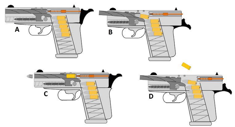
UNDERSTANDING BALLISTICS: A PRIMER FOR COURTS                                               5

Science and the law primers
Foreword
The judicial primers project is a unique collaboration between members of the judiciary,
the Royal Society and the Royal Society of Edinburgh. The primers have been created
under the direction of a Steering Group initially chaired by Lord Hughes of Ombersley
who was succeeded by Dame Anne Rafferty DBE, and are designed to assist the
judiciary when handling scientific evidence in the courtroom. They have been written
by leading scientists and members of the judiciary, peer reviewed by practitioners and
approved by the Councils of the Royal Society and the Royal Society of Edinburgh.

Each primer presents an easily understood, accurate position on the scientific topic in
question, and considers the limitations of the science and the challenges associated
with its application. The way scientific evidence is used can vary between jurisdictions,
but the underpinning science and methodologies remain consistent. For this reason
we trust these primers will prove helpful in many jurisdictions throughout the world
and assist the judiciary in their understanding of scientific topics. The primers are not
intended to replace expert scientific evidence; they are intended to help understand
it and assess it, by providing a basic, and so far as possible uncontroversial, statement
of the underlying science.

The production of this primer on understanding ballistics has been led by His Honour
Clement Goldstone. We are most grateful to him, to the Executive Director of the Royal
Society, Dr Julie Maxton CBE, the Chief Executive of the Royal Society of Edinburgh,
Dr Rebekah Widdowfield, and the members of the Primers Steering Group, the Editorial
Board and the Writing Group. Please see the back page for a full list of acknowledgements.

Sir Adrian Smith                                Dame Anne Glover
President of the Royal Society                  President of the Royal Society of Edinburgh
6                                                  UNDERSTANDING BALLISTICS: A PRIMER FOR COURTS

Introduction and scope
The aim of this primer is to present:

1. a scientific understanding of current practice for forensic ballistics and gunshot
   residue (GSR) examination used within a forensic science context;

2. guidance to the judiciary in relation to the strengths and limitations of current
   interpretation and evaluations that can be made, in particular (a) the elements of the
   work that are subjective in nature and (b) the linking of bullets and cartridge cases to
   a specific weapon.

The primer has been laid out in sections that provide the basic information relating
to the different elements of firearms and GSR analysis used in forensic science.

In addition, the primer includes references highlighting areas for further reading,
appendices and a glossary of terms.

Ballistics is the study of projectiles in flight; the word is derived from the Greek,
ballein, meaning ‘to throw’. Forensic ballistics is commonly accepted as any scientific
examination relating to firearms and is performed with the intention of presenting
the findings in court. This commonly includes providing an opinion as to whether
the ammunition components may be linked to the weapon which discharged them,
establishing range of fire, identifying entry and exit wounds, interpreting damage caused
by gunshots and examining the mechanical condition of guns. Ironically, calculating the
properties of a bullet or projectile in flight, true ballistics, is hardly ever used, although in
some rare cases it is a vital part of the firearms expert’s armoury. Somewhat unusually
in forensic science in the UK, ballistic experts are expected to give opinions on the
classification of firearms, under the many pieces of complex firearms legislation.

The study of gunshot residue, or GSR, is normally regarded as a discipline separate from
forensic ballistics but it is closely linked and is within the scope of this primer.

History
In some interesting early examples, interpretation of material recovered following a
shooting was used to draw logical conclusions. One famous example followed the
death of a Union General, John Sedgwick, in the American Civil War. He chided his men
for cowering from Confederate snipers, firing at 1000 yards, hubristically declaring “one
couldn’t hit an elephant at that range”, before he was killed instantly by a bullet through
his head. The explanation was found when the offending bullet was removed and was
UNDERSTANDING BALLISTICS: A PRIMER FOR COURTS                                               7

discovered to be hexagonal in shape. This confirmed that it could only have been fired
from a British Whitworth rifle, a weapon capable of exceptional accuracy for its day and
sold in numbers to the Confederate side.

Another early example includes a ‘cloth patch’ which had been wrapped around a
musket ball and recovered from the wound of a murder victim (wrapping a ball in
a greased cloth patch improved accuracy). The ‘cloth patch’ had been torn from a
suspect’s handkerchief, thereby linking him conclusively to the murder.

The first documented forensic ballistics case in the UK was in 1835. Henry Goddard, a
Metropolitan Police officer, was investigating a murder where the victim had been shot
with a lead ball projectile. Upon inspection of the recovered projectile, Goddard noticed
a casting mark left by the mould which had formed the lead ‘bullet’. A suspect was
identified and a bullet mould recovered from his home. Test samples from the suspect’s
mould compared with the casting marks on the recovered projectile allowed Goddard to
confirm that the fatal bullet had been produced from the suspect’s mould. The suspect
was convicted of the murder.

In the UK, what we would now recognise as forensic ballistics began in the 1920s when
two pioneers, Robert Churchill and Major Gerald Burrard, started to examine bullets and
cartridge cases to see if they could be linked to specific weapons. One of the first cases in
the UK to use forensic ballistics was the infamous murder of PC William Gutteridge in 1927
(PC Gutteridge had been shot through the eyes, possibly because of superstitious beliefs).
Robert Churchill was able swiftly to match the bullets to a gun found at a suspect’s house.
Although the comparison microscopes were crude by today’s standards, the fundamental
principles of comparison microscopy were established by these early pioneers. After the
Second World War, the Forensic Science Service consolidated all firearms examination in
England and Wales, and was largely responsible for setting the foundations for modern
forensic ballistics examinations in the UK. Nevertheless, although technology has had an
impact on the work, enabling, for example, rapid searching of bullets and cartridge cases,
most forensic ballistic work remains little different from that which Churchill and Burrard
practised nearly 100 years ago.
8                                                  UNDERSTANDING BALLISTICS: A PRIMER FOR COURTS

1. Ballistics
1.1 Firearms types and operation
There are many different types of firearms, but only certain types are commonly
used in crime in the UK. At the time of publication, handguns and sawn-off shotguns
predominate, with over 90% of serious armed crime involving these weapon types. This
section thus concentrates on them, although it does also refer to guns such as sub-
machine guns and assault rifles, which, although much less common, are sometimes
used by criminals.

Self-loading pistols (Figure 1)                    FIGURE 1
Most self-loading pistols consist of a
frame or receiver with a reciprocating            A self-loading pistol.
slide. Sometimes the barrel is fixed to the
receiver; sometimes this is a separate
part which moves during the firing cycle.
Generally, self-loading pistols operate
using a spring-operated box magazine, the
bulk of which is fitted into the handle of
the pistol. They fire one cartridge for each
pull of the trigger, with fired cartridge cases
being ejected from the weapon.

Self-loading pistol operation (Figure 2)
During normal operation, a magazine is filled with a number of cartridges and is inserted
into the magazine well. The pistol’s slide is pulled to the rear and released; as it travels
forward, under the force of a spring, the top cartridge is stripped from the magazine and
fed into the chamber. The pistol is now cocked and loaded. From this point, assuming
any safety catch is set to the fire position, pressure on the trigger will fire the weapon.

On firing, recoil forces cause the cartridge case to be thrust back against the slide,
which is pushed to the rear, allowing the empty, fired, cartridge case to be ejected from
the weapon. As the slide travels forward again, propelled by a mainspring, it strips the
top cartridge from the magazine and feeds it into the chamber. The hammer or striker
remains cocked and the trigger must be released and pulled again before the newly
chambered cartridge can be fired.
UNDERSTANDING BALLISTICS: A PRIMER FOR COURTS                                                  9

This type of pistol will fire a single cartridge for each pull of the trigger. Once the
magazine has been emptied, the pistol’s slide will be held at the rear, demonstrating to
the user that the weapon is empty.

 FIGURE 2

Self-loading (semi-automatic) pistol operation cycle.

A. Gun at rest with loaded magazine containing live cartridges.
B. Slide is pulled rearwards and released forward, chambering a live cartridge from the
   magazine and cocking the hammer.
C. The trigger is pulled; the hammer strikes the firing pin, which in turn detonates the
   live cartridge, forcing the bullet down the barrel.
D. Recoil forces slide rearwards, extracting the spent casing. On the forward movement,
   a new live cartridge is reloaded from the magazine.

Illustration created by Christopher Poole, National Ballistics Intelligence Service (NABIS).
10                                                 UNDERSTANDING BALLISTICS: A PRIMER FOR COURTS

Revolvers (Figure 3)                               FIGURE 3
Revolvers derive their name from
                                                  A revolver.
the revolving cylinder that holds the
cartridges. The cylindrical, rotating part of
a revolver contains separate chambers
revolving round a central axis to align the
individual chambers with the rear of the
barrel for firing. Cylinders typically hold six
cartridges, but there are exceptions.
                                                   FIGURE 4
Cartridge-firing revolvers generally come
in one of three forms:                            Gate-loading
                                                  revolver.
•    Solid frame revolvers with the cylinder
     held in the frame, fixed behind the
     barrel. These are normally loaded via a
     slot in the rear of the frame known as a
     gate. These are known as gate-loading
     revolvers (Figure 4).
                                                   FIGURE 5
•    Hinge frame revolvers (Figure 5),
     where the frame is hinged usually            Hinge frame
     at the front of the frame below the          revolver.
     barrel. Cartridges are loaded into the
     weapon’s chambers after the frame is
     broken open.

•    Solid frame revolvers, with a swing-
     out cylinder (Figure 6). The cylinder
     is mounted on an arm, known as the            FIGURE 6
     crane, which normally swings out to
     the left-hand side of the weapon.            Swing-out
                                                  cylinder revolver.
UNDERSTANDING BALLISTICS: A PRIMER FOR COURTS 11 Revolver operation Revolvers are designed to be fired in single- or double-action mode. In single-action mode, the hammer is manually cocked. As the hammer is raised, the revolver’s cylinder rotates automatically to bring the next cartridge to be fired beneath the hammer. Once cocked, pressure on the trigger fires the weapon. In double-action mode, as the trigger is pulled, the cylinder rotates automatically and the hammer is raised almost to its rearmost position, from which point it discharges the weapon. The fired cartridge cases remain within the weapon, unless removed by the firer. Shotguns (Figure 7) There are four main types of shotgun: single-barrelled weapons, double-barrelled weapons, pump-action weapons and self-loading weapons. Double-barrelled and single-barrelled weapon operation Most double-barrelled shotguns have a so-called break action. This means that the weapon hinges just forward of the firing mechanism, exposing the rear of the barrels. In side-by-side weapons, the barrels are laid alongside each other; in ‘over and under’ shotguns, the barrels are one above the other. FIGURE 7 Typical double-barrelled shotgun (top) and a shortened or ‘sawn-off’ single-barrelled shotgun (bottom).
12                                                  UNDERSTANDING BALLISTICS: A PRIMER FOR COURTS

Some double-barrelled shotguns have one trigger; some others have two. Conventionally
in double-trigger guns, the front trigger fires the right-hand side or lower barrel. On some
single-trigger guns, the order of firing is set; in others, the order is determined by the firer,
using a switch on the safety catch. The selected barrel is fired first; pulling the trigger
again will fire the other barrel.

Some weapons have exposed hammers and others have internal hammers. Weapons
fitted with an external hammer must be manually cocked before the weapon will
discharge. Weapons with internal hammers are cocked automatically as the weapon
is opened to be loaded.

Once a cartridge is loaded into the chamber and the weapon is closed and cocked and
any safety catch is set to the fire position, pulling the trigger will fire the weapon.

Single-barrelled weapons are identical in operation but have only one barrel and
one trigger.

Pump-action and self-loading weapon operation
Both these types of weapon have a single barrel. They are magazine-fed and the
magazine is usually a tube beneath the barrel. Cartridges are fed into the magazine
through a port on the underside of the weapon. Cartridges are chambered from the
magazine either by operation of a pump handle (pump-action) or by manual operation of
a bolt (self-loading). Once loaded, pulling the trigger will fire any chambered cartridge.

A pump-action weapon is reloaded by operating the pump handle. The fired cartridge
case is ejected from the chamber and a fresh cartridge from the magazine is loaded.
Releasing and pulling the trigger will fire this chambered cartridge. A self-loading
weapon ejects the fired cartridge case automatically from the chamber and feeds a
fresh cartridge from the magazine into the chamber; again, pulling the trigger will fire
the freshly chambered cartridge.
UNDERSTANDING BALLISTICS: A PRIMER FOR COURTS                                               13

Sub-machine guns and assault rifles (Figure 8)
Neither type of weapon is commonly seen in gun crime in the UK. The main difference
between the two is that the sub-machine gun uses pistol ammunition and the assault
rifle an intermediate cartridge, ie one lower powered than a normal rifle cartridge.
Both weapon types are generally ‘selective-fire’ weapons, in that they can fire single
shots, each requiring a separate pull on the trigger for each shot, or ‘full-auto’, where
the gun will continue to discharge for as long as the trigger is depressed and there is
ammunition in the magazine.

 FIGURE 8

The AK47 assault rifle (left) and MAC-10 sub-machine gun (right),
both capable of fully automatic fire.
14                                                UNDERSTANDING BALLISTICS: A PRIMER FOR COURTS

1.2 Ammunition                                    FIGURE 9
Metallic, centrefire, bulleted cartridge
construction (Figure 9)                          Metallic bulleted cartridges
Conventional metallic, centrefire, bulleted      in various calibres.
cartridges consist of four constituent parts:
a cartridge case, propellant powder, a
primer and a projectile (Figures 10 and
11). The primer, the ignition system of the
cartridge, sits in the base of the cartridge
case; the propellant is housed inside the
cartridge case; and the projectile sits in the
cartridge case mouth. In common parlance,
people often refer to a round of ammunition
as a ‘bullet’ whereas technically ‘bullet’
refers only to the projectile.

NB. In this Primer for Courts, ‘bullet’           FIGURE 10
and ‘projectile’ should be regarded as
interchangeable.                                 The components of a bulleted cartridge.

On firing a bulleted cartridge, the cartridge
case expands slightly, forming a tight gas
seal at the rear of the barrel. This helps to
maintain sufficient pressure to propel the                                         Bullet
bullet down the barrel at optimum velocity.

                                                                                   Case

                                                                                   Propellant

                                                                                   Flash hole
                                                                                   Primer

                                                 Illustration created by Christopher Poole,
                                                 National Ballistics Intelligence Service (NABIS).
UNDERSTANDING BALLISTICS: A PRIMER FOR COURTS 15 Production of ammunition Conventional centrefire cartridges can be produced in one of two ways: 1. Factory made. The cartridges are assembled in a factory. 2. Hand-loaded/reloaded. The spent primer is removed from a previously fired cartridge case. A replacement live primer is added to this cartridge case, with a measured quantity of propellant and a projectile, to form a new round of ammunition. Hand-loaded/reloaded cartridges are assembled somewhere other than in a conventional factory, generally at home. The constituent parts of the cartridges can be bought separately and assembled to form whole rounds of ammunition. (This should not be confused with the term ‘reloading’, which can apply to changing magazines or inserting cartridges into a gun after discharge.) Bullet styles Bullets for use in cartridges come in a number of styles. These are categorised by shape, material and composition. Most bullets are made of lead or have lead in their composition. Some bullets have harder metal jackets, usually copper alloy or copper-plated steel. The jackets of bullets may cover all (full-metal jacket) or part (semi-jacketed) of the bullet. In the former, the base of the bullet is exposed, showing the (lead) core. In the latter, the base of the bullet is covered, exposing either a small amount of lead at the nose (soft-point) or a hole or depression (hollow-point). These are designed to expand on impact. FIGURE 11 Cartridge cases, bullets, propellant and primers.
16                                                             UNDERSTANDING BALLISTICS: A PRIMER FOR COURTS

How a centrefire cartridge works (Figure 12)
In a centrefire metallic cartridge, the firing pin strikes the primer in the centre of the base of
the cartridge. The priming composition explodes and a jet of flame passes through the flash
hole in the cartridge case and ignites the propellant powder within the body of the cartridge
case. The propellant powder burns, producing a large volume of gas. This expanding gas
pushes the bullet out of the cartridge case and down the barrel of the firearm.

 FIGURE 12

Centrefire primer detonation.

                                                                                Propellant

                                                                                Flash hole
                                                                                Explosive
                                                                                compound

                                                                                Firing pin

Illustration created by Christopher Poole, National Ballistics Intelligence Service (NABIS).

How a rimfire cartridge works (Figure 13)
Rimfire cartridges are made from a thin sheet of metal folded to form the shape of a
cartridge. The priming composition sits in the base of the cartridge case and, during
manufacture, is spun into the rim.

Rimfire cartridges sit in the weapon’s chamber, rims against the back. The firing pin strikes
the rim at the base of the cartridge and crushes the rim against the rear of the chamber,
so crushing the priming composition between the fold of metal at the base of the cartridge.
A 0.22 cartridge is an example of a rimfire cartridge and is one of the most common
calibres worldwide. See Glossary and section 2.3 for further discussion on calibre.
UNDERSTANDING BALLISTICS: A PRIMER FOR COURTS 17
FIGURE 13
Rimfire primer detonation.
Bullet
Cartridge
Propellant
case
Propellant Explosive
compound
Firing pin
Illustration created by Christopher Poole, National Ballistics Intelligence Service (NABIS).
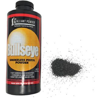
Propellant powder (Figure 14) FIGURE 14
Propellant powder comes in a variety
of forms and chemical compositions Smokeless propellant powder
depending upon the purpose for which
it is intended. (This is dealt with in more
detail in Chapter 5.)
Propellant powder burns rather than
explodes, but it burns very rapidly when
confined in a cartridge case in the
barrel of a weapon. The rate of burning
increases as pressure increases. The
pressure in the barrel drops when the
projectiles exit the muzzle (the front end
of the barrel).18 UNDERSTANDING BALLISTICS: A PRIMER FOR COURTS
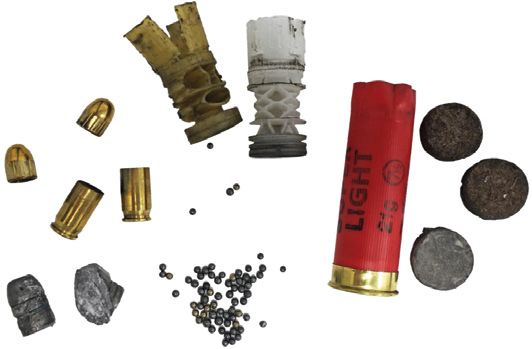
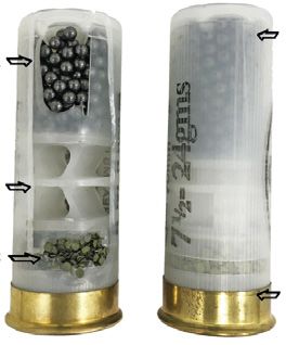
Shotgun cartridge construction FIGURE 15
(Figures 15 and 16)
Conventional shotgun cartridges consist Shotgun cartridges, common 12-gauge
of five constituent parts: a cartridge case, and 0.410 calibre examples.
propellant, primer, wad and a quantity of
shot pellets or a single projectile.
While generally made of lead alloy,
shotgun pellets may be made of other
materials, including steel, bismuth and
tungsten. Generally, shot are spherical.
Cartridge cases
Shotgun cartridge cases consist of a
plastic or cardboard tube, the rear of
which is covered with a metal cap-like FIGURE 16
structure known as the head. Although
generally made of steel, it is often plated A shotgun cartridge:
with brass. This portion of the cartridge A. Lead shot
case houses the primer assembly and
B. Plastic wad
is generally marked with a headstamp.
C. Propellant
The headstamp usually identifies the
calibre of the cartridge case and often the D. Plastic cartridge case
manufacturing company. The side of the E. Metallic base incorporating a primer
cartridge case often bears markings from
the company which loaded the cartridge
D
or might be marked with a retailer’s name
A
as well as additional information such as
shot size.
The cartridge case contains the remaining
B
components of the cartridge.
C
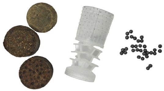
EUNDERSTANDING BALLISTICS: A PRIMER FOR COURTS 19 Wads (Figure 17) Wads are internal components of shotgun cartridges. Their purpose is to seal the gases produced by the burning propellant in the barrel of the shotgun and to protect the shot. They can be made from various substances, including plastic, fibre, cardboard and combinations thereof. Some plastic wads include a cup-shaped section to hold the shot pellets; this is made up of a number of petals or fingers. Conventional shotgun cartridges can contain different quantities of shot depending upon the use for which they are intended. For example, a 12-gauge cartridge will normally contain between 21 and 42 grams (g) of shot, with between 27 g and 36 g being most common. FIGURE 17 Fibre wadding, a plastic wad and lead shot. Shot pellet sizes Shot pellets for use with shotgun cartridges are graded according to size. In the UK, the larger the number, the smaller the size of the shot pellets. For example, a number 1 size shot will be approximately 3.6 mm diameter, whereas a number 5 will be approximately 2.8 mm diameter. Numbers 5, 6 and 7 size shot are commonly used for hunting small game and for clay pigeon shooting; because of their availability, they are also frequently used in crime.
20                                                             UNDERSTANDING BALLISTICS: A PRIMER FOR COURTS

Blank and tear gas cartridge construction (Figures 18 and 19)
Modern blank cartridges for self-loading pistols are similar in design to bulleted
cartridges with the exception that they lack a projectile. Most have a (green) coloured
plastic closure at the case-mouth. The front of the cartridge case is rolled over the
plastic closure to hold it in place.

 FIGURE 18

The components of a blank cartridge.

           Primer                                                                         Plastic closure

Illustration created by Christopher Poole, National Ballistics Intelligence Service (NABIS).

Tear gas cartridges are essentially identical with the exception that they contain a
small amount of tear gas material in the form of a finely divided crystalline solid. Such
cartridges have coloured plastic closures, the colour indicating the type of tear gas
chemical present. Weapons designed to fire blanks and irritant gas cartridges are
sold freely in continental Europe and are often referred to as gas/alarm pistols. The
pistol discharges the irritant tear gas a short distance from the muzzle, theoretically
deterring an attacker. In the UK they are prohibited weapons and are easily capable of
conversion to discharge a missile. Certain types of UK blank-firing weapons, incapable
of conversion or discharging tear gas, are not prohibited by statute.
UNDERSTANDING BALLISTICS: A PRIMER FOR COURTS 21 FIGURE 19 Blank and tear gas cartridges often show coloured plastic closures, typically green (blank) and red (tear gas). Tear gas-firing (or gas/alarm) self-loading pistol operation Normally, tear gas-firing self-loading pistols operate in an identical way to normal self-loading pistols, except no projectile (only tear gas) is expelled from the barrel. In addition, many of these pistols have a threaded muzzle to enable them to be fitted with a flare launcher, the flare being launched by using a standard blank cartridge. 1.3 Calibre True calibre is a measure of the internal bore of a weapon. However, in common usage, calibre refers to the type of cartridge a gun is designed to fire. An example of a common pistol calibre is the 9 mm Parabellum, the most common pistol calibre in the world. Confusingly, there are often several different designations for the same calibre, and so 9 mm Parabellum is also called 9 mm Luger, 9 mm P, 9 mm NATO or 9 x 9 mm. In addition, there are other 9 mm calibres such as 9 mm Makarov and 9 mm Short. These cannot be discharged in a 9 mm Parabellum pistol nor are they compatible with one another. For this reason, forensic scientists should always be specific in their statements and will normally comment on the compatibility between any weapon and ammunition examined. Calibres with metric dimensions are usually European in origin whereas those with imperial dimensions are usually North American or British in origin. Obsolete calibres are calibres for which ammunition is no longer commercially available, and weapons chambered in these calibres are often regarded as antiques under UK law.
22                                                  UNDERSTANDING BALLISTICS: A PRIMER FOR COURTS

1.4 Internal ballistics
The subject of internal ballistics covers the time from when the primer is struck until the
projectile exits the barrel.

When the trigger is pulled, the firing pin will strike the primer at the base of the cartridge.
This causes a shower of sparks to ignite the propellant powder in the cartridge case.
The propellant powder burns at a very high rate, creating a large volume of gas and a
substantial increase in pressure. The pressure is contained by the breech block at the
rear of the cartridge and the barrel surrounding the cartridge, so that the pressure will
act on the projectile (or the wad in a shotgun), driving it down the barrel.

The rate at which the propellant burns is calculated to ensure that the pressure
continues to rise so that the projectile travels down the barrel. One might expect,
therefore, that the powder in a pistol cartridge would burn more rapidly than the
powder in a rifle cartridge, the slower burning of the rifle cartridge ensuring constant
acceleration of the projectile down the longer barrel. This is the case, and also explains
why the same projectile fired from the same cartridge but from a weapon with a shorter
barrel will produce a lower velocity than from a long barrel. Similarly, projectiles from a
‘sawn-off’ shotgun or rifle will produce lower velocities.

1.5 External ballistics
The subject of external ballistics deals with the behaviour of the projectile after its exit
from the barrel, during its flight and then when it makes contact with a target – this is the
trajectory. Many factors combine to influence the trajectory of the projectile.

When in flight, the main forces acting on the projectile are gravity and air resistance (which
can take the form of both drag and wind deflection). When looking at small arms external
ballistics, gravity imparts a downward acceleration on the projectile, causing it to drop from
the line of sight. Drag or air resistance decelerates the projectile with a force proportional
to the square of the velocity. Wind makes the projectile deviate from its trajectory.

As a result of gravity, a projectile will follow a parabolic trajectory. To ensure that the
projectile has an impact on a distant target, the barrel must be inclined to a positive
elevation relative to the target line. This is known as sighting the weapon and explains
why a weapon has to be sighted at different ranges. To give a practical example, a
projectile fired from a rifle sighted to hit a target at 150 metres might also strike the point
of aim at 50 metres but will shoot high at 100 metres and low at 200 metres (Figure 20).
UNDERSTANDING BALLISTICS: A PRIMER FOR COURTS                                                                   23

 FIGURE 20

A. 	An unsighted rifle will miss the aim point at 150 metres owing to the effects of gravity
     and deceleration on the projectile’s trajectory.
B.	A sighted rifle will compensate for these effects with a parabolic trajectory and hit
    the aim point at the 150 metre mark.

A                                                                                               Distance
                                                                                                Line of sight

                                                                                                Bullet trajectory
       50 metres                  100 metres                 150 metres                  200 metres

B                                                                                               Distance
                                                                                                Line of sight

                                                                                                Bullet trajectory

       50 metres                  100 metres                 150 metres                  200 metres

Illustration created by Christopher Poole, National Ballistics Intelligence Service (NABIS).

Projectiles discharged from a rifled barrel are spin-stabilised. This is the spin created
by rifling as the projectile passes through the barrel. The spin gives the projectile
gyroscopic stability, preventing it from tumbling in flight. Without this spin being imparted
to the projectile, it quickly becomes unstable and accurate shooting is impossible.

Ballistic tables predict the path of a bullet by considering the many external factors
above. If the ballistic coefficient (BC) of a projectile is known – it combines the air
resistance of the bullet shape (the drag coefficient) and its sectional density (a function
of mass and bullet diameter) - all parameters relating to ballistic flight can be calculated.
These are sometimes used by forensic scientists to determine, for example, the
maximum distance a projectile fired from a particular weapon could travel. It should be
noted, however, that use of this type of information is rare, as most criminal shootings
take place at very close range, rarely exceeding a few metres.
24 UNDERSTANDING BALLISTICS: A PRIMER FOR COURTS 1.6 Terminal ballistics Terminal ballistics includes the study of wound ballistics, and generally relates to the behaviour and effects of a projectile when it has an impact on a target and transfers its energy thereto. Bullet design and the velocity of impact largely determine how effective the contact is. ‘Terminal ballistics’ covers the impact of any projectile striking any target, but often concentrates on the effects of small arms ammunition on a live target, human or animal, and the ability of the projectile to incapacitate or kill. Significant factors are bullet weight, composition, velocity and shape. Projectiles are designed either for maximum accuracy or for penetration of a target while avoiding over-penetration. They thus cause maximum damage to the intended target, but minimise the risk of peripheral unintended damage. Frangible bullets are designed to disintegrate when they impact a target, particularly a hard target. This reduces the risk of over-penetration and contact with unintended targets. They are often used for training or for law enforcement in densely populated areas. Expanding bullets, such as hollow-point or soft-point bullets, are designed to expand or fragment shortly after impact. This causes a rapid transfer of the bullet’s energy, thereby increasing tissue disruption, speeding incapacitation and increasing the likelihood of death. It also reduces the chance of over-penetration (where the projectile leaves the intended target and may accidentally make contact with a secondary target). Armour-piercing bullets are designed to defeat hard targets; they will have a mild steel or hardened steel core and will be designed to stay intact on impact to aid penetration power. Hard targets include body armour and armour used to protect vehicles.
UNDERSTANDING BALLISTICS: A PRIMER FOR COURTS                                                25

2. Scene interpretation
The assessment and interpretation of a firearms crime/discharge scene is a very
important part of the role of a firearms forensic scientist. Here we can determine a
number of factors, including:

1. number of weapons/type of weapon/firearm utilised

2. number of discharges

3. position of shooter or firing point

4. angle of discharge

5. range of fire.

It is important from a police investigative perspective that the scientist can provide this
type of information as quickly as possible. The recording and recovery of any ballistic
item is of extreme importance. First, it can provide an accurate interpretation of the
crime scene, a major benefit for expert evidence testimony in a court of law; second, if
the ballistic items are recovered in a controlled manner, there is then maximum potential
for evidence recovery from them later in the examination process at the forensic
laboratory. This evidence can be DNA or fingerprints (or both), for example. It certainly is
a major benefit if those at the scene of a shooting are highly experienced in the field of
forensic firearms/ballistics, as this ensures an accurate interpretation and effective and
efficient recovery of potential exhibits.

2.1 Ricochet
This is not a common occurrence in criminal shootings, but the firearms expert will assess
the scene for yielding, semi-yielding or non-yielding surfaces, if it is suspected that the
projectile has not followed a normal trajectory. In such cases, the bullet/projectile is likely
to bear specific damage due to the effects of having ricocheted off a particular surface.

•   A yielding surface could be sand or some types of soft wood.

•   A semi-yielding surface could include some types of metal or harder wood.

•   A non-yielding surface could be steel or other hard metal.

A major factor is the elasticity of a surface. The expert will determine how this might
cause a bullet/projectile to act after striking such a surface.
26                                               UNDERSTANDING BALLISTICS: A PRIMER FOR COURTS

2.2 Trajectory
Determining the trajectory of a bullet will help the scientist form a conclusion as to
the location from where the shot was discharged. This can be done with the use of
modern equipment such as lasers, but traditional methods, such as inserting steel
rods through entry/exit holes, are still used, particularly in post-mortem examinations
of victims of shooting.

2.3 Damage and range interpretation
An examination of the damage caused can often lead to a determination of the type
of bullet, calibre, etc. It can also be used to look at the range at which a shot has
been discharged, particularly when shotguns are used. This is because the pattern
of the shot will increase with range. Typically, the shot pattern spreads approximately
2.5 cm for every metre it travels from the muzzle, but this will vary with different guns
and cartridges. It is a popular myth that a sawn-off shotgun produces greatly enlarged
patterns at any given range; in reality, the patterns produced from most sawn-off
shotguns are little different from those produced from full-length weapons.

Research has recently been published that evaluates the effect of barrel length on pellet
distribution patterns of sawn-off shotguns (Maitre et al. 2021). The research concluded
that there is a noticeable increase in pellet distribution area between the unaltered
shotgun and altered barrel lengths of all shotguns, however, distance from the target
as well as the presence of a choke in the shotgun’s barrel was found to have a greater
impact on the pellet distribution.

2.4 Wound interpretation
This aspect is generally considered by a forensic pathologist. Nevertheless, ideally, a
forensic pathologist working in conjunction with the firearms expert will be more likely
to produce an accurate and reliable interpretation. Unfortunately, many myths surround
how entry and exit wounds are differentiated, an example being that exit wounds are
always larger than entry wounds. In fact, many factors affect the size and morphology of
these wounds and it is only with considerable experience that an expert can determine
entry and exit wounds, bullet calibre, distance determination and direction of fire.
UNDERSTANDING BALLISTICS: A PRIMER FOR COURTS                                              27

3. Microscopy
3.1 Introduction
Microscopic tool markings found on fired ballistic material, such as cartridge cases and
bullets, are examined using a comparison microscope. This particular technique of
examining ballistic tool markings is generically referred to as ‘microscopy’, and forms part
of established forensic science practice used by ballistics examiners around the world.

The foundation principles of microscopy used by ballistics examiners were formally
established in 1969 by the Association of Firearm and Tool Mark Examiners (AFTE),
based in the USA. AFTE’s ‘theory of identification’ underpins the basis of microscopy
as it is applied by ballistics examiners and comprises three main principles:

1. An expert ballistics examiner may form the opinion that two ballistic samples match
   if there is ‘sufficient agreement’ of microscopic tool markings.

2. That ‘sufficient agreement’ is related to the significant duplication of random tool
   markings. These random tool markings contain ‘individual characteristics’ in the
   form of peaks, ridges and furrows within surface contour markings. A match is
   established when sufficient corresponding ‘individual characteristics’ markings are
   found between two sample sets. Agreement is considered sufficient when it exceeds
   the best known ‘non-match’ of markings known to the expert examiner that originate
   from different tools; therefore, making the likelihood of a different tool having been
   used a ‘practical impossibility’.

3. That ‘sufficient agreement’ of tool markings is subjective and the interpretation is
   based only on an examiner’s training and experience.
28                                               UNDERSTANDING BALLISTICS: A PRIMER FOR COURTS

In addition to this, expert ballistics examiners also generally use the following range
of conclusions upon completing a microscopic comparison:

•    Conclusive – the items were marked by the same weapon.

•    There were indications that the samples were marked by the same weapon, but
     there is insufficient detail present to determine conclusively.

•    The comparison was inconclusive; it was not possible to determine whether the
     items had been marked by the same weapon.

•    There were indications that the samples had been marked by different weapons,
     but there is insufficient detail present to make a conclusive determination.

•    Elimination – the items were marked by different weapons.

It should be made clear that there has been much criticism in recent years of the
basis on which ballistics experts reach their conclusions, in particular the definition of
‘sufficient agreement’ and the assertion of a ‘practical impossibility’ based only on the
examiner’s training and experience. Much of the criticism has been in the USA and has
focused on a lack of peer-reviewed scientific papers relating to the subject, as well as
an absence of error rates in such a subjective analysis.

In the UK, all significant conclusions drawn must be peer reviewed by at least one
additional expert examiner. The peer review process must be conducted independently
and objectively to ensure a non-biased result. If different conclusions are reached by expert
examiners, or there are differing levels of agreement between expert examiners, this will
be disclosed to the court via the evidential statement provided by the expert examiner.

All forensic science providers in the UK who are presenting firearms and firearms discharge
residue evidence in court should be accredited to the International Standard ISO 17025-
2017. As part of achieving this standard, the forensic science providers would have to
satisfy the United Kingdom Accreditation Service, the UK’s national accreditation body, that
their microscopic examinations are part of a scientifically valid process. This would include

•    the production of error rates associated with the conclusions derived from the
     comparison of ballistic material

•    evidence to support the assertion that certain markings produced by firearms on
     bullets and cartridge cases could be attributed to an individual firearm.
UNDERSTANDING BALLISTICS: A PRIMER FOR COURTS 29 Error rates in microscopy at the National Ballistics Intelligence Service (NABIS) and NABIS-affiliated laboratories are determined from over 10 years of competency testing of ballistics experts. This has involved more than 700 blind competency tests with around 1,000 potential links. The error rate for false negatives (links not identified) is 2.1% and the error rate for false positives (links identified that are not links) is 0.7%. The latter figure is of most concern. With the independent peer review system, the error rate for false positives falls to approximately 0.005% or one in 20,000. Scientific research to objectively underpin the assertion that a particular bullet or cartridge case could be attributed to an individual firearm is also slowly progressing. 3.2 Identification of weapons When a firearm is discharged, marks are left on cartridge cases and bullets. These have been produced by parts of the firearm as it has come into contact with the surface of the cartridge case or bullet. Ballistic materials such as fired cartridge cases and bullets are recovered from a crime scene and submitted to a forensic firearms laboratory (Figure 21) . The firearms examiner will view the marks on the fired items under a comparison microscope. FIGURE 21 Fired ballistic material commonly recovered from crime scenes.
30                                                 UNDERSTANDING BALLISTICS: A PRIMER FOR COURTS

Examination of certain marks on fired cartridge cases and bullets recovered from a
crime can initially aid the identification of the type of weapon from which the ammunition
was fired. These marks might be

1. class characteristics: a series of ‘family’ resemblances which might be present in
   weapons of the same make and model; these marks are a result of design factors
   of the gun

2. sub class characteristics: where the features introduced during the manufacturing
   process can change over time and usage

3. unique characteristics: randomly occurring features created at the time of
   manufacture and during use and abuse of the tool.

Cartridge Cases
The primary marks left on the fired cartridge case are made by the firing pin, the breech
face of the gun, the ejector and the extractor.

Bullets
The marks on the fired bullet are made by the rifling on the inside of the barrel. The
rifling marks will be either a left (L) or right (R) twist and consist of the number of lands/
grooves, eg 6L, 4R. The width of the lands (the raised portions between the grooves
inside the barrel after the spiral grooves are cut to produce the rifling) and grooves can
also be taken into account to contribute to identification of make and model.

The Forensic Science Regulator for England and Wales issued guidance in February
2021 on the development of evaluative opinions across a range of forensic evidence
types including firearms discharge examination and analysis/firearms examination. This
new standard must be complied with by 2026 and will mean that the expression of
opinions relating to these examinations will follow a likelihood ratio approach.
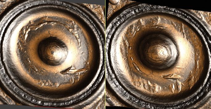
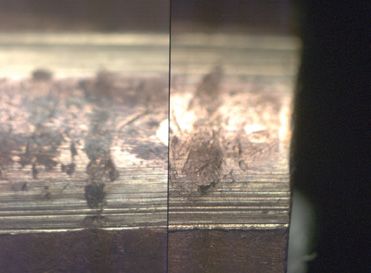
UNDERSTANDING BALLISTICS: A PRIMER FOR COURTS                                                31

3.3 Comparison of fired items (Figures 22 and 23)

 FIGURE 22                                        FIGURE 23

Microscopic comparision of two fired             Microscopic comparision of two fired
cartridge cases showing impressed                bullets showing striated rifling detail.
firing-pin and breech-face markings.

Under a comparison microscope, further examination can reveal fine detail present on
the cartridge cases and bullets. These marks are known as individual characteristics,
which are reproducible and unique to the gun which produced them. They are
produced by random imperfections or irregularities of a tool’s surface.

Individual characteristics are often present within the firing-pin impression, the breech-face
marks, ejector mark, etc on cartridge cases and within the rifling marks on bullets. If the
bullet were fired in a barrel with no rifling (smooth bore), individual characteristics might
also be present on the marks left on the bullet from the internal surface of the barrel.

It is these individual characteristics which allow forensic firearms examiners to form an
opinion that items were fired from the same gun.

For instance, a fired cartridge case from incident A can be compared with a fired
cartridge case from incident B. The examiner will examine both items together under a
comparison microscope for similarity in striations etc. If sufficient fine detail is present in
agreement, the examiner will be able to state that both cartridge cases were fired by the
same gun. This implies that the same gun was used in both incidents.
32                                                UNDERSTANDING BALLISTICS: A PRIMER FOR COURTS

3.4 Linking ballistic material to a recovered weapon
When a firearm is recovered, it can be submitted to a forensic firearms laboratory and
test fired. Using a comparison microscope, the test-fired cartridge cases and bullets can
be compared with fired items recovered from outstanding crimes. The examiner can
form an opinion as to whether the items were fired by the same gun. If sufficient fine
detail is present, the examiner can state that a fired item was fired by the recovered gun.

3.5 The Integrated Ballistics Identification System (IBIS) (Figure 24)
Ballistics examiners often use an electronic automated searching system called IBIS
(Integrated Ballistic Identification System), which allows ‘virtual’ analysis of ballistic
samples held across different laboratories. It is a database of digital images which can
be searched using correlation software. The software will rank potential matches for the
expert to review on screen and offers quick time analysis. Within the UK, IBIS is installed
at laboratories in London, Manchester, Birmingham, Glasgow and Belfast, providing
complete national coverage.

IBIS comprises three main components:

•     rassTRAX HD3D acquisition unit
     B
     This unit allows the examiner to load physical samples of fired cartridge cases. The
     unit captures high-definition three-dimensional (HD3D) digital images of the firing-pin
     impressions, ejector markings and headstamp details on fired cartridge cases.

•     ulletTRAX HD3D acquisition unit
     B
     This unit allows the examiner to load physical samples of fired bullets. The unit
     captures HD3D digital images of the rifling impressions on fired bullets.

•    MatchPoint Plus analysis station
     This station allows the examiner to review images of potential matches. Advanced
     computer software provides an accurate correlation list of potential matches, ranked
     in order of probability, and a ‘virtual microscope’ to view ballistic image comparisons.
UNDERSTANDING BALLISTICS: A PRIMER FOR COURTS 33 Once physical ballistic samples have been loaded onto the BrassTRAX and/or BulletTRAX acquisition units, the captured digital images are submitted to a correlation server, where they are automatically analysed using mathematical algorithms which return results to the MatchPoint analysis station. The expert ballistic examiner will review all relevant images on screen to determine whether there is any link. All potential matches highlighted by IBIS are further manually checked on a traditional comparison microscope. It is also worthy of note that the UK-based IBIS has the facility to search against servers of other IBIS member countries, offering an international searching ability to ballistics examiners. FIGURE 24 IBIS HD3D imagery of two fired cartridge cases.
34 UNDERSTANDING BALLISTICS: A PRIMER FOR COURTS
4. Mechanical condition
A suspect firearm can be examined to determine whether it is in normal working order
and/or could be discharged accidentally. The expression ‘accidental discharge’ could
mean the gun has been fired as a result of:
1. an inappropriately low trigger pull
2. the failure of a safety device
3. an unintentional discharge due either to pressure inadvertently applied to
the trigger or
4. some other failure of the gun owing to poor condition.
4.1 Trigger pressures
There are two general types of firearm mechanism or ‘lock’:
• a hammer which rotates round an axis, for example the external hammer in a
revolver or the internal tumbler in a shotgun
• a striker or bolt which moves longitudinally, for example the striker in a pistol, the
cocking knob in a bolt-action rifle or the bolt in a sub-machine gun.
In each case, the hammer or striker/bolt is powered by a spring and is held in the
cocked position by an internal component called the sear. The sear engages either in
a notch called the bent or sometimes, in the case of a striker, behind a protruding lug.
The trigger is a lever which lifts the sear out of engagement with the bent allowing the
hammer or striker/bolt to be driven forward under spring tension and to detonate the
cartridge primer via the firing pin.
There are many variations on this general principle, but all rely on the sear being
dragged out of engagement from the bent, ie on the separation by motion of two
interacting metal surfaces. The science of interacting surfaces in relative motion,
including the study of friction, lubrication and wear, is known as tribology.
Trigger pull is the force applied to the trigger to cause sear release. Trigger pull is
traditionally described in units of weight (pounds or kilograms) and measured by
hanging calibrated weights on the trigger to determine whether a given weight will fire
the gun or whether the hammer will remain held by the sear. Spring gauges or digital
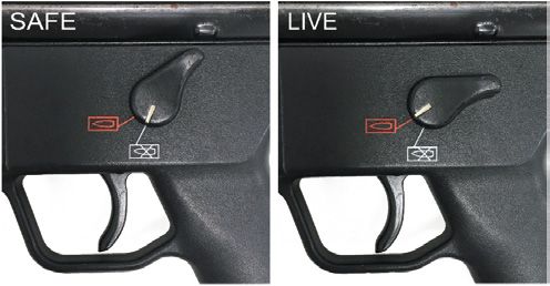
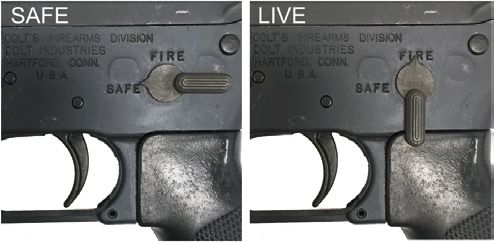
force gauges can give a crude indication of trigger pull.UNDERSTANDING BALLISTICS: A PRIMER FOR COURTS 35 The most significant factor affecting trigger pull is the spring pressure on the hammer or striker/bolt. Some sears might also be under tension from a sear spring. Other factors relate to the engagement of the sear with the bent, ie the shape and profile of both sear and bent, the surface area of contact and the friction from rough or polished surfaces. Variable factors include the presence of rust, dirt or oil and surface temperature. Consideration might be given to the angle at which the gun is held. In normal use, the operator’s finger will tend to apply pressure to the trigger in a direction slightly upward relative to the longitudinal axis of the gun, while the very minimum weight necessary to fire the weapon might be achieved at the tip of a curved trigger applied in some other direction. Clearly, there is much variation here depending on weapon type and design. The trigger pull might be assessed as normal for that particular type of firearm, or dangerously light or excessively heavy. For example, a sporting shotgun will have a normal trigger pull of 3½ to 5lb, a military rifle 6 to 8lb, etc. The trigger pull of a suspect weapon might be compared with others of the same make held in a reference collection, or with values collated in databases or published sources. There is a subjective element to interpreting whether a trigger pull might be regarded as normal. For example, a relatively light trigger pull might be acceptable on a controlled firing range but not in the field. A trigger pull of less than 1lb is dangerously light. 4.2 Safety devices, external and internal (Figure 25) Many weapons are fitted with an external safety catch. The exceptions include shotguns with external hammers, almost all revolvers and many cheap air weapons. Most safety catches are applied manually at some stage during the normal loading and firing procedure, but some weapons, including certain shotguns and air rifles, have an automatic safety which sets when the barrels are opened. The location of a safety catch will depend on the type of gun. Typical examples include on the frame or slide of a self- loading pistol, behind the opening lever of a shotgun, on the receiver or bolt of a rifle or incorporated within, or close to, a trigger guard. There is much variation. The position of a safety catch might, depending on design, be indicated visually by a letter S for ‘safe’ or ‘on’ and F for ‘fire’ or ‘off’, or by a red dot or band obscured when the safety catch is in the ‘safe’ position but revealed in ‘fire’ position. There is much variation, but the safety catch will be positioned so that it can be readily moved to ‘off’ by the operator’s thumb.
36                                              UNDERSTANDING BALLISTICS: A PRIMER FOR COURTS

Most safety catches are connected to a mechanism which physically blocks movement
of the trigger, thereby preventing discharge. For a given suspect weapon, the normal
operation of the safety catch can be tested and the condition of its components assessed.

Certain types of firearm might have internal safety features designed to prevent the gun
from discharging except by pressing the trigger. These include, but are not limited to, a
rebound safety, a transfer bar, a disconnector and a firing-pin safety. In general, these
passive safety mechanisms prevent a gun discharging if it is dropped to the ground
or if the normal loading and firing procedure is not followed. There is much variation
depending upon weapon type and even make and model.

 FIGURE 25

Two examples of safety catches, one with symbols and the other with text to identify
‘safe’ and ‘fire’ positions.
UNDERSTANDING BALLISTICS: A PRIMER FOR COURTS                                               37

4.3 Unintentional discharge
‘Unintentional discharge’ is generally taken to mean:

1. owing to a faulty trigger mechanism or safety device or a broken, worn or missing part,
   the gun has been discharged other than by pressing the trigger in the normal manner

2. pressure was applied to the trigger by some means other than the operator pressing
   the trigger in the normal manner (perhaps caught up in clothing or struck by some
   other object)

3. the trigger was pressed by the operator but not deliberately or consciously (perhaps
   in the heat of the moment or by surprise).

A suspect weapon can, in light of one of the above allegations, be subjected to drop
tests and jarring tests. Drop (or ‘bumping’) tests involve dropping the gun under controlled
conditions onto known surfaces in various orientations and from various heights. Such
tests can demonstrate whether the sear is released from the bent without the trigger
being pressed or whether the firing pin is driven onto the cartridge primer as a result of
inertia. Jarring tests involve striking the gun at various points and in various directions.

In general, a gun with a light trigger pull is more susceptible to sear release due to
bumping or jarring. Drop tests and jarring tests are best designed to reproduce the
effects of any scenario proposed by the prosecution or defence. A different approach
might be taken if the allegation is of a shot fired during a struggle compared with, say,
the gun being dropped to the ground. Care will be taken since drop and jarring tests
have the potential to change irreparably the mechanical condition of the gun.
You can also read