UNILINK SWING-AWAY THIGH SUPPORT UNILINK WEGSWENKBARE SEITLICHE PELOTTENHALTERUNG SUPPORT DE CUISSE PIVOTANT UNILINK SUPPORTO PER COSCIA ...
←
→
Page content transcription
If your browser does not render page correctly, please read the page content below

Pelvic Support (EN)
                                                  Beckenstütze (DE)
                                                Soutien pelvien (FR)
                                                Supporto pelvico (IT)
                                                 Soporte pélvico (ES)

UniLink Swing-Away Thigh Support
UniLink Wegswenkbare seitliche Pelottenhalterung
Support de cuisse pivotant UniLink
Supporto per coscia oscillante UniLink
Soporte de muslo abatible UniLink

             Owner’s Manual - Maintenance Guide
            Benutzerhandbuch - Wartungsanleitung
             Manuel d'utilisation - Guide d'entretien
            Manuale d'uso - Guida alla manutenzione
           Manual de usuario - Guía de mantenimiento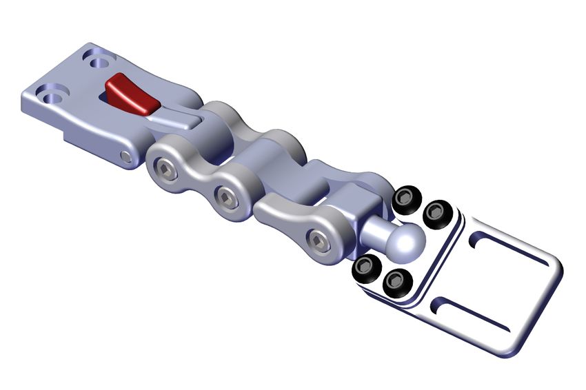
Table of Contents

Customer Satisfaction ..........................................................................i
     General ............................................................................................................... i
General Information ............................................................................ii
     Warranty ........................................................................................................... ii
     Supplier Reference........................................................................................ ii
Warning Labels....................................................................................iii
     Warning Labels..............................................................................................iii
            Limited Liability.............................................................................................iii
            Testing ..............................................................................................................iii
Design and Function ........................................................................ 1-2
      Intended Use...................................................................................................1
            Features.............................................................................................................1
            Operating Laterals ........................................................................................2
            Adjusting Adductors ....................................................................................2
Installation ........................................................................................ 3-6
       Standard Cane Mounting...........................................................................3
            Standard Track Mounting ..........................................................................4
            Pad Mount Installation................................................................................5
            Thigh Pad Installation..................................................................................5
            Full-Surface Contact Mount Installation ..............................................6
            Full-Surface Contact Mount Adjustment .............................................6
First Time Use .......................................................................................7
       Dealer Assistance ..........................................................................................7
       User Testing.....................................................................................................7
       Conditions of Use .........................................................................................7
Care and Maintenance.........................................................................8
       Safety .................................................................................................................8
       Cleaning............................................................................................................8
       Disposal.............................................................................................................8
1                                                                                                                              EN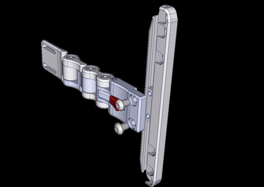
Customer Satisfaction
Stealth Products is committed to 100% customer satisfaction. Your complete satisfaction is
important to us. Please contact us with feedback or suggestions to help us improve the quality
and usability of our products.

You may reach us at:

                       Stealth Products, LLC
                    104 John Kelly Drive, Burnet, TX 78611

     Phone: (512) 715-9995                          Toll Free: (800) 965-9229
     Fax: (512) 715-9954                            Toll Free: (800) 806-1225
                             info@stealthproducts.com
                              www.stealthproducts.com

                                                                  UK Authorized Representative

 MDSS GmbH                        SODIMED SA                      MDSS-UK RP
 Schiffgraben 41                  Chemin Praz Devant 12           6 Wilmslow Road, Rusholme
 30175 Hannover                   1032 Romanel sur-Lausanne       Manchester M14 5TP
 Germany                          Switzerland                     United Kingdom

General
Read and understand all instructions prior to the use of the product. Failure to adhere to
instructions and warnings in this document may result in property damage, injury, or death.
Product misuse or failure to follow instructions will void the warranty.
Immediately discontinue use if any function is compromised, if parts are missing or loose, or if
any component shows signs of excessive wear. Consult with your supplier for repair,
adjustment, or replacement.
All persons responsible for fitting, adjustment, and daily use of the devices discussed in these
instructions must be familiar with and understand all safety aspects of the devices mentioned.
In order for our products to be used successfully, you must read and understand all instructions
and warnings, and maintain our products according to our instructions on care and
maintenance.
The installation instructions will guide you through this product’s options and possibilities.
Instructions are written with the expressed intent of use with standard configurations. They
also contain important safety and maintenance information, as well as describe possible
problems that can arise during use. For further assistance, or more advanced applications,
please contact Stealth Products at (512) 715-9995 or toll free at (800) 965-9229 or your
supplier.
Always keep the operating instructions in a safe place so they may be referenced as necessary.
All information, pictures, illustrations, and specifications are based on the product information
that was available at the time of printing. Pictures and illustrations shown in these instructions
are representative examples and are not intended to be exact depictions of the various parts
of the product.
EN                                                                                               i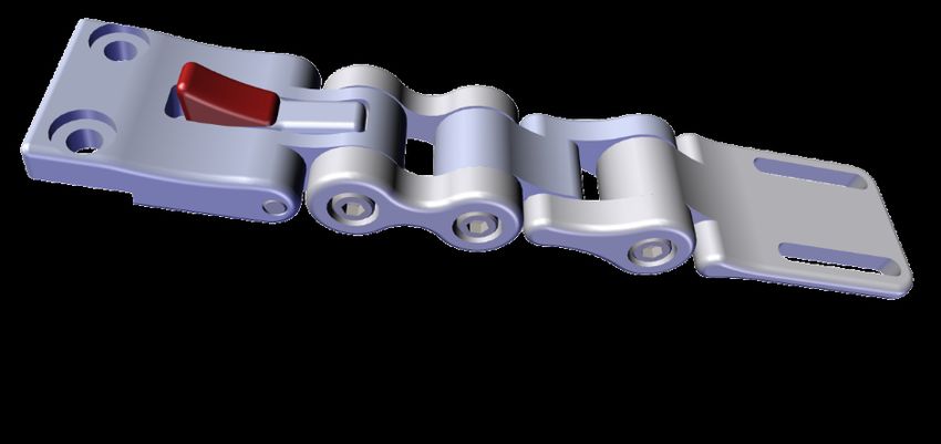
General Information

                                       CAUTION
     These products are designed to be fitted, applied, and installed exclusively by a
     healthcare professional trained for these purposes. The fitting, application, and
          installation by a non-qualified individual could result in serious injury.

Warranty
Our products are designed, manufactured, and produced to the highest of standards.
If any defect in material or workmanship is found, Stealth Products will repair or
replace the product at our discretion. Any implied warranty, including the implied
warranties of merchantability and fitness for a particular purpose, shall not extend
beyond the duration of this warranty. Stealth Products does not warrant damage due
to, but not limited to: Misuse, abuse, or misapplication of product, and/or modification
of product without written approval from Stealth Products, LLC. Any alteration or lack
of serial number, where applicable, will automatically void all warranty.
Stealth Products, LLC Is liable for replacement parts only. Stealth Products, LLC is
not liable for any incurred labor costs.
Stealth Products warrants against failure due to defective materials or workmanship:

                                     Covers: 2 years
                                   Hardware: 5 years
                                   Electronics: 3 years

In the event of a product failure covered by our warranty, please follow the
procedures outlined below:
Call Stealth Products at (512) 715-9995 or toll free at (800) 965-9229.
Request a Return Authorization (RA) form from the Returns Department and follow
the documentation instructions.

You can download additional copies of this manual by accessing the Stealth website
(www.stlpro.site/stealth-docs) and searching “UniLink Thigh Support” in the search
bar at the top of the page.

      Supplier Reference
      Supplier:
      Telephone:
      Address:

      Purchase Date:
      Model:

ii                                                                                   EN
Warning Labels

Warning Labels
Warnings are included for the safety of the user, client, operator, and property. Please
read and understand what the signal words DANGER, WARNING, CAUTION,
NOTICE, and SAFETY mean, and how they could affect the user, those around the
user, and property.

                                         DANGER
               Identifies an imminent situation which, if not avoided,
              may result in severe injury, death, and property damage.

                                        WARNING
                Identifies a potential situation which, if not avoided,
              may result in severe injury, death, and property damage.

                                        CAUTION

                Identifies a potential situation which, if not avoided,
           may result in minor to moderate injury and property damage.

                                       NOTICE

                Identifies important information not related to injury,
                            but possible property damage.

                                       SAFETY

         Indicates steps or instructions for safe practices, reminders of safe
         procedures, or important safety equipment that may be necessary.

Limited Liability
Stealth Products, LLC accepts no liability for personal injury or damage to property
that may arise from the failure of the user or other persons to follow the
recommendations, warnings, and instructions in this manual.
Stealth Products does not hold responsibility for final integration of final assembly of
product to end user. Stealth Products is not liable for user death or injury.

Testing
Initial setup and driving should be done in an open area free of obstacles until the
user is fully capable of driving safely.

EN                                                                                    iii
Design and Function

Intended Use
Lateral Stability is essential to balancing the body in relation to gravity. The long-
term goals of improved posture are to provide pressure relief, minimize orthopedic
consequences, normalize muscle tone, reduce active muscle requirements, and
increase the overall function of the user.

UniLink™ Thigh Support Solutions are highly adjustable lateral supports that
increase a user's stability and balance while in the chair, serve as tactile reminders of
positioning, and correct lateral thigh flexion. They provide a precise, durable means
of maintaining the user in a functional position, preventing further postural decay,
and diminishing the need for repetitive positioning of the user throughout their day.
Swing-away thigh supports flip down out of the way, but remain attached to the
chair, reducing the chances of them being misplaced, left behind, or lost.

                                                      •      Pads available in various
Features                                                     sizes to provide the
                                                             exact support required.

                                                                         •    Available
                                                                              Coolcore
                                                                              covers on the
                                                                              pads help to
                                                                              reduce heat
                                                                              buildup.

      •   Available full-surface
          pad mount provides
          extra degrees of                            •      Three points of lateral
          adjustability.                                     adjustment provide
                                                             exceptional positioning
                                                             of the support pad.

          •    Quick release latch
               facilitates easier transfers
               to and from the chair.             •       Various mounting
                                                          options provide a
                                                          secure connection to
                                                          the seat tubes of the
                                                          chair.

1                                                                                         EN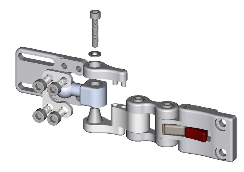
Design and Function

Operating Laterals
To operate the laterals:
1.        Depress the Quick Release button (A)             A

                                                                         134°

     2.     The lateral will swing free through 134° on
            either side of the initial locked position.
     3.     The lateral will only lock in place when
            returned to its initial position.

Adjusting Adductors
Standard laterals offer three points of adjustment:

     To adjust links (B):
     1.     Slightly loosen the M5 x 0.8 x
            25mm Socket Head Screws (B).
     2.     Set desired angles and tighten
            screws with a 4mm Hex
            Wrench.
     To adjust pad position:                           C
     1.     Slightly loosen the two M5 x
            0.8 x 10mm Socket Head
            Screws (C) and slide the pad to                          B
            the desired position.
     2.     Tighten screws to secure the
            pad in the new position. Do
            not over-tighten.

EN                                                                               2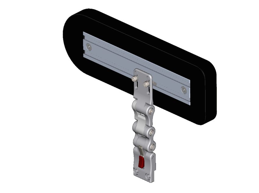
Installation

Standard Cane Mounting
To install and adjust standard cane mounting:

                                                  1.       Insert the M6 x 1.0 x
                                                           20mm Button Head
                                                           Screws (A) into the male
                                                           tube clamp (B) through
                                                           the counter-bored holes
                                                           and into the female side
                                                           of the tube clamp (C).

                                                                              D
                                                       C

             A
                              B
    2.   Attach the lateral by using M6 x
         1.0 x 12mm Button Head Screws
         (D) and mounting directly to the
         female side of the cane clamp.
         Tighten with a 4mm Hex Wrench.      3.   To adjust the lateral on the
                                                  cane, loosen the M6 x 1.0 x
                                                  20mm Button Head Screws
                                                  (A) and slide the clamp to
                                                  the desired position.

                                        WARNING
                    Installing the thigh guides incorrectly may cause
                   damage to the hardware and/or injury to the user.

3                                                                                     EN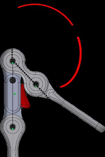
Installation
Standard Track Mounting
To install and adjust standard track mounting:

     1.   Insert the M6 x
          1.0 x 12mm
          Button Head
          Screws (A)
          through the
          counter-bored
          holes (B) and
          into the
          threaded holes
          of the Universal
          Track Nut (C).

                             A
                                                      2.   Set desired position
                                                           and tighten screws
                                                           with a 4mm Hex
                                                           Wrench.

                 B
                                       C
     3.   To adjust the lateral on the track, loosen the screws
          and slide it to the new position. Tighten the screws.

                                     CAUTION

          The use of improper tools may cause damage to the device.
      Inadequate tightening can cause components to become loose and
              cause discomfort for the user or premature failure.

EN                                                                                   4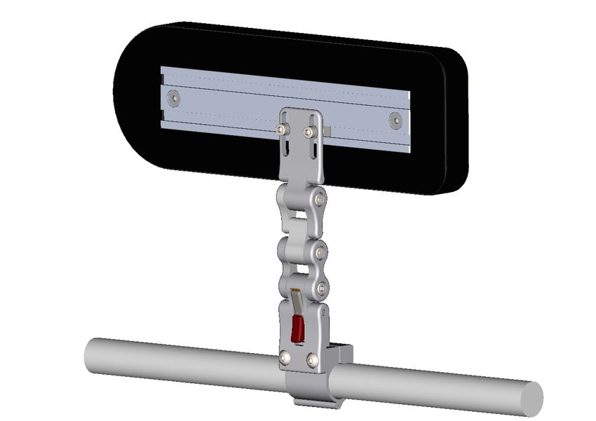
Installation

Pad Mount Installation

    1.    Place the conical socket of the Pad Mount (A)
          onto the conical mount of the 1.5" Link (B).
                                                       A                  C

           2.   Place the 1.5" Coupler        B
                (C) onto the 1.5" Link
                (B) as shown and
                secure it with an M5
                Flat Washer and M5 x
                0.8 x 25mm Socket
                Head Screw.

                                                           3.   Adjust the angle of
                                                                the Pad Mount and
                                                                tighten the M5 x
                                                                0.8 x 25mm Socket
                                                                Head Screw.

Thigh Pad Installation

     1.    Slide the Slab Nuts (A) into the
           desired location in the pad
           track.                                           A
     2.    Align the slots in the Pad
           Mount (B) with the threaded
           sleeves of the Slab Nuts (A)
     3.    Insert the M5 x 0.8 x 10mm
           Socket Head Screws into the            C
           threaded sleeves of the Slab
           Nuts (A).
     4.    Align the pad in the desired               B
           position and location and
           tighten the screws to secure it
           in place.

5                                                                                 EN
Installation
Full-Surface Contact Mount Installation*
1. Place the conical
socket of the 17mm D C
Ball Link of the
17mm Ball Link (A)
onto the conical
mount of the 1.5"
Link (B).
2. Place the 1.5"
Coupler (C) onto the
1.5" Link (B) as E
shown below and
secure it with an M5
Flat Washer and M5
x 0.8 x 25mm Socket A
Head Screw. B
* The Full-Surface Contact option will not fit UTS25100-L/R. The UTS2510F-L/R or UTS2530F-L/R must be used.
Full-Surface Contact Mount Adjustment
1. Loosen the M6 x 1.0 x 12mm
Button Head Screws (A) with a
4mm Hex Wrench.
A
2. Rotate and/or adjust the
angle of the pad to the
desired position.
3. Tighten the screws evenly.
CAUTION
Any connection must always be secured with all delivered screws.
Use only the screws provided in the package.
EN 6First Time Use
Dealer Assistance
During first-time use by the user, it is advised that the dealer or service technician not
only assembles the product, but also explains the configuration of user positioning
to the user (i.e., the user and/or the attendant). If needed, the dealer can make final
adjustments.
The UniLink Thigh Support Lateral should only
WARNING be prescribed and fitted by a qualified
health care professional.
User Testing
It is important that the customer is fully aware of the installation of the
UniLink Thigh Support Lateral, how to use it, and how it can be adjusted to
fit the client comfortably. As a dealer, proceed as follows:
• Explain and show the customer how you have executed the installation and explain the
function.
• Have the user test the position of the UniLink Thigh Support Lateral.
• Is the hardware in the proper position for the client?
• Can all controls be operated safely and with minimal effort?
• If needed, make any adjustments to the positioning.
• Explain possible problems to the customer and how to address them.
Conditions of Use
The UniLink Thigh Support Lateral is intended for use as installed by the dealer, in
accordance to the installation instructions in this manual.
Ensure the foreseen conditions of use are communicated by the dealer or service
technician to the user and/or attendant during the first-time use.
If usage conditions change significantly, please contact your dealer or a qualified
service technician to avoid unintended damage.
Failure to comply with these warnings
DANGER
could result in serious bodily harm.
7 ENCare and Maintenance
Safety
• Periodically check the hardware for loose screws or worn parts.
• Check the lateral pad for any foam breakdown and/or metal coming through
the foam. This could be potentially dangerous to the client.
SAFETY Repair or replace parts as needed.
CAUTION
Always check all mounting hardware, making sure each fastener
is properly tightened before using the lateral.
WARNING
Monitor the foam for breakdown and replace as needed.
Do not use thigh guide if foam is damaged or deteriorated.
Cleaning
• To wash the cover, remove the cover from the thigh guide.
• Machine wash the cover in cold water, delicate cycle, and drip dry.
• Do not allow the foam to get wet.
• Do not use the thigh guide without the cover in place.
DO NOT use bleach. DO NOT iron.
WARNING
Do not wash or dry in temperatures in excess of 176°F (80°C).
CAUTION
When removing the thigh guide, take care not to puncture,
tear, or otherwise damage the fabric or foam.
Disposal
For products that contain batteries or electronics, return the product to qualified
personnel for disposal. All components of the product should be disposed of
properly in accordance with respective local and national environmental regulations.
EN 8Inhaltsverzeichnis
Kundenzufriedenheit ............................................................................i
Allgemein .......................................................................................................... i
Allgemeine Informationen..................................................................ii
Garantie ............................................................................................................ ii
Lieferantenreferenz ...................................................................................... ii
Warnschilder........................................................................................iii
Warnschilder ..................................................................................................iii
Beschränkte Haftung ..................................................................................iii
Testen................................................................................................................iii
Design und Funktion ....................................................................... 1-2
Verwendungszweck......................................................................................1
Merkmale .........................................................................................................1
Bedienung der Laterals ...............................................................................2
Anpassen der Adduktoren.........................................................................2
Installation ........................................................................................ 3-6
Standardrohrmontage.................................................................................3
Standardschienenmontage .......................................................................4
Installation der Kissenhalterung..............................................................5
Installation des Oberschenkelkissens....................................................5
Vollflächige Kontaktmontage ...................................................................6
Anpassung der Vollflächenkontakthalterung.....................................6
Erstmalige Verwendung ......................................................................7
Händlerunterstützung .................................................................................7
Benutzertests ..................................................................................................7
Nutzungsbedingungen...............................................................................7
Pflege und Wartung ............................................................................8
Sicherheit..........................................................................................................8
Reinigung .........................................................................................................8
Verfügung ........................................................................................................8
1 DEKundenzufriedenheit
Stealth Products verpflichtet sich zu 100 % Kundenzufriedenheit. Ihre vollste Zufriedenheit ist uns
wichtig. Bitte kontaktieren Sie uns mit Feedback oder Vorschlägen, die uns helfen, die Qualität und
Benutzerfreundlichkeit unserer Produkte zu verbessern.
Sie erreichen uns unter:
Stealth Products, LLC
104 John Kelly Drive, Burnet, TX 78611
Telefon: (512) 715-9995 Zollfrei: (800) 965-9229
Fax: (512) 715-9954 Zollfrei Fax: (800) 806-1225
info@stealthproducts.com
www.stealthproducts.com
Bevollmächtigter Vertreter in
Großbritannien
MDSS GmbH SODIMED SA MDSS-UK RP
Schiffgraben 41 Chemin Praz Devant 12 6 Wilmslow Road, Rusholme
30175 Hannover 1032 Romanel sur-Lausanne Manchester M14 5TP
Germany Switzerland United Kingdom
Allgemein
Lesen und verstehen Sie alle Anweisungen vor der Verwendung des Produkts. Die Nichtbeachtung
der Anweisungen und Warnungen in diesem Dokument kann zu Sachschäden, Verletzungen oder
zum Tod führen. Der Missbrauch des Produkts oder die Nichtbeachtung der Anweisungen führt zum
Erlöschen der Garantie.
Stellen Sie die Verwendung sofort ein, wenn eine Funktion beeinträchtigt ist, wenn Teile fehlen oder
locker sind oder wenn eine Komponente Anzeichen von übermäßigem Verschleiß aufweist. Wenden
Sie sich bezüglich Reparatur, Einstellung oder Austausch an Ihren Lieferanten.
Alle Personen, die für die Montage, Einstellung und den täglichen Gebrauch der in dieser Anleitung
beschriebenen Geräte verantwortlich sind, müssen alle Sicherheitsaspekte der genannten Geräte
kennen und verstehen. Damit unsere Produkte erfolgreich verwendet werden können, müssen Sie
alle Anweisungen und Warnungen lesen und verstehen und unsere Produkte gemäß unseren Pflege-
und Wartungsanweisungen warten.
Die Installationsanleitung führt Sie durch die Optionen und Möglichkeiten dieses Produkts.
Anweisungen wurden mit der ausdrücklichen Absicht geschrieben, sie mit Standardkonfigurationen
zu verwenden. Sie enthalten auch wichtige Sicherheits- und Wartungsinformationen und
beschreiben mögliche Probleme, die während des Gebrauchs auftreten können. Für weitere
Unterstützung oder erweiterte Anwendungen wenden Sie sich bitte an Ihren Lieferanten oder an
Stealth Products unter (512) 715-9995 oder gebührenfrei unter (800) 965-9229.
Bewahren Sie die Bedienungsanleitung immer an einem sicheren Ort auf, damit Sie bei Bedarf
nachschlagen können.
Alle Informationen, Bilder, Illustrationen und Spezifikationen basieren auf den
Produktinformationen, die zum Zeitpunkt der Drucklegung verfügbar waren. Die in dieser Anleitung
gezeigten Bilder und Illustrationen sind repräsentative Beispiele und sollen keine genauen
Darstellungen der verschiedenen Teile des Produkts sein.
DE iAllgemeine Informationen
VORSICHT
Diese Produkte sind so konzipiert, dass sie ausschließlich von medizinischem
Fachpersonal angepasst, angewendet und installiert werden, das für diese Zwecke
ausgebildet wurde. Die Montage, Anwendung und Installation durch eine nicht
qualifizierte Person kann zu schweren Verletzungen führen.
Garantie
Unsere Produkte werden nach den höchsten Standards entworfen, hergestellt und
produziert. Wenn ein Material- oder Verarbeitungsfehler festgestellt wird, wird Stealth
Products das Produkt nach unserem Ermessen reparieren oder ersetzen. Jegliche
stillschweigende Garantie, einschließlich der stillschweigenden Garantien der
Marktgängigkeit und Eignung für einen bestimmten Zweck, erstreckt sich nicht über die
Dauer dieser Garantie hinaus. Stealth Products garantiert keine Schäden aufgrund von,
aber nicht beschränkt auf: Missbrauch, Missbrauch oder falsche Anwendung des Produkts
und/oder Modifikation des Produkts ohne schriftliche Genehmigung von Stealth Products,
LLC. Jegliche Änderung oder das Fehlen der Seriennummer führt gegebenenfalls
automatisch zum Erlöschen der Garantie.
Stealth Products, LLC haftet nur für Ersatzteile. Stealth Products, LLC haftet nicht für
anfallende Arbeitskosten.
Stealth Products garantiert gegen Ausfälle aufgrund von Material- oder
Verarbeitungsfehlern:
Bezüge: 2 Jahre
Hardware: 5 Jahre
Elektronik: 3 Jahre
Im Falle eines Produktfehlers, der von unserer Garantie abgedeckt wird, gehen Sie bitte
wie folgt vor:
Rufen Sie Stealth Products unter (512) 715-9995 oder gebührenfrei unter (800) 965-9229
an.
Fordern Sie ein Rücksendegenehmigungsformular (RA) bei der Rücksendeabteilung an
und befolgen Sie die Dokumentationsanweisungen.
Sie können zusätzliche Exemplare dieses Handbuchs herunterladen, indem Sie auf die
Stealth-Website (https://stlpro.site/stealth-docs) zugreifen und in der Suchleiste oben auf
der Seite nach „UniLink Thigh Support“ suchen.
Lieferantenreferenz
Lieferant:
Telefon:
Adresse:
Kaufdatum:
Modell:
ii DEWarnschilder
Warnschilder
Warnhinweise dienen der Sicherheit des Benutzers, des Kunden, des Bedieners und
des Eigentums. Bitte lesen und verstehen Sie, was die Signalwörter GEFAHR,
WARNUNG, VORSICHT, HINWEIS und SICHERHEIT bedeuten und wie sie sich auf
den Benutzer, die Umgebung des Benutzers und das Eigentum auswirken können.
Kennzeichnet eine unmittelbar bevorstehende Situation,
GEFAHR die, wenn sie nicht vermieden wird, zu schweren
Verletzungen, Tod und Sachschäden führen kann.
Kennzeichnet eine potenzielle Situation, die, wenn sie
WARNUNG nicht vermieden wird, kann zu schweren Verletzungen,
Tod und Sachschäden führen.
Kennzeichnet eine potenzielle Situation, die, wenn sie
VORSICHT nicht vermieden wird, zu leichten bis mittelschweren
Verletzungen und Sachschäden führen kann.
Kennzeichnet wichtige Informationen, die sich nicht auf
HINWEIS
Verletzungen beziehen, sondern auf mögliche Sachschäden.
Weist auf Schritte oder Anweisungen für sichere
Praktiken, Erinnerungen an sichere Verfahren
SICHERHEIT
oder wichtige Sicherheitsausrüstungen hin,
die möglicherweise erforderlich sind.
Beschränkte Haftung
Stealth Products, LLC übernimmt keine Haftung für Personen- oder Sachschäden, die
dadurch entstehen können, dass der Benutzer oder andere Personen die Empfehlungen,
Warnungen und Anweisungen in diesem Handbuch nicht befolgen.
Stealth Products übernimmt keine Verantwortung für die endgültige Integration der
Endmontage des Produkts für den Endbenutzer. Stealth Products haftet nicht für Tod
oder Verletzung des Benutzers.
Testen
Die Ersteinrichtung und das Fahren sollten in einem offenen Bereich ohne Hindernisse
erfolgen, bis der Benutzer in der Lage ist, sicher zu fahren.
DE iiiDesign und Funktion
Verwendungszweck
Seitliche Stabilität ist wesentlich, um den Körper in Bezug auf die Schwerkraft
auszugleichen. Die langfristigen Ziele einer verbesserten Körperhaltung sind
Druckentlastung, Minimierung orthopädischer Folgen, Normalisierung des Muskeltonus,
Verringerung der aktiven Muskelanforderungen und Steigerung der Gesamtfunktion des
Benutzers.
UniLink™ Thigh Support Solutions sind hochgradig einstellbare seitliche Stützen, die
die Stabilität und das Gleichgewicht eines Benutzers im Stuhl erhöhen, als taktile
Erinnerungen an die Positionierung dienen und die seitliche Oberschenkelbeugung
korrigieren. Sie bieten ein präzises, dauerhaftes Mittel, um den Benutzer in einer
funktionellen Position zu halten, einen weiteren Haltungsverlust zu verhindern und die
Notwendigkeit einer wiederholten Positionierung des Benutzers im Laufe des Tages zu
verringern. Schwenkbare Oberschenkelstützen klappen nach unten aus dem Weg, bleiben
aber am Stuhl befestigt, wodurch die Wahrscheinlichkeit verringert wird, dass sie verlegt,
zurückgelassen oder verloren werden.
• Polster in verschiedenen Größen
Merkmale erhältlich, um genau die erforderliche
Unterstützung zu bieten.
• Verfügbare Coolcore-
Überzüge auf den
Polstern helfen, die
Wärmeentwicklung zu
reduzieren.
• Die verfügbare
vollflächige Pad-
Halterung bietet • Drei seitliche
zusätzliche Justierpunkte sorgen
Einstellmöglichkeiten. für eine hervorragende
Positionierung des
Stützpolsters.
• Schnellverschluss
erleichtert den Transfer • Verschiedene Befestigungs-
zum und vom Stuhl. möglichkeiten sorgen für
eine sichere Verbindung mit
den Sitzrohren des Stuhls.
1 DEInstallation
Bedienung der Laterals
So bedienen Sie die Laterals:
1. Drücken Sie die Schnelllösetaste (A).
A
134°
2. Das Seitenteil schwingt frei um 134° auf beiden
Seiten der ursprünglichen verriegelten Position.
3. Das Seitenteil rastet nur ein, wenn es in seine
Ausgangsposition zurückgebracht wird.
Anpassen der Adduktoren
Standard-Seitenlatten bieten drei Einstellpunkte:
Anpassen der Verbindungen (B):
1. Lösen Sie leicht die M5 x 0,8 x 25
mm Innensechskantschrauben (B).
2. Stellen Sie die gewünschten Winkel
ein und ziehen Sie die Schrauben
mit einem 4mm Sechskantschlüssel
fest.
So passen Sie die Pad-Position an:
1. Lösen Sie leicht die beiden M5 x C
0,8 x 10mm
Innensechskantschrauben (C) und
schieben Sie das Polster in die
gewünschte Position. B
2. Ziehen Sie die Schrauben fest, um
das Pad in der neuen Position zu
sichern. Nicht überdrehen.
DE 2Installation
Standardrohrmontage
So installieren und justieren Sie die Standardrohrhalterung:
1. Stecken Sie die
Halbrundkopfschrauben
M6 x 1,0 x 20 mm (A) in die
Schellenhälfte Rohrklemme
(B) durch die angesenkten
Löcher und in die
Schellenhälfte Seite der
Rohrklemme (C).
D
C
A
B
2. Befestigen Sie das Seitenteil mit M6
x 1,0 x 12 mm Rundkopfschrauben
(D) und montieren Sie es direkt an
der weiblichen Seite der
Stockklemme. Mit einem 4mm
Sechskantschlüssel festziehen. 3. Lösen Sie zum Einstellen des
Seitenteils am Gehstock die M6 x
1,0 x 20 mm Rundkopfschrauben
(A) und schieben Sie die Klemme
in die gewünschte Position.
WARNUNG
Eine falsche Installation der Oberschenkelführungen kann zu
Schäden an der Hardware und/oder Verletzungen des Benutzers führen.
3 DEInstallation
Standardschienenmontage
So montieren und justieren Sie die Standard-Schienenmontage:
1. Stecken Sie die
Halbrundkopfschrauben
M6 x 1,0 x 12 mm (A)
durch die angesenkten
Löcher (B) und in die
Gewindelöcher der
Universal-
Schienenmutter (C).
A
2. Stellen Sie die
gewünschte Position ein
und ziehen Sie die
Schrauben mit einem
4mm Sechskantschlüssel
fest.
B
C
3. Um das Seitenteil auf der Schiene einzustellen, lösen Sie
die Schrauben und schieben Sie es in die neue Position.
Schrauben festziehen.
VORSICHT
Die Verwendung ungeeigneter Werkzeuge kann zu Schäden am Gerät führen.
Unzureichendes Anziehen kann dazu führen, dass sich Komponenten lösen und
Unbehagen für den Benutzer oder vorzeitiges Versagen verursachen.
DE 4Installation
Installation der Kissenhalterung
1. Platzieren Sie die konische Buchse der
Pad-Halterung (A) auf der konischen A C
Halterung des 1,5" Verbindungsstücks
(B).
B
2. Platzieren Sie den 1,5" Koppler (C)
wie abgebildet auf dem 1,5"
Verbindungsstück (B) und
befestigen Sie ihn mit einer M5-
Unterlegscheibe und einer M5 x 0,8
x 25mm Innensechskantschraube.
3. Passen Sie den Winkel
der Polsterhalterung an
und ziehen Sie die M5 x
0,8 x 25 mm
Innensechskantschraube
fest.
Installation des Oberschenkelkissens
1. Schieben Sie die Plattenmuttern
(A) an die gewünschte Stelle in
der Belagschiene.
2. Richten Sie die Schlitze in der
Pad-Halterung (B) mit den A
Gewindehülsen der
Plattenmuttern (A) aus.
3. Führen Sie die
Innensechskantschrauben M5 x
0,8 x 10 mm in die Gewindehülsen C
der Plattenmuttern (A) ein.
4. Richten Sie das Pad an der
gewünschten Position und Stelle B
aus und ziehen Sie die Schrauben
fest, um es zu befestigen.Richten
Sie das Pad an der gewünschten
Position und Stelle aus und ziehen
Sie die Schrauben fest, um es zu
befestigen.
5 DEInstallation
Vollflächige Kontaktmontage Installation*
1. 1. Setzen Sie die konische
Fassung des 17-mm- D C
Kugelgelenks des 17-
mm-Kugelgelenks (A) auf
die konische Halterung
des 1,5" Gelenks (B).
2. 2. Setzen Sie die 1,5"
Kupplung (C) wie unten
gezeigt auf das 1,5"
Verbindungsstück (B) und E
sichern Sie sie mit einer
M5-Unterlegscheibe und
einer M5 x 0,8 x 25-mm-
Innensechskantschraube. A
B
* Die Vollflächenkontakt-Option passt nicht zum UTS25100-L/R. Es muss der UTS2510F-L/R oder UTS2530F-L/R verwendet
werden.
Vollflächige Kontaktaufnahmeeinstellung
1. Lösen Sie die M6 x 1,0 x 12 mm
Rundkopfschrauben (A) mit einem
4mm Sechskantschlüssel.
A
2. Drehen und/oder justieren Sie
den Winkel des Pads in die
gewünschte Position.
3. Ziehen Sie die Schrauben
gleichmäßig an.
VORSICHT
Jede Verbindung muss immer mit allen mitgelieferten Schrauben gesichert
werden. Verwenden Sie nur die im Lieferumfang enthaltenen Schrauben.
DE 6First Time Use
Händlerunterstützung
Bei der erstmaligen Verwendung durch den Benutzer wird empfohlen, dass der Händler
oder Servicetechniker das Produkt nicht nur zusammenbaut, sondern dem Benutzer (d. h.
dem Benutzer und/oder der Begleitperson) auch die Konfiguration der
Benutzerpositionierung erklärt. Bei Bedarf kann der Händler letzte Anpassungen
vornehmen.
Die UniLink Thigh Support Lateral sollte nur von einem
WARNUNG Fachmann verschrieben und angebracht werden
Angestellter im Gesundheitswesen.
Benutzertests
Es ist wichtig, dass der Kunde vollständig über die Installation der seitlichen
UniLink Thigh Support Lateral informiert ist, wie sie verwendet wird und wie
sie bequem an den Kunden angepasst werden kann. Als Händler gehen Sie
wie folgt vor:
• Erklären und zeigen Sie dem Kunden, wie Sie die Installation durchgeführt haben und
erklären Sie die Funktion.
• Lassen Sie den Benutzer die Position der seitlichen UniLink-Oberschenkelstütze testen.
• Befindet sich die Hardware in der richtigen Position für den Kunden?
• Lassen sich alle Bedienelemente sicher und mit minimalem Kraftaufwand bedienen?
• Nehmen Sie bei Bedarf Anpassungen an der Positionierung vor.
• Erklären Sie dem Kunden mögliche Probleme und deren Lösung.
Nutzungsbedingungen
Die seitliche UniLink Thigh Support Lateral ist für den vom Händler installierten
Zustand gemäß den Installationsanweisungen in diesem Handbuch vorgesehen.
Stellen Sie sicher, dass die vorgesehenen Nutzungsbedingungen dem Benutzer und/
oder der Begleitperson bei der erstmaligen Verwendung vom Händler oder
Servicetechniker mitgeteilt werden.
Wenn sich die Nutzungsbedingungen erheblich ändern, wenden Sie sich bitte an
Ihren Händler oder einen qualifizierten Servicetechniker, um unbeabsichtigte
Schäden zu vermeiden.
Die Nichtbeachtung dieser Warnhinweise
ACHTUNG
kann zu schweren Körperverletzungen führen..
7 DEPflege und Wartung
Sicherheit
• Überprüfen Sie die Hardware regelmäßig auf lose Schrauben oder verschlissene Teile.
• Überprüfen Sie das seitliche Polster auf Schaumstoffschäden und/oder Metall, das durch
den Schaumstoff gelangt. Dies könnte potenziell gefährlich für den Client sein.
SICHERHEIT Reparieren oder ersetzen Sie Teile nach Bedarf.
VORSICHT
Überprüfen Sie immer alle Befestigungsteile und stellen Sie sicher, dass jedes
Befestigungselement ordnungsgemäß angezogen ist, bevor Sie die Laterale verwenden.
WARNUNG
Überwachen Sie den Schaumstoff auf Beschädigungen und
ersetzen Sie ihn bei Bedarf. Verwenden Sie die Oberschenkelführung
nicht, wenn der Schaumstoff beschädigt oder abgenutzt ist.
Reinigung
• Um den Bezug zu waschen, entfernen Sie den Bezug von der Oberschenkelführung.
• Den Bezug in kaltem Wasser im Schonwaschgang in der Maschine waschen und
abtropfen lassen.
• • Lassen Sie den Schaumstoff nicht nass werden.
• • Verwenden Sie die Oberschenkelführung nicht ohne angebrachten Bezug.
Benutzen Sie keine Bleiche. Kein Bügeln.
WARNUNG Nicht bei Temperaturen über 80 °C (176 ºF)
waschen oder trocknen.
VORSICHT
Achten Sie beim Entfernen der Oberschenkelführung darauf, den Stoff oder Schaumstoff
nicht zu durchstechen, zu zerreißen oder anderweitig zu beschädigen.
Verfügung
Geben Sie Produkte, die Batterien oder Elektronik enthalten, zur Entsorgung an qualifiziertes
Personal zurück. Alle Bestandteile des Produkts sind gemäß den jeweiligen örtlichen und
nationalen Umweltvorschriften ordnungsgemäß zu entsorgen.
DE 8Table des Matières
Satisfaction du client ............................................................................i
Général.............................................................................................................. i
Informations générales .......................................................................ii
Garantie ............................................................................................................ ii
Référence du fournisseur ........................................................................... ii
Étiquettes d'avertissement ................................................................iii
Étiquettes d'avertissement .......................................................................iii
Responsabilité limitée ................................................................................iii
Experimentation ...........................................................................................iii
Conception et fonction.................................................................... 1-2
Utilisation prévue ..........................................................................................1
Fonctionnalités...............................................................................................1
Fonctionnement des latéraux...................................................................2
Réglage des adducteurs .............................................................................2
Installation ........................................................................................ 3-6
Montage standard de la canne................................................................3
Montage sur rail standard .........................................................................4
Installation du support de coussin.........................................................5
Installation du coussin de cuisse.............................................................5
Installation du support de contact sur toute la surface 6
Réglage du support de contact sur toute la surface 6
Première utilisation .............................................................................7
Assistance concessionnaire.......................................................................7
Test utilisateur ................................................................................................7
Conditions d'utilisation...............................................................................7
Entretien et maintenance ....................................................................8
Sécurité .............................................................................................................8
Nettoyage ........................................................................................................8
Disposition.......................................................................................................8
1 FRSatisfaction du Client
Stealth Products s'engage à satisfaire à 100% ses clients. Votre satisfaction totale est
importante pour nous. Veuillez nous contacter avec des commentaires ou des suggestions
pour nous aider à améliorer la qualité et la convivialité de nos produits.
Vous pouvez nous joindre au :
Stealth Products, LLC
104 John Kelly Drive, Burnet, TX 78611
Téléphoner: (512) 715-9995 Gratuit: (800) 965-9229
Fax: (512) 715-9954 Gratuit: (800) 806-1225
info@stealthproducts.com
www.stealthproducts.com
Représentant autorisé au
Royaume-Uni
MDSS GmbH SODIMED SA MDSS-UK RP
Schiffgraben 41 Chemin Praz Devant 12 6 Wilmslow Road, Rusholme
30175 Hannover 1032 Romanel sur-Lausanne Manchester M14 5TP
Germany Switzerland United Kingdom
Général
Lisez et comprenez toutes les instructions avant d'utiliser le produit. Le non-respect des
instructions et des avertissements contenus dans ce document peut entraîner des dommages
matériels, des blessures ou la mort. Une mauvaise utilisation du produit ou le non-respect des
instructions annulera la garantie.
Arrêtez immédiatement l'utilisation si une fonction est compromise, si des pièces sont
manquantes ou desserrées, ou si un composant montre des signes d'usure excessive.
Consultez votre fournisseur pour la réparation, le réglage ou le remplacement.
Toutes les personnes responsables du montage, du réglage et de l'utilisation quotidienne des
appareils mentionnés dans ces instructions doivent connaître et comprendre tous les aspects
de sécurité des appareils mentionnés. Pour que nos produits soient utilisés avec succès, vous
devez lire et comprendre toutes les instructions et tous les avertissements, et entretenir nos
produits conformément à nos instructions d'entretien et de maintenance.
Les instructions d'installation vous guideront à travers les options et les possibilités de ce
produit.
Les instructions sont écrites avec l'intention exprimée d'utilisation avec des configurations
standard. Ils contiennent également des informations importantes sur la sécurité et l'entretien,
ainsi que la description des éventuels problèmes pouvant survenir lors de l'utilisation. Pour une
assistance supplémentaire ou des applications plus avancées, veuillez contacter Stealth
Products au (512) 715-9995 ou sans frais au (800) 965-9229 ou votre fournisseur.
Conservez toujours les instructions d'utilisation dans un endroit sûr afin qu'elles puissent être
consultées si nécessaire.
Toutes les informations, images, illustrations et spécifications sont basées sur les informations
sur le produit qui étaient disponibles au moment de l'impression. Les images et illustrations
présentées dans ces instructions sont des exemples représentatifs et ne sont pas destinées à
être des représentations exactes des différentes parties du produit.
FR iInformations générales
ATTENTION
Ces produits sont conçus pour être ajustés, appliqués et installés exclusivement par
un professionnel de la santé formé à ces fins. Le montage, l'application et
l'installation par une personne non qualifiée peuvent entraîner des blessures graves.
Garantie
Nos produits sont conçus, fabriqués et produits selon les normes les plus élevées. Si
un défaut de matériau ou de fabrication est constaté, Stealth Products réparera ou
remplacera le produit à sa discrétion. Toute garantie implicite, y compris les garanties
implicites de qualité marchande et d'adéquation à un usage particulier, ne s'étendra
pas au-delà de la durée de cette garantie. Stealth Products ne garantit pas les
dommages dus, mais sans s'y limiter : Mauvaise utilisation, abus ou mauvaise
application du produit et/ou modification du produit sans l'approbation écrite de
Stealth Products, LLC. Toute altération ou absence de numéro de série, le cas
échéant, annulera automatiquement toute garantie.
Stealth Products, LLC n'est responsable que des pièces de rechange. Stealth
Products, LLC n'est pas responsable des frais de main-d'œuvre encourus.
Stealth Products garantit contre les pannes dues à des défauts de matériaux ou de
fabrication :
Couvertures : 2 ans
Matériel : 5 ans
Electronique : 3 ans
En cas de défaillance d'un produit couvert par notre garantie, veuillez suivre les
procédures décrites ci-dessous :
Appelez Stealth Products au (512) 715-9995 ou sans frais au (800) 965-9229.
Demandez un formulaire d'autorisation de retour (RA) au service des retours et suivez
les instructions de documentation.
Vous pouvez télécharger des copies supplémentaires de ce manuel en accédant au
site Web de Stealth (www.stlpro.site/stealth-docs) et en recherchant « UniLink Thigh
Support » dans la barre de recherche en haut de la page.
Référence du fournisseur
Fournisseur:
Téléphone:
Adresse:
Date d'Achat:
Maquette:
ii FRÉtiquettes d'Avertissement
Étiquettes d'Avertissement
Des avertissements sont inclus pour la sécurité de l'utilisateur, du client, de
l'opérateur et de la propriété. Veuillez lire et comprendre ce que signifient les mots-
indicateurs DANGER, AVERTISSEMENT, ATTENTION, AVIS et SÉCURITÉ, et
comment ils pourraient affecter l'utilisateur, les personnes qui l'entourent et la
propriété.
DANGER
Identifie une situation imminente qui, si elle n'est pas évitée,
peut entraîner des blessures graves, la mort et des dommages matériels.
AVERTISSEMENT
Identifie une situation potentielle qui, si elle n'est pas évitée,
peut entraîner des blessures graves, la mort et des dommages matériels.
ATTENTION
Identifie une situation potentielle qui, si elle n'est pas évitée,
peut entraîner des blessures légères à modérées et des dommages matériels.
AVIS
Identifie les informations importantes non liées à la blessure,
mais dégâts matériels possibles.
SÉCURITÉ
Indique des étapes ou des instructions pour des pratiques sûres, des rappels de sécurité
procédures ou équipements de sécurité importants qui peuvent être nécessaires.
Responsabilité Limitée
Stealth Products, LLC décline toute responsabilité en cas de blessures corporelles ou
de dommages matériels pouvant résulter du non-respect par l'utilisateur ou d'autres
personnes des recommandations, avertissements et instructions de ce manuel.
Stealth Products n'est pas responsable de l'intégration finale de l'assemblage final
du produit à l'utilisateur final. Stealth Products n'est pas responsable du décès ou
des blessures de l'utilisateur.
Expérimentation
La configuration initiale et la conduite doivent être effectuées dans une zone
dégagée sans obstacles jusqu'à ce que l'utilisateur soit pleinement capable de
conduire en toute sécurité.
FR iiiConception et fonction
Utilisation prévue
La stabilité latérale est essentielle pour équilibrer le corps par rapport à la gravité. Les
objectifs à long terme d'une posture améliorée sont de fournir un soulagement de la
pression, de minimiser les conséquences orthopédiques, de normaliser le tonus
musculaire, de réduire les besoins musculaires actifs et d'augmenter la fonction
globale de l'utilisateur.
UniLink™ Thigh Support Solutions sont des supports latéraux hautement réglables
qui augmentent la stabilité et l'équilibre de l'utilisateur lorsqu'il est dans le fauteuil,
servent de rappels tactiles de positionnement et corrigent la flexion latérale de la
cuisse. Ils fournissent un moyen précis et durable de maintenir l'utilisateur dans une
position fonctionnelle, d'empêcher une détérioration posturale supplémentaire et de
réduire le besoin de positionnement répétitif de l'utilisateur tout au long de la
journée. Les supports de cuisse escamotables se replient, mais restent attachés à la
chaise, ce qui réduit les risques qu'ils soient égarés, laissés derrière ou perdus.
• Coussinets disponibles en
Fonctionnalités différentes tailles pour fournir
le soutien exact requis.
• Les housses
Coolcore
disponibles sur
les coussinets
aident à réduire
l'accumulation
de chaleur.
• Le support de coussin
pleine surface disponible
offre des degrés • Trois points de réglage latéral
supplémentaires de permettent un positionnement
réglage. exceptionnel du coussinet de
soutien.
• Le loquet à dégagement
rapide facilite les
transferts vers et depuis • Diverses options de
le fauteuil. montage offrent une
connexion sécurisée aux
tubes de siège de la
chaise.
1 FRConception et fonction
Fonctionnement des latéraux
Pour faire fonctionner les latéraux :
1. Appuyez sur le bouton de dégagement rapide (A). A
134°
2. Le latéral pivotera librement de 134° de
part et d'autre de la position verrouillée
initiale.
3. Le latéral ne se verrouille en place que
lorsqu'il est remis dans sa position initiale.
Réglage des adducteurs
Les latéraux standard offrent trois points de réglage :
Pour régler les maillons (B) :
1. Desserrez légèrement les vis à tête
creuse M5 x 0,8 x 25 mm (B).
2. Réglez les angles souhaités et
serrez les vis avec une clé
hexagonale 4mm.
Pour ajuster la position du pad :
1. Desserrez légèrement les deux vis C
à tête creuse M5 (C) et faites
glisser le coussin jusqu'à la
position souhaitée. B
2. Serrez les vis pour fixer le tampon
dans la nouvelle position. Ne pas
trop serrer.
FR 2Installation
Montage standard de la canne
Pour installer et ajuster le montage de canne standard :
1. Insérez les vis à tête ronde
M6 x 1,0 x 20 mm (A) dans
le collier de serrage mâle
(B) à travers les trous
contre-alésés et dans le
côté femelle du collier de
serrage (C).
D
C
A
B
2. Fixez le latéral à l'aide de vis à tête
ronde M6 x 1,0 x 12 mm (D) et en
le fixant directement sur le côté
femelle du serre-canne. Serrez avec
une clé hexagonale 4mm. 3. Pour ajuster le côté sur la
canne, desserrez les vis à tête
ronde M6 x 1,0 x 20 mm (A) et
faites glisser la pince jusqu'à la
position souhaitée.
AVERTISSEMENT
Une installation incorrecte des guides de cuisse peut
endommager le matériel et/ou blesser l'utilisateur.
3 FRInstallation
Montage sur rail standard
Pour installer et ajuster le montage sur rail standard :
1. Insérez les vis à
tête ronde M6 x
1,0 x 12 mm (A)
dans les trous
contre-alésés (B)
et dans les trous
filetés de l'écrou
de rail universel
(C).
A
2. Réglez la position
souhaitée et serrez
les vis avec une clé
hexagonale 4mm.
B
C
3. Pour régler le latéral sur le rail, desserrez les vis et
faites-le glisser dans la nouvelle position. Serrer les vis.
ATTENTION
L'utilisation d'outils inappropriés peut endommager l'appareil. Un serrage
inadéquat peut entraîner le desserrage des composants et entraîner une
gêne pour l'utilisateur ou une défaillance prématurée.
FR 4Installation
Installation du support de coussin
1. Placez la douille conique du support de coussin
(A) sur le support conique du maillon de 1,5" (B).
A C
2. Placez le coupleur de
1,5" (C) sur le raccord
de 1,5" (B) comme
illustré et fixez-le avec B
une rondelle plate M5
et une vis à tête creuse
M5 x 0,8 x 25 mm.
3. Ajustez l'angle du
support de coussinet et
serrez la vis à tête creuse
M5 x 0,8 x 25 mm.
Installation du coussin de cuisse
1. Faites glisser les écrous de
dalle (A) à l'emplacement
souhaité dans le rail de patin.
2. Alignez les fentes du support
de patin (B) avec les manchons A
filetés des écrous de dalle (A).
3. Insérez les vis à tête creuse M5
x 0,8 x 10 mm dans les
manchons filetés des écrous de
dalle (A). C
4. Alignez le tampon dans la
position et l'emplacement
souhaités et serrez les vis pour B
le fixer en place.
5 FRInstallation
Installation du support de contact sur toute la surface*
1. Placez la douille
conique de la rotule D C
de 17 mm de la
rotule de 17 mm (A)
sur le support
conique de la rotule
de 1,5" (B).
2. Placez le coupleur
1,5" (C) sur le lien
1,5" (B) comme E
indiqué ci-dessous et
fixez-le avec une
rondelle plate M5 et
une vis à tête creuse A
M5 x 0,8 x 25 mm. B
* L'option de contact pleine surface ne convient pas à l'UTS25100-L/R. L'UTS2510F-L/R ou l'UTS2530F-L/R doit être utilisé.
Réglage du support de contact sur toute la surface
1. Desserrez les vis à tête ronde M6
x 1,0 x 12 mm (A) avec une clé
hexagonale 4mm.
A
2. Faites pivoter et/ou ajustez
l'angle du patin à la position
souhaitée.
3. Serrez les vis uniformément.
ATTENTION
Toute connexion doit toujours être sécurisée avec toutes les vis fournies. Utilisez
uniquement les vis fournies dans l'emballage.
FR 6You can also read