FANAWAY EVO1 LED CEILING FAN WITH DIMMABLE AND COLOUR SHIFTING LED LIGHT CAUTION - INSTALLATION OPERATION MAINTENANCE WARRANTY INFORMATION ...
←
→
Page content transcription
If your browser does not render page correctly, please read the page content below
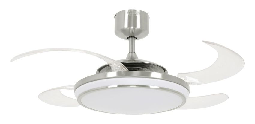
FANAWAY EVO1 LED
CEILING FAN WITH DIMMABLE AND COLOUR
SHIFTING LED LIGHT
INSTALLATION
OPERATION
MAINTENANCE
WARRANTY INFORMATION
CAUTION
READ INSTRUCTIONS CAREFULLY FOR SAFE
INSTALLATION AND FAN OPERATION.
FANAWAY CS LED – V1.0 –MUTIL-2015-10-22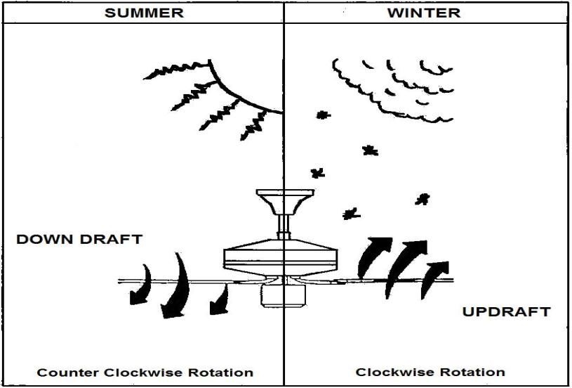
Fanaway EVO1 LED Installation Instructions
                                               CONTENTS
GB   Installation instruction manual .......................................................................................... 2

D    Installationsanleitung ........................................................................................................10

F    Guide d’installation............................................................................................................19

E    Manual de instrucciones de instalación.............................................................................27

I    Manuale delle istruzioni di installazione............................................................................35

NL   Installatiehandleiding.........................................................................................................43

1|Page                                                                                                                       V1.0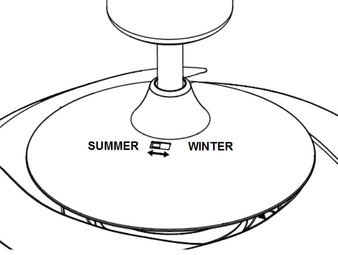
Fanaway EVO1 LED Installation Instructions

                                       THANKYOU FOR YOUR PURCHASE
Thankyou for purchasing this quality Fanaway product. To ensure correct function and safety, please read all
instructions before using the product and keep the instructions for future reference.

                                             SAFETY PRECAUTIONS
The information contained in the following pages has been prepared to ensure you of trouble-free operation of your
ceiling fan.

1.     In Europe: This appliance can be used by children aged from 8 years and above and persons with reduced
       physical, sensory or mental capabilities or lack of experience and knowledge if they have been given
       supervision or instruction concerning use of the appliance in a safe way and understand the hazards involved.
       Children shall not play with the appliance. Cleaning and maintenance shall not be undertaken by children
       without supervision.
2.     In Australia: The appliance is not intended for use by persons (including children) with reduced physical,
       sensory or mental capabilities, or lack of experience and knowledge, unless they have been given supervision
       or instruction concerning use of the appliance by a person responsible for their safety.
3.     Children should be supervised to ensure that they do not play with the appliance.
4.     An all-pole disconnection switch must be incorporated into the fixed wiring, in accordance with local wiring
       rules.
     IN AUSTRALIA:
      WARNING: FOR SAFE USE OF THIS FAN AN ALL-POLE DISCONNECTION SWITCH MUST BE
                                 INCORPORATED INTO THE FIXED WIRING.
                        This is in accordance with the latest standard AS/NZS 60335-1.
              Please note warranty will be void if installed without an all-pole disconnection switch.
             If a fan is connected to a circuit that can be isolated via an all-pole safety switch at the
                       switchboard, then this is considered to be an all-pole isolation switch.

5.          Do not dispose of electrical appliances as unsorted municipal waste, use separate collection facilities.

       Contact your local government for information regarding the collection systems available. If electrical
       appliances are disposed of in landfills or dumps, hazardous substances can leak into the groundwater and get
       into the food chain, damaging your health and well-being.
6.     The structure to which the fan is to be mounted must be capable of supporting a weight of 45kg.
7.     The fan should be mounted so that the blades are at least 2.3 metres above the floor in Europe or 2.1 metres
       above the floor in Australia.
8.     This fan is designed for indoor use only. Mounting the fan in a location where it is subject to water or moisture
       is dangerous and will void the warranty.
9.     Only a licensed electrician should execute the installation.

2|Page                                                                                                      V1.0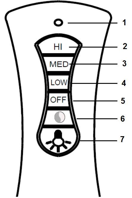
Fanaway EVO1 LED Installation Instructions
                                       BEFORE INSTALLATION
Unpack the fan carefully and identify the parts. Please refer to Fig. 1.

                                                                           Fig. 1

3|Page                                                                       V1.0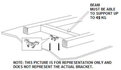
Fanaway EVO1 LED Installation Instructions
1 Mounting bracket x 1 10 Retraction mechanism x 1
2 Canopy screws x 4 11 Lamp base x 1
3 Canopy x 1 12 LED board x 1
4 Down rod x 1 13 Lamp shade x 1
5 Bolt x 1 14 Wooden screws x 2
6 Bolt & pin cover x 1 15 Plastic anchor x 2
7 Pin x 1 16 Balance tapes x 4
8 Top housing x 1 17 Remote x 1 set
9 Blades x 4 18 LED driver x 1
INSTALLING THE MOUNTING BRACKET
The ceiling fan must be installed in a location so that the blades are spaced 300mm from the tip of the blade to
the nearest objects or walls.
Secure the hanging bracket to the ceiling joist or structure that is capable of carrying a load of at least 45kg,
with two long screws provided. Ensure at least 30mm of the screw is threaded into the support.
Fig. 2
NOTE: The bracket screws provided are for use with wooden structures only. For structures other than
wood, the appropriate screw type MUST be used.
Angled ceiling Installation
This fan hanging system supports a maximum 18 degree angled ceiling
installation.
Fig. 3
4|Page V1.0Fanaway EVO1 LED Installation Instructions
INSTALLING THE FAN
1. Installing the down rod
1) Feed the down rod (5) through the canopy (4) and the bolt and pin cover (6).
2) Remove the ball joint by loosening the set screw (3), insert the motor wires through the down rod then
secure the ball joint back to the down rod.
3) Insert the down rod to the coupling (7), line up the coupling holes with the down rod holes and insert the
bolt (8). Then insert the pin (9) to the end of the bolt.
4) Finally secure the down rod and coupling by tightening the two set screws (10) on the coupling. Fig. 4
Fig. 4
2. Carefully lift the fan and place the down rod ball assembly into the spacing allocated in the mounting bracket
and lock the ball into place. Insert the LED driver into the lower layer of the mounting bracket then insert the
remote receiver into the top layer of the mounting bracket. Fig.4
3. Refer to the wiring diagram provided for Electrical Connection/installation. Fig. 5
WARNING: To prevent electrical shock or risk of fire, do not attempt to perform the electrical connection wiring
yourself. All electrical connections must be carried out by a licensed electrician.
NOTE: An additional all pole disconnection switch must be included in the fixed wiring.
Fig. 5
5|Page V1.0Fanaway EVO1 LED Installation Instructions
4. After completing the electrical wiring at the mounting bracket terminal and connecting the remote receiver
power input wires and fixed wiring via the 4-port quick connectors (1); connect the LED driver power input
wires and remote receiver power output wires via the 2-port quick connectors (3); connect the LED driver
PWM signal input wires and remote receiver PWM signal output wires via the 3-port quick connectors (2);
connect the remote receiver fan output and motor input wires via the 4-port quick connectors (4); also connect
the LED driver output wires and LED light wires via the quick connectors (5). Fig. 5
5. Cover the mounting bracket with the canopy. Ensure all electrical wirings are tucked inside the canopy and
that it is not damaged during this step then secure with screws.
Light kit installation
1. Remove the lamp shade from the lamp base by turning it anti-clockwise.
2. Loosen the screw (1) from the base bracket (3). Align the two slot screws (2) with the keyhole slots of the lamp
base (4). Fig.6
3. Turn the lamp base counterclockwise until the slot screws are firmly at the end of the slots.
4. Secure screw 1 back to the base bracket. Tighten all three screws. Do not over-tighten.
5. Connect the upper plug (1) from the driver to the lower socket (1) in the LED board (2). Fig.7
6. Finally install the lamp shade to the lamp base by turning it clockwise (5 – Fig.6).
Fig. 6 Fig. 7
USING YOUR CEILING FAN
REMOTE CONTROL
Your ceiling fan is controlled via the remote control. There are 4 buttons (HI, MED, LOW, OFF) to control the fan
speed and one button to control light on/off and dimming function. Fig. 10
Before operating the remote, the following must be considered.
- 2 x AAA 1.5V (size) batteries are required to operate the remote control. Remove the battery cover from
the back of the remote and insert 2 x AAA batteries. Ensure the polarities are correct as shown in the
battery compartment. (Batteries not included).
- The remote (transmitter) and receiver must be configured so that communication between each other is
paired up. This is achieved by setting the DIP switch on the receiver and remote on the same setting.
Note: The DIP switch assembly has 4 switches which can be setup to 16 different transmitting code
combinations. This is practical when there is more than 1 remote/receiver pair operating locally or in the
same room.
6|Page V1.0Fanaway EVO1 LED Installation Instructions
Note: To access the receiver DIP switches, remove the DIP switch cover.
Fig. 8 Remote battery compartment Fig. 9 Receiver DIP switch
OPERATING THE REMOTE:
Before you start using the remote, take the time to read through this section and
get familiar with the buttons and function of each button.
1. LED Indicator
The red LED indicator on the top of the transmitter will flash when the buttons are
active.
BUTTONS ON THE REMOTE
2. HI: Press this button to set the fan running at High speed.
3. MED: Press this button to set the fan running at Medium speed.
4. LOW: Press this button to set the fan running at Low speed.
5. OFF: Press this button to turn OFF the fan.
6. : Press this button to change the color temperature in the following order: Fig. 10
3000K → 5000K → 4000K → 3000K
7. : Press this button to turn ON/OFF the light and press and hold the button to access the light dimming
function.
The remote has memory function. If the fan or light is turned off by the isolating switch, it will memorise and recover
the last status when turned on next.
REVERSING SWITCH
Your ceiling fan can operate in either summer or winter mode.
SUMMER Mode: The reverse switch shall be in the “LEFT” (SUMMER) position to make the fan rotate in an
anticlockwise direction. The airflow will be directed downwards, for cooling in summer.
WINTER Mode: The reverse switch shall be in the “RIGHT” (WINTER) position to make the fan rotate in a
clockwise direction. The airflow will be directed upwards assisting in the circulation of warm air, for energy
conservation in winter.
7|Page V1.0Fanaway EVO1 LED Installation Instructions
Reverse Switch Fig. 11
AFTER INSTALLATION
WOBBLE:
The fan blades have been adjusted in the factory to minimize any wobble.
NOTE: CEILING FANS TEND TO MOVE DURING OPERATION DUE TO THE FACT THAT THEY ARE
MOUNTED ON A RUBBER GROMMET. IF THE FAN WAS MOUNTED RIGIDLY TO THE CEILING IT WOULD
CAUSE EXCESSIVE VIBRATION. MOVEMENT OF A FEW CENTIMETRES IS QUITE ACCEPTABLE AND
DOES NOT SUGGEST ANY PROBLEM.
TO REDUCE THE FAN WOBBLE: PLEASE CHECK THAT ALL SCREWS WHICH SECURED THE MOUNTING
BRACKET AND DOWN ROD ARE SECURE.
BALANCING A WOBBLING CEILING FAN:
For your convenience, a Balancing Kit is included; please follow this procedure when balancing the fan:
1) Install the fan without the light dome before balancing the fan.
2) Define the base plate into four areas (point A, B, C & D). Use one
weight from the balance kit to lightly stick on the edge of the base
plate (say point A), if the wobble worsens, then take off the balance
kit and lightly stick it on the opposite side (say point B); if the
wobble is worse, then go to the adjacent point C or D, if the wobble
gets better, then securely stick on the weight at this location on the
base plate.
3) After balancing the fan, assemble the light dome to the light base.
NOISE:
When it is quiet (especially at night) you may hear occasional small noises. Slight power fluctuations and frequency
signals superimposed in the electricity for off-peak hot water control, may cause a change in fan motor noise. This
is normal. Please allow a 24-hour “breaking -in” period, most noises associated with a new fan disappear during
this time. The manufacturer’s warranty covers actual faults that may develop and NOT minor complaints such as
hearing the motor run – All electric motors are audible to some extent.
8|Page V1.0Fanaway EVO1 LED Installation Instructions
CARE AND CLEANING
1) Periodic cleaning of your ceiling fan is the only maintenance required. Use a soft brush or lint free cloth to
avoid scratching the paint finish. Please turn off electricity power when you do so.
2) Do not use water when cleaning your ceiling fan. It could damage the motor or the blades and create the
possibility of an electrical shock.
3) The motor has a permanently lubricated ball bearing so there is no need to oil.
NOTE: Always turn off the power and disconnect the female plug 1 and male plug 1 before attempting to clean your
fan.
TECHNICAL INFORMATION
FAN models Rated Voltage Rated power (motor) Light power
40W,
3000K/5000K/4000K
FANAWAY LED FAN 220-240VAC 60W
LED driver model:
KLC-038-A2M
WARRANTY CONDITIONS
IN AUSTRALIA / NEW ZEALAND – Please refer to the separate WARRANTY STATEMENT.
IN EUROPE – If you are a European customer please contact the retail outlet where the fan was purchased for a
warranty service.
9|Page V1.0Fanaway EVO1 LED Installation Instructions
WIR GRATULIEREN ZUM KAUF DIESES GERÄTES
Wir gratulieren zum Kauf dieses Qualitätsproduktes von Fanaway. Bitte lesen Sie die Sicherheitshinweise
vollständig und sorgfältig durch, um den ordnungsgemäßen und sicheren Einsatz des Gerätes zu gewährleisten.
SICHERHEITSHINWEISE
Die Hinweise auf den nachfolgenden Seiten erklären den sicheren und störungsfreien Betrieb Ihres
Deckenventilators.
1) Europa: Dieses Gerät darf nur von Kindern in einem Alter von 8 Jahren und darüber sowie von Personen mit
eingeschränkten körperlichen, geistigen oder sensorialen Fähigkeiten oder mangelnder Erfahrung und
Wissen nur unter Aufsicht verwendet werden, oder nachdem diese Anweisungen über die sichere
Verwendung des Gerätes erhalten haben und die Risiken verstehen. Das Säubern und die Instandhaltung
darf von Kindern nur unter Aufsicht vorgenommen werden. Kinder dürfen nicht mit dem Gerät spielen.
2) Australia: This appliance is not intended for use by young children or infirm persons unless they have been
adequately supervised by a responsible person to ensure that they can use the appliance safely.
3) Kinder müssen beaufsichtigt werden, um sicher zu gehen, dass sie nicht mit dem Gerät spielen.
4) Eine allpolige Abschaltung muss gemäß den Verkabelungsvorgaben in die feste Verkabelung integriert sein.
5) Entsorgen Sie elektrische Geräte nicht als unsortierten Restmüll, sondern nutzen Sie separate
Sammelvorrichtungen. Erkundigen Sie sich bei Ihrer Gemeindeverwaltung über mögliche verfügbare
Sammelsysteme. Wenn elektrische Geräte auf Mülldeponien entsorgt werden, besteht die Gefahr, dass
Gefahrstoffe in das Grundwasser und somit in Nahrungskette entweichen, was Ihrer Gesundheit und Ihrem
Wohlbefinden schaden kann.
6) Die Vorrichtung, an welcher der Ventilator angebracht wird, sollte mindestens 45kg Gewicht tragen können.
7) Für Europa: Der Ventilator sollte so angebracht sein, dass seine Rotorblätter mindestens 2,3 Meter vom
Fußboden entfernt sind.
8) Für Australien: Der Ventilator sollte so angebracht sein, dass seine Rotorblätter mindestens 2,1 Meter vom
Fußboden entfernt sind.
9) Dieser Ventilator ist nur zum Gebrauch in Innenräumen vorgesehen. Das Anbringen des Ventilators an Orten,
an denen er Wasser oder Feuchtigkeit ausgesetzt ist, ist gefährlich.
10) Nur konzessionierte Elektriker dürfen die Installation durchführen.
10 | P a g e V1.0Fanaway EVO1 LED Installation Instructions
VOR DER INSTALLATION ZU BEACHTEN
Bitte packen Sie das Gerät aus, und stellen Sie sicher, dass alle Teile im Versandkarton enthalten sind. Bitte
beachten Sie Abb. 1.
Abb. 1
11 | P a g e V1.0Fanaway EVO1 LED Installation Instructions
1 Deckenhalterung x 1 10 Einzugsmechanismus x 1
2 Abdeckschirmschrauben x 4 11 Lampenfassung x 1
3 Abdeckschirm x 1 12 LED-Platine x 1
4 Hängestange x 1 13 Lampenschirm x 1
5 Sicherungsbolzen x 1 14 Holzschrauben x 2
6 Abdeckung für Bolzen & Stift x 1 15 Plastikanker x 2
7 Stift x 1 16 Balance-Streifen x 4
8 Obere Gehäusehälfte x 1 17 Fernbedienung x 1 set
9 Ventilatorflügel x 4 18 LED-Treiber x 1
INSTALLATION DER DECKENHALTERUNG
Der Deckenventilator muss an einem Ort so installiert werden, dass die Spitzen der Ventilatorflügel
mindestens 300mm vom nächsten Gegenstand oder der Wand entfernt sind.
Befestigen Sie die Deckenhalterung nur an Decken oder Deckenverschalungen und anderen
Deckenstrukturen, die ein Gewicht von mindestens 45KG sicher halten können; verwenden Sie dazu die zwei
langen Schrauben, die mit dem Ventilator ausgeliefert wurden. Stellen Sie sicher, dass die Schraubengewinde
mindestens 30mm in das Material eingedreht sind, woran die Halterung für den Ventilator befestigt ist.
Abb. 2
HINWEIS: Die mitgelieferten Halteschrauben sind nur für Tragestrukturen aus Holz geeignet. Für
Tragestrukturen die nicht aus Holz sind, MUSS der dafür geeignete und zugelassene Schraubentyp
verwendet werden.
Installation an geneigten Decken
Dieses Halterungssystem ist nur für die Aufhängung an geneigten Decken mit
einem Neigungswinkel von bis zu 18 geeignet.
Abb. 3
12 | P a g e V1.0Fanaway EVO1 LED Installation Instructions
MONTAGE
1. Installation der Hängestange
1) Führen Sie die Hängestange (5) durch den Schirm (4) und die Abdeckung für den Bolzen und Stift (6).
2) Entfernen Sie das Kugelgelenk, indem Sie die Sicherungsschraube (3) entfernen, führen Sie die
Motorkabel durch die Hängestange und sichern Sie das Kugelgelenk anschließend wieder an der
Hängestange.
3) Führen Sie die Hängestange durch die Kupplung (7), Richten Sie die Bohrungen der Kupplung auf die
Bohrungen der Hängestange aus, und führen Sie den Bolzen (8) ein. Führen Sie nun den Sicherungsstift
(9) am überstehenden Ende des Stifts ein.
4) Sichern Sie abschließend die Hängestange an der Kupplung, indem Sie die zwei Fixierschrauben (10)
an der Kupplung festziehen.
Abb. 4
2. Heben Sie den Ventilator an und platzieren Sie die Kugel der Hängestangenhalterung in der Aussparung der
Deckenhalterung und sichern Sie die Kugelhalterung fest und sicher. Führen Sie die Treiberelektronik für die
LED-Lampe in den unteren Teil der Halterung ein, und platzieren Sie anschließend den Empfänger für die
Fernbedineung in der oben in der Deckenhalterung.
3. Für Einzelheiten zu den elektrischen Anschlüssen/Montage beziehen Sie sich bitte auf den mitgelieferten
Schaltplan. Abb.5
ACHTUNG: Um einen elektrischen Kurzschluß oder Brand zu vermeiden, bitte nicht versuchen, den
Elektroanschluss selbst herzustellen. Alle elektrischen Anschlüsse müssen von einer Elektrofachkraft
ausgeführt werden.
HINWEIS: Alle festen Verkabelungen müssen einen zusätzlichen allpoligen Trennschalter besitzen.
13 | P a g e V1.0Fanaway EVO1 LED Installation Instructions
Abb. 5
4. Nach Abschluß der elektrischen Anschlußarbeiten an den Kontaktklemmen der Decekenhalterung, und nach
Anschluß der Verbindungskabel für die Fernbedienung und der fest installierten Kabelverbindung am
4-Poligen Schnellkontaktblock (1); verbinden Sie die Stromkabel für den LED-Treiber und die Steuerung der
Fernbedienung über die 2-poligen Schnellkontaktblöcke (3); verbinden Sie die PWM Signalkabel für den
LED-Treiber und die PWM Signalkabel für die Fernbedienung mittels des 3-poligen Schnellkontaktblocks (2);
Verbinden Sie die Augangskable des Fernbedienung und die Motoranschlußkable mittels des 4-poligen
Schnellkontaktblocks (4); verbinden Sie abschließend die LED-Treiberkabel und die LED Lichtkabel mit dem
3-Poligen Schnellkontaktblock (5). Abb 5.
5. Die Deckenhalterung mit der Canopy-Abdeckung abdecken. Nachdem Sie sich vergewissert haben, dass alle
elektrischen Kabel im Canopy (Baldachin) stecken und bei der Ausführung dieses Schritts nicht beschädigt
wurden, den Canopy (Baldachin) fest anschrauben.
Abb. 5
LICHTBAUSATZ INSTALLATION
1) Lösen Sie die Schraube (1) von der Basis der Deckenhalterung (3). Richten Sie die zwei Schlitzschrauben (2)
auf die Schlitze an der Lampenbasis (4) aus. Abb. 6
2) Drehen Sie die Lampenbasis im Gegenuhrzeigersinn bis die Schlitzschrauben fest in den Enden der Schlitze
sitzen.
3) Sichern Sie Schraube 1 wieder an der Basishalterung. Ziehen Sie alle drei Schrauben fest. Ziehen Sie die
Schrauben nicht zu fest an.
4) Verbinden Sie den oberen Stecker (1) vom Treiber mit der unteren Buchse (1) auf der LED-Platine (2). Abb.7
5) Installieren Sie abschließend die Lampe in der Lampenbasis, indem Sie diese im Uhrzeigersinn drehen. (5 –
Abb. 6).
14 | P a g e V1.0Fanaway EVO1 LED Installation Instructions
Fig. 6 Fig. 7
DER EINSATZ DES DECKENVENTILATORS
REMOTE CONTROL
Ihr Deckenventilator wird über die Fernbedienung angesteuert. Sie finden 4 Tasten (HOCH, MITTEL, NIEDRIG,
AUS) für die Steuerung der Ventilatorgeschwindigkeit, sowie einen EIN/AUS-Schalter, der auch als Dimmer-Regler
funktioniert. Abb. 10
Before operating the remote, the following must be considered.
- Die Fernbedienung benötigt 2 Batterien mit 1,5V des Typs AAA (Größe) für den Betrieb. Nehmen Sie die
Batteriefachabdeckung an der Rückseite der Fernbedienung ab, und legen Sie 2 Batterien des Typs AAA ein.
Stellen Sie sicher, dass die Polarisierungsangaben entsprechend den Angaben im Batteriefach aufeinander
ausgerichtet sich. Vergewissern Sie sich, dass alle Batterien neu sind (Batterien sind nicht im Lieferumfang
enthalten).
- Der Sender und der Empfänger müssen für den Betrieb aufeinander abgestimmt und paarweise konfiguriert
werden. Dies erreichen Sie dadurch, dass Sie die DIP-Schalter am Empfänger und am Sender in die gleiche
Einstellung bringen.
Hinweis: Die DIP-Schalterleiste verfügt über 4 Schaltermodule, mit denen entsprechend 16 verschiedene
Sendekodekombinationen eingestellt werden können. Dies ist besonders dann nützlich, wenn mehr als 1
Fernbedienung/Empfängereinheit in der gleichen Umgebung oder im gleichen Raum betrieben werden.
Hinweis: Um auf die DIP-Schalterleiste zugreifen zu können, müssen Sie die Abdeckung für die DIP-Schalter
abnehmen.
Abb.8 Remote battery compartment Abb.9 Receiver DIP switch
15 | P a g e V1.0Fanaway EVO1 LED Installation Instructions
OPERATING THE REMOTE:
Bevor Sie die Fernbedienung erstmals einsetzen, sollten Sie sich die Zeit nehmen und den folgenden Abschnitt
lesen, um sich mit den Funktionen der einzelnen Tasten vertraut zu machen.
1. LED-Indikator: Der rote LED-Indikator an der Oberseite der Fernbedienung
blinkt während die Funktion einer Taste ausgeführt wird.
2. HI: Betätigen Sie die Taste, um die Geschwindigkeit des Ventilators auf
„Hoch“ einzustellen.
3. MED: Betätigen Sie die Taste, um die Geschwindigkeit des Ventilators auf
„Medium“ einzustellen.
4. LOW: Betätigen Sie die Taste, um die Geschwindigkeit des Ventilators auf
„Niedrig“ einzustellen.
5. OFF: Betätigen Sie die Taste, um den Ventilator „AUS“ zu schalten.
6. : Drücken Sie diese Taste um die Farbtemperatur des Lichts wie folgt zu
ändern: 3000K → 5000K → 4000K → 3000K
Abb. 10
7. : Betätigen Sie die Taste, um das Licht EIN/AUS zu schalten. Hlaten Sie
die Taste gedrückt, um die Dimmerfunktion zu aktivieren
Die Fernsteuerung verfügt über eine integrierte Speicherfunktion. Wenn der Ventilator oder das Licht mittels des
Wandschalters ausgeschaltet werden, dann wird die aktuelle Einstellung gespeichert, und die Einstellungen
werden beim erneuten Einschalten des Ventilators wieder hergestellt.
RÜCKLAUFFUNKTION
Der Ventilator kann sowohl im Vorlauf als auch im Rücklauf betrieben werden.
SOMMERBETRIEB: Wenn der Schalter für die Rücklauffunktion auf “down” (SOMMER) steht, dreht der Ventilator
sich gegen den Uhrzeigersinn. Die Luftbewegung wird nach unten gelenkt und bringt im Sommer den
gewünschten Abkühlungseffekt.
WINTERBETRIEB: Wenn der Schalter für die Rücklauffunktion auf “up” (WINTER) steht, dreht sich der Ventilator
im Uhrzeigersinn. Die Luftbewegung wird nach oben gelenkt, um im Winter Energie zu sparen.
Umkehrschalter Abb. 11
16 | P a g e V1.0Fanaway EVO1 LED Installation Instructions
NACH DER INSTALLATION
UNWUCHT:
Die Ventilatorflügel wurden im Werk justiert, um die Unwucht zu minimieren.
HINWEIS: DA DECKENVENTILATOREN AN EINER GUMMI-ISOLIERSCHEIBE MONTIERT SIND, TENDIEREN
SIE DAZU, WÄHREND DES BETRIEBS IN BEWEGUNG ZU SEIN. FALLS DER VENTILATOR ZU FEST AN DER
DECKE BEFESTIGT WIRD, KANN DIES ZU ÜBERMÄSSIGER VIBRATION FÜHREN. MEHRERE ZENTIMETER
BEWEGUNGSSPIELRAUM SIND AKZEPTABEL UND STELLEN KEIN PROBLEM DAR.
REDUZIEREN VON WACKELN: ÜBERPRÜFEN SIE, OB ALLE SCHRAUBEN DER BEFESTIGUNGSPLATTEN
UND DES HÄNGEROHRS FEST SITZEN.
AUSBALANCIEREN EINES WACKELNDEN DECKENVENTILATORS:
Um Ihnen den Vorgang zu erleichtern, wird der Deckenventilator mit Unwucht-Gewichten ausgeliefert; bitte
beachten Sie die nachfolgenden Hinweise zur Ausbalancierung des
Deckenventilators:
4) Installieren Sie den Ventilator ohne Lichtdom, bevor Sie die
Ausbalancierung des Ventilators beginnen.
5) Teilen Sie die Grundplatte in vier Quadranten ein (Punkt A, B, C &
D). Setzen Sie nun eines der Gewichte auf die Kante der
Grundplatte auf (z.B. Punkt A), wenn die Unwucht größer wird,
dann nehmen Sie das Gewicht ab, und bringen Sie dieses an der
Gegenüberliegenden Seite (z.B. Punkt B) an; wenn die Unwucht
auch hier größer wird, dann bringen Sie das Gewicht anschließend
an Punkt C oder Punkt D an. Wenn die Unwucht anschließend
geringer ist, dann bringen Sie das Gewicht fest an dieser Stelle der Grundplatte an.
6) Bringen Sie den Lichtdom nach der Ausbalancierung auf der Grundplatte an.
GERÄUSCHE:
In einer geräuscharmen Umgebung kann es gelegentlich (vor allem nachts) vorkommen, dass leise Geräusche
des Ventilators zu vernehmen sind. Das Geräusch des Ventilatormotors kann sich durch geringe
Stromschwankungen und Abweichungen in der Stromfrequenz ändern. Das ist völlig normal. Die meisten
Geräusche eines neuen Ventilators verschwinden nach einer „Eingewöhnungszeit“ von etwa 24 Stunden. Die
Garantie des Herstellers erstreckt sich nur auf tatsächliche Mängel, die u. U. auftreten können, und NICHT auf
geringfügige Beschwerden, wie zum Beispiel hörbare Motorgeräusche. - Jeder Elektromotor ist in gewissem
Umfang hörbar.
REINIGUNGS- UND PFLEGEHINWEISE:
1. Außer gelegentlicher Reinigung bedarf dieser Ventilator keiner Wartung. Verwenden Sie hierfür eine
weiche Bürste oder einen flusenfreien Lappen, damit die Oberfläche nicht verkratzt wird. Der Ventilator
sollte zur Reinigung ausgeschaltet werden.
2. Den Ventilator nicht mit Wasser reinigen. Wasser kann den Motor oder die Flügelblätter beschädigen und
zu Stromschlägen führen.
3. Der Motor ist mit schmierungsfreien Kugellagern ausgerüstet. Er muss nicht geölt werden.
17 | P a g e V1.0Fanaway EVO1 LED Installation Instructions
HINWEIS: Schalten Sie den Trennschalter immer aus, und trennen Sie anschließend die Buchse 1 von
Stecker 1, bevor Sie versuchen Ihren Ventilator zu reinigen.
TECHNISCHE INFORMATIONEN
Nennleistung
VENTILATOR-Modelle Nennspannung Nennleistung (Motor)
Beleuchtung
40W,
3000K/4000K/5000K
FANAWAY LED
220-240VAC 60W LED-Beleuchtungssatz
VENTILATOR
mit Treiber Modell:
KLC-038-A2M
GARANTIEBEDINGUNGEN
IN AUSTRALIA / NEW ZEALAND – Bitte beachten Sie die separate GARANTIEERKLÄRUNG.
IN EUROPA – Falls Sie ein Kunde in Europa sind, dann treten Sie für eventuelle Garantieleistungen bitte mit dem
Fachgeschäft in Kontakt, bei dem Sie den Ventilator gekauft haben.
18 | P a g e V1.0Fanaway EVO1 LED Installation Instructions
MERCI POUR VOTRE ACQUISITION
Merci d’avoir acheté ce produit de qualité de FANAWAY. Pour garantiser la securité et le fonctionnement correct,
lire et sauver soigneusement tous les instructions avant d’utiliser le produit.
PRECAUTIONS à PRENDRE
L’information que les pages suivantes contiennent a été préparée pour assurer l’operation rapide de votre
ventilateur au plafond.
1. Europe: Cet appareil peut être utilisé par des enfants âgés de 8 ans et plus et des personnes ayant des
capacités physiques, sensorielles ou mentales réduites ou un manque d'expérience et de connaissance s'ils
sont sous surveillance ou ont reçu des instructions au préalable concernant l'utilisation de l'appareil en toute
sécurité et s’ils comprennent les risques impliqués. Le nettoyage et l’entretien ne doivent pas être faits par des
enfants sans une surveillance.
2. Australie: Cet appareil n'est pas destiné à être utilisé par de jeunes enfants ou des personnes handicapées à
moins qu'ils ne soient adéquatement supervisés par une personne responsable pour s'assurer qu'ils puissent
utiliser l'appareil en toute sécurité.
3. Les enfants doivent être surveillés pour s'assurer qu'ils ne jouent pas avec l'appareil.
4. Un interrupteur de déconnexion omnipolaire doit être incorporé dans le câblage fixe en conformité avec les
règles de câblage.
5. Ne jetez pas les appareils électriques dans les ordures ménagères, utiliser les installations de
collecte sélective. Contactez votre municipalité pour obtenir des informations concernant les systèmes de
collecte disponibles. Si les appareils électriques sont détruits dans des décharges ou dépotoirs, des
substances dangereuses peuvent s'infiltrer dans les eaux souterraines et entrer dans la chaîne alimentaire, ce
qui pourrait nuire à votre santé et votre bien-être.
6. La structure sur laquelle le ventilateur doit être monté doit être capable de supporter un poids de 45kg.
7. Le ventilateur doit être monté de telle sorte que les pales soient au moins 2.3 mètres au-dessus du sol pour
l'Europe.
8. Le ventilateur doit être monté de telle sorte que les lames soient au moins 2.1 mètres au-dessus du sol pour
l'Australie.
9. Ce ventilateur est adapté pour une utilisation en intérieur. Le montage du ventilateur dans un endroit où il est
exposé à l'eau ou à l'humidité est dangereux.
10. Seul un électricien agréé doit exécuter l'installation.
19 | P a g e V1.0Fanaway EVO1 LED Installation Instructions
AVANT L’INSTALLATION
Déballer le ventilateur et identifier les pièces avec prudence. Veuillez référer à Fig 1.
Fig. 1
20 | P a g e V1.0Fanaway EVO1 LED Installation Instructions
1 Support de montage x 1 10 Mécanisme de rétraction x 1
2 Vis pour couvercle x 4 11 Pied de lampe x 1
3 Couvercle x 1 12 Carte à LED x 1
4 Tige descendante x 1 13 Abat-jour x 1
5 Boulon x 1 14 Vis à bois x 2
6 Couvercle de boulon & de goupille x 1 15 Cheville en plastique x 2
7 Goupille x 1 16 Adhésif x 4
8 Boitier supérieur x 1 17 Télécommande manuelle x 1 jeu
9 Pales x 4 18 Pilote de DEL x1
INSTALLATION DE SUPPORT DE FIXATION
Le ventilateur doit être installé dans une position où les pales sont 300mm en espace de chaque point de pale
même au mur le plus proche.
Assurer le support de suspension à la solive de plafond ou structure qui est capable de transporter une
charge de 45KG au moins avec l’utilisation de deux vis longues. Assurer qu’au moins 30mm de vis soit inséré
au support.
Fig. 2
REMARQUE: Les vis de support doivent être seulement utilisées sur les structures à bois. Autre que les
bois, il FAUT utiliser la vis correcte pour les autres structures.
Installation au Plafond Incliné
Ce système de suspension du ventilateur transporte au maximum 18 degré
de plafond incliné.
Fig. 3
21 | P a g e V1.0Fanaway EVO1 LED Installation Instructions
INSTALLATION DU VENTILATEUR
1. Installation de la tige descendante
1) Monter la tige descendante (5) à travers le couvercle(4) et le couvercle de boulon et de goupille (6).
2) Retirer le joint à rotule en desserrant la vis de pression (3) et insérer les câbles du moteur à travers la tige
descendante et puis fixer le joint à rotule à la tige descendante.
3) Insérer la tige descendante à l'accouplement (7), aligner les trous de couplage avec les trous de tige
descendante et insérer le boulon (8). Ensuite, insérer la goupille (9) à l'extrémité du boulon.
4) Enfin fixer la tige descendante et le couplage en serrant les deux vis de réglage (10) sur l'accouplement.
Figure. 4
Fig. 4
2. Soulevez soigneusement le ventilateur et placez le bas de la tige de l'ensemble à bille dans l'espacement
alloué dans le support de montage et verrouiller la bille en place. Insérer la commande de DEL dans la couche
inférieure du support de montage, puis insérez le récepteur à distance dans la couche supérieure du support
de montage. Fig. 4
3. Consultez le schéma de câblage prévu pour la connexion/installation électrique. Fig.5.
AVERTISSEMENT: Pour éviter le risqué d’électrocution ou le risque d’incendie, ne tentez pas d’exécuter
vous-même la connexion du câblage électrique. Toutes les connexions électriques doivent être effectuées par
un électricien qualifié agréé.
REMARQUE: Un commutateur de déconnexion omnipolaire supplémentaire doit être inclus dans le câblage
fixe.
Fig. 5
22 | P a g e V1.0Fanaway EVO1 LED Installation Instructions
4. Après avoir terminé le câblage électrique au terminal du support de montage et le raccordement des câbles d’
d'entrée de la puissance du récepteur à distance et le câblage fixe via les 4 ports de connecteurs rapides (1);
connectez les câbles d'entrée de la puissance de commande de LED et la puissance de réception à distance
via les 2 ports de connecteurs rapides (3); connectez les câbles d'entrée du signal PWM de la commande de
DEL et câbles de sortie du signal PWM du récepteur à distance via les 3 ports de connecteurs rapides (2);
connectez la sortie du ventilateur du récepteur à distance et les câbles d'entrée du moteur via les 4 ports de
connecteurs rapides (4); également connecter les câbles de sortie de la commande de DEL et les câbles de la
lampe de la DEL via les 3 ports de connecteurs rapides (5). Fig. 5
5. Couvrez le support de montage avec le couvercle d’auvent. Assurez-vous que les câbles électriques sont
groupés à l’intérieur de l’auvent et qu'ils ne sont pas endommagés pendant cette étape et fixez-les avec des
vis.
LUMIÈRE KIT INSTALLATION
1. Desserrer la vis (1) à partir du support de base (3). Aligner les deux vis à fente (2) avec les trous de serrure du
pied de la lampe (4). Figure 6
2. Tournez le pied de la lampe dans le sens antihoraire jusqu'à ce que les vis à fente soient bien à la fin des
fentes.
3. Serrer la vis 1 vers le support de base. Serrer les trois vis. Ne pas trop serrer.
4. Branchez le bouchon supérieur (1) depuis le pilote à la prise inférieure (1) de la carte à LED (2). Figure 7
5. Enfin, fixer l’ampoule au pied de la lampe en tournant vers la droite (5 - Figure 6).
Fig. 6 Fig. 7
UTILISER VOTRE VENTILATEUR AU PLAFOND
REMOTE CONTROL
Votre ventilateur de plafond est contrôlé via la télécommande. Il ya 4 boutons (HI, MED, LOW, OFF) pour contrôler
la vitesse du ventilateur et un bouton pour contrôler la lumière on / off et la fonction de réduction d'intensité
lumineuse. Fig. 10
Before operating the remote, the following must be considered.
- 2 piles x AAA 1,5V (taille) sont nécessaires pour utiliser la télécommande. Retirer le couvercle du compartiment
à piles à l'arrière de la télécommande et insérer 2 piles AAA. Assurez-vous que les polarités sont exactes
23 | P a g e V1.0Fanaway EVO1 LED Installation Instructions
comme indiqué à l'intérieur du compartiment à piles. Et que les piles sont toutes neuves (les piles ne sont pas
incluses).
- L'émetteur et le récepteur doivent être configurés de façon à ce que la communication entre les uns et les
autres soit appariée. Cet appariement est obtenu en réglant le commutateur du DIP du récepteur et de
l'émetteur au même réglage.
Remarque: L'assemblage du commutateur du DIP compte 4 commutateurs qui peuvent être régler en 16
combinaisons de code d'émission différentes. Ceci est pratique lorsqu'il existe plus d'une paire constituée
d'une télécommande/récepteur fonctionnant localement ou dans la même salle.
Remarque: Pour accéder aux commutateurs DIP du récepteur, retirer le couvercle du commutateur DIP.
Fig. 8 Remote battery compartment Fig. 9 Receiver DIP switch
OPERATING THE REMOTE:
Avant d'utiliser la télécommande, prenez le soin de lire intégralement cette section et de se familiariser avec la
fonction de chaque bouton.
1. Indicateur LED: L'indicateur LED rouge situé sur la partie supérieure de
l'émetteur clignotera lorsque les boutons sont activés.
2. HI: Appuyer le bouton pour régler la vitesse de fonctionnement du ventilateur
à élevé.
3. MED: Appuyer le bouton pour régler la vitesse de fonctionnement du
ventilateur à moyen.
4. LOW: Appuyer le bouton pour régler la vitesse de fonctionnement du
ventilateur à faible.
5. OFF: Appuyer le bouton pour ARRETER le ventilateur.
6. : Appuyez sur le bouton pour changer la température de couleur dans
l'ordre suivant: 3000K → 5000K → 4000K → 3000K
Fig. 10
7. : Appuyez sur le bouton pour ON/OFF la lumière et appuyez sur le bouton
pour accéder à la fonction de gradation de lumière.
La télécommande dispose d’une fonction mémoire. Si le ventilateur ou l'éclairage est arrêté par le commutateur
mural, la télécommande mémorisera et récupèrera le dernier état lors du prochain allumage.
24 | P a g e V1.0Fanaway EVO1 LED Installation Instructions
FONCTIONNEMENT INVERSÉ
Votre ventilateur peut être opéré en mode ventilateur et en mode ventilateur inversé.
Mode ÉTÉ: Positionner l'interrupteur inverseur sur “LEFT” (SUMMER) afin de faire tourner le ventilateur dans le
sens inverse des aiguilles du montre. Le jet d'air orienté vers le bas crée un courant d'air frais.
Mode HIVER: Positionner l'interrupteur inverseur sur “RIGHT” (WINTER) afin de faire tourner le ventilateur dans le
sens des aiguilles d'une montre. La répartition de l'air ambiant chauffé vers le haut favorise les économies
d'énergie.
Commutateur d’inversion Fig. 11
APRÈS L'INSTALLATION
OSCILLATION:
Les pales du ventilateur ont été ajustées à l'usine afin de minimiser toute oscillation.
REMARQUE: LES VENTILATEURS DE PLAFOND ONT TENDANCE A SE DEPLACER PENDANT LE
FONCTIONNEMENT DUE AU FAIT QU’ILS SONT MONTES A L’ŒILLET DE CAOUTCHOUC. SI LE
VENTILATEUR A ETE MONTE DE FAÇON RIGIDE AU PLAFOND CELA CAUSERAIT DES VIBRATIONS
EXCESSIVES. MOUVEMENT A QUELQUES CENTIMETRES EST TOUT A FAIT ACCEPTABLE ET NE
SUGGERE AUCUN PROBLEME.
POUR RÉDUIRE L’OSCILLATION DU VENTILATEUR: VEUILLEZ VÉRIFIER QUE TOUTES LES VIS QUI
ASSURERONT LE SUPPORT DU MONTAGE ET LA TIGE DESCENDANTE SONT SÉCURISÉS.
BALANCING A WOBBLING CEILING FAN:
For your convenience, a Balancing Kit is included; please follow this procedure when balancing the fan:
ÉQUILIBRER UN VENTILATEUR DE PLAFOND OSCILLANT:
Pour votre commodité, un Kit d'équilibrage est inclus; veuillez suivre
cette procédure lors de l'équilibrage du ventilateur:
1) Installez le ventilateur sans plafonnier avant d'équilibrer le
ventilateur.
2) Définir la plaque de base en quatre zones (point A, B, C & D).
Utilisez un poids de la trousse de l'équilibre en tenir légèrement sur
le bord de la plaque de base (disons point A), si l'oscillation
25 | P a g e V1.0Fanaway EVO1 LED Installation Instructions
s’aggrave, puis décoller le kit de l'équilibre et de le coller sur la partie légère côté opposé (disons point B); Si
l'oscillation s'aggrave, puis enlever le kit équilibre et coller légèrement sur le côté opposé (disons point B) ; Si
l'oscillation est pire, puis allez dans l'adjacent point C ou D, si l'oscillation s'améliore, puis coller solidement
sur le poids à cet endroit sur la plaque de base.
3) Après équilibrage du ventilateur, assembler le dôme de lumière à la base de la lumière.
BRUIT:
Quand tout est calme (surtout la nuit), vous entendrez peut-être des petits bruits occasionnels. Les fluctuations de
puissance légères et les signales fréquences superposées dans l'électricité pour la maitrise creuse de l'eau
chaude, peuvent provoquer un changement dans le bruit du moteur du ventilateur. Ceci est normal. Veillez
permettre un « interrompre » d’une période de 24 heures, la plupart des bruits associés à un nouveau ventilateur
disparaissent avec le temps. La garantie du fabricant couvre les défauts réels qui peuvent se développer et non
les plaintes mineurs telle que, entendre le fonctionnement du moteur - Tous les moteurs électriques sont audibles
dans une certaine mesure.
ENTRETIEN ET NETTOYAGE
1) Le nettoyage périodique de votre ventilateur de plafond est le seul entretien nécessaire. Utilisez une brosse
douce ou un chiffon non pelucheux pour éviter rayer la peinture de finition. Veillez mettre hors tension
l'alimentation électrique lorsque vous le faites.
2) Ne pas utiliser de l'eau lors du nettoyage de votre ventilateur de plafond. Cela pourrait endommager le moteur
ou les lames et la possibilité de créer un choc électrique.
3) Moteur est lubrifiés en permanence roulement à billes. Pas besoin d'huile
REMARQUE: Toujours mettre hors tension l'appareil et débrancher la fiche mâle et une prise femelle avant
d’essayer de nettoyer votre ventilateur.
INFORMATION TECHNIQUE
Puissance nominale
Modèles de VENTILATEUR Tension nominale Puissance lumineuse
(moteur)
40W,
VENTILATEUR À LED 3000K/4000K/5000K
220-240VAC 60W
FANAWAY Modèle de pilote LED:
KLC-0380-A2M
CONDITIONS DE GARANTIE
EN AUSTRALIE / NOUVELLE-ZELANDE – veuillez se référer à la déclaration de garantie séparés.
EN EUROPE – si vous êtes un client européen, veuillez contacter le point de vente où le ventilateur a été acheté
pour un service de garantie.
26 | P a g e V1.0Fanaway EVO1 LED Installation Instructions
FELICITACIONES POR SU COMPRA
Felicitaciones por la compra de este producto de calidad de Fanaway. Para garantizar el funcionamiento y
seguridad, por favor antes de utilizar el producto, lea detalladamente todas las instrucciones y guárdelas para
futura referencia.
PRECAUCIONES DE SEGURIDAD
La información contenida en las páginas siguientes ha sido preparada para asegurar el funcionamiento libre de
problemas de su ventilador de techo.
1) Europa: este aparato pueden usarlo niños con una edad a partir de 8 años y por personal con capacidades
físicas, sensoriales o mentales reducidas o con falta de experiencia o conocimientos si se les ha ofrecido
supervisión o instrucciones respecto al uso del aparato de forma segura y si comprenden los riesgos que
implican. La limpieza y el mantenimiento no deben realizarlo los niños sin supervisión.
2) Australia: este aparato no está diseñado por el uso de niños pequeños o por personas enfermas salvo que se
les haya supervisado adecuadamente por parte de una persona responsable para asegurarse que pueden
usar el aparato con seguridad.
3) Se debe supervisar a los niños para asegurarse que no juegan con el aparato.
4) Se debe incorporar un interruptor de desconexión de todos los polos en el cableado fijo conforme a las
normas de cableado.
5) No elimine los aparatos eléctricos como residuos municipales sin clasificar; use los puntos de recogida
separados. Póngase en contacto con su ayuntamiento local para obtener información respecto a los sistemas
de recogida disponibles. En caso de que se deshaga de aparatos eléctricos en vertederos o basureros, se
pueden filtrar sustancias peligrosas en el agua subterránea y entrar en la cadena alimentaria, dañando su
salud y bienestar.
6) La estructura en la que debe montarse debe ser capaz de soportar un peso de 45kg.
7) El ventilador debe montarse de forma que los alabes estén a al menos 2.3 metros por encima del suelo en
Europa.
8) El ventilador debe montarse de forma que los alabes estén a al menos 2.1 metros por encima del suelo en
Australia.
9) Este ventilador es apto solo para uso doméstico. Es peligroso montar el ventilador en una situación donde
esté sujeto al agua o humedad.
10) Únicamente un electricista autorizado debe realizar la instalación.
27 | P a g e V1.0Fanaway EVO1 LED Installation Instructions
ANTES DE INSTALAR
Desempaque el ventilador e identifique las piezas cuidadosamente. Por favor, referirse a la figura 1.
Fig. 1
28 | P a g e V1.0Fanaway EVO1 LED Installation Instructions
1 Abrazadera de montaje x 1 10 Mecanismo de retracción x 1
2 Tornillos de la cúpula x 4 11 Base de la lámpara x 1
3 Cúpula x 1 12 Tablero de LED x 1
4 Varilla vertical x 1 13 Tulipa de la lámpara x 1
5 Perno x 1 14 Tornillos de madera x 2
6 Perno y cubierta de la punta x 1 15 Anclaje de plástico x 2
7 Punta x 1 16 Cintas de equilibrio x 4
8 Carcasa superior x 1 17 Conjunto de control remoto x 1 juego
9 Alabes x 4 18 Controlador de luces LED x 1
INSTALAR EL SOPORTE DE MONTAJE
El ventilador deberá instalarse en una ubicación de forma que las aspas está alejadas a una distancia de
300mm desde el extreme del aspa al objeto mas cercano o paredes.
Asegure el soporte de suspensión a la viga de techo o estructura capaz de soportar una carga de al menos
45Kg con los dos tornillos largos suministrados. Asegúrese de que el tornillo está roscado al menos 30mm
dentro del soporte.
NOTA: Los tornillos del soporte suministrados son solo para utilizarse en estructuras de madera. Para
otras estructuras que no sean madera, DEBERÁN utilizarse el tipo de tornillos adecuados.
Instalación en techos inclinados
Este sistema de ventilador colgante soporta un máximo de 18 grados en
instalaciones de techo inclinado.
Fig. 3
29 | P a g e V1.0Fanaway EVO1 LED Installation Instructions
INSTALACIÓN DEL VENTILADOR
1. Instalación de la varilla vertical
1) Inserte la varilla vertical (5) a través de la cúpula (4) asícomo el perno y la cubierta de la punta (6).
2) Retire la rótula aflojando el tornillo fijado (3) e inserte los cables del motor a través de la varilla vertical y
posteriormente asegure la rótula otra vez en la varilla vertical.
3) Inserte la varilla vertical en el acoplamiento (7); alinee los agujeros de acoplamiento con los agujeros de
la varilla vertical e inserte el perno (8). Posteriormente, insértela punta (9) hasta el final del perno.
4) Finalmente, asegure la varilla vertical y acoplamiento apretando los dos tornillos fijados (10) en el
acoplamiento. Figura 4
Fig. 4
2. Levante con cuidado el ventilador y coloque el conjunto de bola de la varilla ubicada en el espacio asignado en el soporte
de montaje y trabe la bola en su lugar. Inserte el controlador del LED en la parte inferior del soporte de montaje y luego
inserte el receptor remoto en la parte superior del soporte de montaje . Fig. 4
3. Consulte el diagrama de cableado proporcionado para la Conexión/Instalación Eléctrica. Fig.5
ADVERTENCIA: Para evitar descargas eléctricas o riesgo de incendios, no trate de llevar a cabo la
conexión del cableado eléctrico usted mismo. Todas las conexiones eléctricas deberán ser llevadas a
cabo por un Electricista Autorizado.
NOTA: Deberá incluirse un interruptor adicional de desconexión omnipolar en el cableado fijo.
Fig. 5
30 | P a g e V1.0Fanaway EVO1 LED Installation Instructions
4. Después de completar el cableado eléctrico en los terminales del soporte de montaje y de conectar los cables de entrada
de alimentación del receptor remoto y del cableado fijo a través de los conectores rápidos de 4 puertos (1); conecte los
cables de entrada de alimentación del controlador del LED y los cables de salida de alimentación al receptor remoto a
través de los conectores rápidos de 2 puertos (3); conecte los cables de entrada de la señal PWM del controlador de LED
y los cables de salida de la señal PWM al receptor remoto a través de los conectores rápidos de 3 puertos (2); conecte la
salida al ventilador del receptor remoto y los cables de entrada del motor a través de los de conectores rápidos de 4
puertos (4); conecte también los cables de salida del controlador de las luces LED a través de los conectores rápidos de 3
puertos (5). Fig.5
5. Cubra el soporte de montaje con la cubierta del dosel. Asegúrese de que todas las conexiones eléctricas
están escondidas dentro del dosel y de que no han sido dañadas durante este proceso y asegúrelo con los
tornillos.
INSTALACIÓN DEL KIT DE LA LUZ
1. Afloje el tornillo (1) de la abrazadera de la base (3). Alinee los dos tornillos de ranura (2) con las ranuras del
ojo de la base de la lámpara (4). Figura 6
2. Gire la base de la lámpara en sentido antihorario hasta que los tornillos de las ranuras se encuentren firmes
en el extremo de las ranuras.
3. Vuelva a asegurar el tornillo 1 en la abrazadera de la base. Apriete todos los tres tornillos. No los sobreapriete.
4. Conecte la toma superior (1) desde la unidad a la toma inferior (1) del panel LED (2). Figura 7
5. Finamente, instale la base de la lámpara girándola en sentido horario (5 – Figura 6).
Fig. 6 Fig. 7
UTILIZAR SU VENTILADOR DE TECHO
REMOTE CONTROL
Su ventilador de techo se controla a través del control remoto. Hay 4 botones (HI, MED, LOW, OFF) para controlar la velocidad
del ventilador y un botón para controlar la luz de encendido/apagado y la función de atenuación de luz . Fig. 10
Before operating the remote, the following must be considered.
- Se requieren 4 pilas AAA (tamaño) – 1,5 V para el funcionamiento del control remoto. Retire la tapa de las pilas
de la parte posterior del control remoto e inserte las 4 pilas AAA. Asegúrese de que las polaridades son
correctas, como se muestra en el alojamiento de las pilas. Y que sean pilas nuevas (No se incluyen las pilas).
31 | P a g e V1.0Fanaway EVO1 LED Installation Instructions
- El transmisor y el receptor deben estar configurados de manera que se establezca la comunicación entre sí.
Esto se logra configurando el interruptor DIP del receptor y del transmisor de la misma manera.
Nota: El conjunto del interruptor DIP tiene 4 interruptores que se pueden configurar con 16 combinaciones
diferentes de códigos de transmisión. Esto es útil cuando hay más de un par de control remoto/receptor
funcionando localmente o en la misma habitación.
Nota: Para acceder a los interruptores DIP del receptor, retire la tapa del interruptor DIP.
Fig. 8 Remote battery compartment Fig. 9 Receiver DIP switch
OPERATING THE REMOTE:
Antes de empezar a usar el control remoto, deténgase para leer esta sección y familiarizarse con la función de
cada botón.
1. Indicador LED: El indicador LED rojo de la parte superior del transmisor se
encenderá intermitente cuando los botones estén activos.
2. HI: Pulse el botón para ajustar la velocidad de funcionamiento del ventilador
a alta.
3. MED: Pulse el botón para ajustar la velocidad de funcionamiento del
ventilador a media.
4. LOW: Pulse el botón para ajustar la velocidad de funcionamiento del
ventilador a baja.
5. OFF: Pulse el botón para apagar el ventilador.
6. : Pulse el botón para cambiar la temperatura de color en el siguiente
orden:3000K → 5000K → 4000K → 3000K
7. : Pulse el botón para encender/apagar la luz y mantenga pulsado el botón para Fig. 10
acceder a la función de atenuación de luz.
El control remoto tiene función de memoria. Si el ventilador o la luz se apagan desde el interruptor de la pared, el
control memoriza y recupera el último estado cuando se enciende.
Funcionamiento reversible
32 | P a g e V1.0Fanaway EVO1 LED Installation Instructions
Su ventilador puede girar en dirección de reloj o en la contraria.
Modo VERANO: Si el interruptor para dirección del giro está hacia “abajo” (SUMMER) el ventilador girará en
dirección de reloj. El flujo de aire estará dirigido hacia abajo para enfriar con una brisa directa.
Modo INVIERNO: Si el interruptor para dirección del giro está hacia “arriba” (WINTER) el ventilador girará contra
dirección de reloj. El flujo de aire estará dirigido hacia el techo para distribuir el aire calido cerca del techo.
Interruptor de Dirección de Giro Fig. 11
TRAS LA INSTALACIÓN
BALANCEO:
Los alabes del ventilador se han ajustado de fábrica para evitar cualquier tipo de bamboleo.
NOTA: LOS VENTILADORES DE TECHO TIENDEN A MOVERSE DURANTE SU FUNCIONAMIENTO DEBIDO
AL HECHO DE QUE SE MONTAN SOBRE UN PASAHILOS DE GOMA. SI EL VENTILADOR SE MONTASE DE
FORMA RÍGIDA EN EL TECHO CAUSARÍA UNA VIBRACIÓN EXCESIVA. UN MOVIMIENTO DE VARIOS
CENTIMETROS ES BASTANTE ACEPTABLE Y NO SUGIERE NINGÚN PROBLEMA.
PARA REDUCIR EL BALANCEO DEL VENTILADOR: POR FAVOR, COMPRUEBE QUE TODOS LOS
TORNILLOS QUE ASEGURAN LA ABRAZADERA DE MONTAJE Y LA VARILLA VERTICAL ESTÁN SEGUROS.
EQUILIBRAR UN VENTILADOR DE TECHO QUE SE BALANCEA:
Para su practicidad, se incluye un Kit de equilibrado; por favor, siga
este procedimiento cuando equilibre el ventilador:
1) Instale el ventilador sin la cúpula de luz antes de equilibrar el
ventilador.
2) Defina la placa de la base en cuatro áreas (puntos A, B, C y D).
Use un peso del kit de equilibrado para colocarlo ligeramente
sobre el borde de la base (digamos punto A) si el balanceo
empeora; posteriormente retire el kit de equilibrado y colóquelo
ligeramente en el lado contrario (digamos punto B); si el balanceo
empeora, entonces vaya al punto adyacente C o D; si el balanceo
33 | P a g e V1.0You can also read