User Guide Decor BAR Mini - AWS
←
→
Page content transcription
If your browser does not render page correctly, please read the page content below
Decor BAR Mini
 User Guide
©2020 Eliminator Lighting all rights reserved. Information, specifications, diagrams, images, and
instructions herein are subject to change without notice. Eliminator logo and identifying product names
and numbers herein are trademarks of Eliminator Lighting. Copyright protection claimed includes all
forms and matters of copyrightable materials and information now allowed by statutory or judicial law
or hereinafter granted. Product names used in this document may be trademarks or registered
trademarks of their respective companies and are hereby acknowledged. All non-Eliminator brands
and product names are trademarks or registered trademarks of their respective companies.
Eliminator Lighting and all affiliated companies hereby disclaim any and all liabilities for property,
equipment, building, and electrical damages, injuries to any persons, and direct or indirect economic
loss associated with the use or reliance of any information contained within this document, and/or as
a result of the improper, unsafe, insufficient and negligent assembly, installation, rigging, and operation
of this product.

Eliminator Lighting USA
6122 S. Eastern Ave. | Los Angeles, CA 90040 USA
Tel: (323) 948-0480 | Fax: 888-287-5224 | www.eliminatorlighting.com | info@eliminatorlighting.com

D O C U M E N T V E R S I O N
An updated version of this document may be available online.
Please check www.eliminatorlighting.com for the latest revision/update of this document before
beginning installation and use.

                 Date                      Document Version                         Notes
             02/03/2020                             1.0                         Initial release.

                                                    2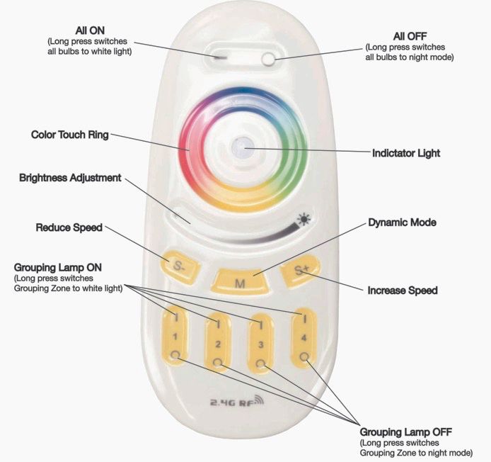
CONTENTS

   General Information                               4

   Limited Warranty (USA Only)                       5

   Safety Guidelines                                 6

   Maintenance Guidelines                            8

   Overview                                          9

   Installation Instructions                         10

   Wireless Remote Functions                         11

   Wireless Remote Range                             14

   Trouble Shooting Tips | FAQs                      16

   Technical Specifications | Dimensional Drawings   17

                                   3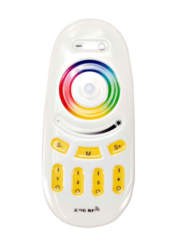
G E N E R A L I N F O R M AT I O N
INTRODUCTION
Please read and understand all instructions in this manual carefully and thoroughly before attempting
to operate this product. These instructions contain important safety and use information.

UNPACKING: This product has been thoroughly tested and has been shipped in perfect condition.
Carefully check the shipping carton for damage that may have occurred during shipping. If the carton
appears to be damaged, carefully inspect your product for damage and be sure all accessories
necessary to assemble the product have arrived intact. In the event damage has been found or parts
are missing, please contact our customer support team for further instructions.
Please do not return this product to your dealer without first contacting customer support at the
number listed below. Please do not discard the shipping carton in the trash. Please recycle whenever
possible.

CUSTOMER SUPPORT
Tel: 800-322-6337 | Fax: 323-582-2941 | www.eliminatorlighting.com | support@eliminatorlighting.com

WARRANTY RETURNS

All returned service items, whether under warranty or not, must be freight pre-paid and accompanied
by a return authorization (R.A.) number. The R.A. number must be clearly written on the outside of the
return package. A brief description of the problem as well as the R.A. number must also be written
down on a piece of paper and included in the shipping container. If the unit is under warranty, you
must provide a copy of your proof of purchase invoice. Items returned without an R.A. number clearly
marked on the outside of the package will be refused and returned at the customer’s expense. You
may obtain an R.A. number by contacting customer support.

                                                  4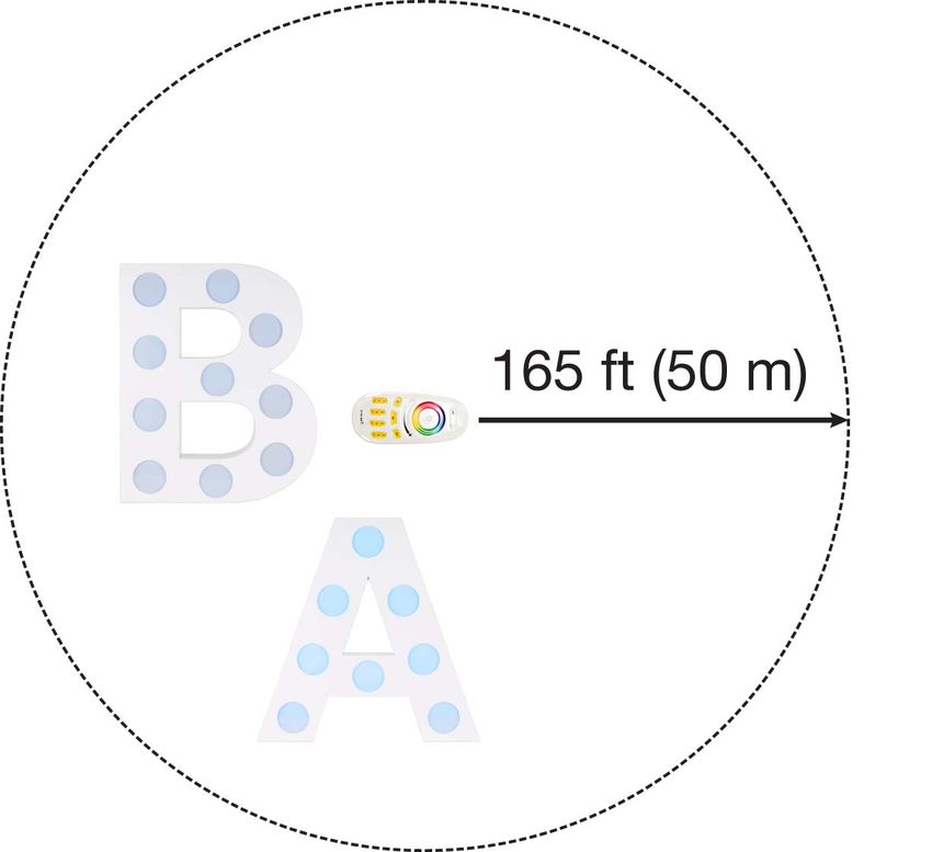
ELIMINATOR LIMITED WARRANTY (USA ONLY)
A. Eliminator Lighting, an ADJ Products, LLC brand, hereby warrants, to the original purchaser, ADJ Products, LLC
products to be free of manufacturing defects in material and workmanship for a prescribed period from the date of
purchase (see specific warranty period listed below). This warranty shall be valid only if the product is purchased within
the United States of America, including possessions and territories. It is the owner’s responsibility to establish the date
and place of purchase by acceptable evidence, at the time service is sought.

B. For warranty service you must obtain a Return Authorization number (RA#) before sending back the product, please
contact ADJ Products, LLC Service Department at 800-322-6337. Send the product only to the ADJ Products, LLC factory.
All shipping charges must be pre-paid. If the requested repairs or service (including parts replacement) are within the terms
of this warranty, ADJ Products, LLC will pay return shipping charges only to a designated point within the United States.
If the entire instrument is sent, it must be shipped in its original package. No accessories should be shipped with the
product. If any accessories are shipped with the product, ADJ Products, LLC shall have no liability whatsoever for loss of
or damage to any such accessories, or for the safe return thereof.

C. This warranty is void if the serial number has been altered or removed; if the product is modified in any manner which
ADJ Products, LLC concludes, after inspection, affects the reliability of the product; if the product has been repaired or
serviced by anyone other than the ADJ Products, LLC factory unless prior written authorization was issued to purchaser
by ADJ Products, LLC; if the product is damaged because not properly maintained as set forth in the instruction manual.

D. This is not a service contract, and this warranty does not include maintenance, cleaning or periodic check-up. During
the period specified above, ADJ Products, LLC will replace defective parts at its expense with new or refurbished parts,
and will absorb all expenses for warranty service and repair labor by reason of defects in material or workmanship. The
sole responsibility of ADJ Products, LLC under this warranty shall be limited to the repair of the product, or replacement
thereof, including parts, at the sole discretion of ADJ Products, LLC. All products covered by this warranty were
manufactured after August 15, 2012, and bear identifying marks to that effect.

E. ADJ Products, LLC reserves the right to make changes in design and/or improvements upon its products without any
obligation to include these changes in any products theretofore manufactured. No warranty, whether expressed or implied,
is given or made with respect to any accessory supplied with products described above. Except to the extent prohibited
by applicable law, all implied warranties made by ADJ Products, LLC in connection with this product, including warranties
of merchantability or fitness, are limited in duration to the warranty period set forth above. And no warranties, whether
expressed or implied, including warranties of merchantability or fitness, shall apply to this product after said period has
expired. The consumer’s and/or Dealer’s sole remedy shall be such repair or replacement as is expressly provided above;
and under no circumstances shall ADJ Products, LLC be liable for any loss or damage, direct or consequential, arising out
of the use of, or inability to use, this product.

This warranty is the only written warranty applicable to Eliminator Lighting, an ADJ Products, LLC brand, and supersedes
all prior warranties and written descriptions of warranty terms and conditions heretofore published.

MANUFACTURER’S LIMITED WARRANTY PERIODS:
All Eliminator Lighting products (except laser diodes) = 1-year (365 days) Limited Warranty (Such as: Special Effect
Lighting, Intelligent Lighting, UV lighting, Strobes, Fog Machines, Bubble Machines, Mirror Balls, Par Cans, Trussing,
Lighting Stands etc., excluding lamps)
Laser Products = 1 Year (365 Days) Limited Warranty (excluding laser diodes which have a 6 month limited warranty)
Batteries = 180 Day Limited Warranty

To register your Eliminator Lighting product online, please click here to the ADJ Warranty Registration Page:
https://www.adj.com/portal/user/register/

                                                             5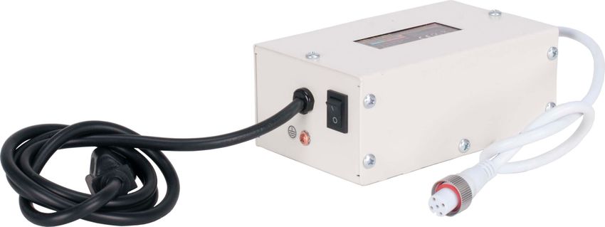
SAFETY GUIDELINES
To guarantee smooth operation, it is important to follow all instructions and guidelines in this manual.
ELIMINATOR LIGHTING is not responsible for injury and/or damages resulting from the misuse of these
devices due to the disregard of the information printed in this manual. Only qualified and/or certified personnel
should perform installation of these devices and only the original rigging parts included with these devices
should be used for installation. Any modifications to these devices and/or the included mounting hardware will
void the original manufacturer’s warranty and increase the risk of damage and/or personal injury.

             THERE ARE NO USER SERVICEABLE PARTS INSIDE THESE DEVICES. DO NOT
             ATTEMPT ANY REPAIRS YOURSELF; DOING SO WILL VOID YOUR
             MANUFACTURER’S WARRANTY. DAMAGES RESULTING FROM MODIFICATIONS TO
             THESE DEVICES AND/OR THE DISREGARD OF SAFETY INSTRUCTIONS AND
             GUIDELINES IN THIS MANUAL VOID THE MANUFACTURER’S WARRANTY AND ARE
             NOT SUBJECT TO ANY WARRANTY CLAIMS AND/OR REPAIRS.

             KEEP FLAMMABLE MATERIALS AWAY FROM THESE DEVICES!
             DO NOT SET UP ON SOFT OR UNEVEN SURFACES.

             UNPLUG DURING LONG PERIODS OF NON-USE.
             ALWAYS DISCONNECT FROM POWER BEFORE PERFORMING MAINTENANCE!
             ALWAYS REPLACE LAMPS AND FUSES WITH REPLACEMENTS OF THE SAME TYPE!

             INDOOR / DRY LOCATIONS USE ONLY!
             DO NOT EXPOSE DEVICES TO RAIN AND/OR MOISTURE!

             SENSITIVE PERSONS MAY SUFFER AN EPILEPTIC SHOCK!

                                                       6
SAFETY GUIDELINES
DO NOT position devices close to any FLAMMABLE MATERIALS while operating.
DO NOT attempt installation and/or operation of devices without knowledge of how to do so.
DO NOT permit operation by persons who are not qualified to operate these types of devices.
DO NOT shake devices, avoid brute force when installing and/or operating.
DO NOT operate these devices if the main power cord has become frayed, crimped and/or damaged.
Replace any damaged power cords with cords of a similar power rating.
DO NOT remove or break off the ground plug from the device power cords.
DO NOT remove or disassemble devices, there are NO user serviceable parts inside.
ALWAYS disconnect devices from main power source before performing any cleaning.
ALWAYS disconnect light from main power source before replacing lights.
ALWAYS be sure to install these devices in an area that will allow proper ventilation.
NEVER remove the ground prong from the power cable.
Power cords should be safely routed and secured so they are not likely to get pinched.
Disconnect power cords during long periods of non-use.
Use the original packaging and materials to transport these devices for service.
These devices should be serviced by qualified service personnel when:
• The power cords or plugs have become damaged.
• Objects have fallen on and/or liquid has spilled into the devices.
• The devices have been exposed to rain and/or moisture.
• The devices do not operate normally or exhibit a marked change in performance.
7MAINTENANCE GUIDELINES
DISCONNECT POWER BEFORE PERFORMING ANY CLEANING OR MAINTENANCE!
CLEANING
Frequent cleaning is recommended to ensure proper function, optimized light output, and an extended
life. The frequency of cleaning depends on the environment which the device operates in: damp,
smoky, or particularly dirty environments can cause greater accumulation of dirt on the devices. Clean
the external surface and the lenses of the lights at least every 20 days with a soft cloth to avoid
dirt/debris accumulation.
NEVER use alcohol, solvents, or ammonia-based cleaners.
MAINTENANCE
Regular inspections are recommended to ensure proper function and extended life. There are no user
serviceable parts inside these devices, please refer all service issues to Eliminator Lighting. Should
you need any spare parts, please order genuine parts from Eliminator Lighting.
Please refer to the following points during routine inspections:
• A detailed review should be performed by an approved electrical engineer every three months,
to make sure the circuit contacts are in good condition and prevent overheating.
• Check for any deformations on the unit. Deformations could allow for dust to enter into the
devices, or cause the devices to fail and seriously injure a person(s).
• Electric power supply cables must not show any damage, material fatigue, or sediments.
8OVERVIEW
Included items:
Power Supply (x1) Remote Control (x1)
24” Illuminated 24” Illuminated 24” Illuminated
Letter “B” (x1) Letter “A” (x1) Letter “R” (x1)
9I N S TA L L AT I O N I N S T R U C T I O N S
FLAMMABLE MATERIAL WARNING
Keep devices minimum 5.0 feet (1.5m) away from flammable materials and/or pyrotechnics.
ELECTRICAL CONNECTIONS
A qualified electrician should be used for all electrical connections and/or installations.
DO NOT INSTALL THE DEVICES IF YOU ARE NOT QUALIFIED TO DO SO!
FOR ADDED PROTECTION, INSTALL DEVICES IN AREAS OUTSIDE WALKING PATHS, SEATING
AREAS, OR AREAS WERE UNAUTHORIZED PERSONNEL CAN REACH THE DEVICES.
DEVICES MUST ALL BE INSTALLED FOLLOWING ALL LOCAL, NATIONAL, AND COUNTRY
COMMERICAL ELECTRICAL AND CONSTRUCTION CODES AND REGULATIONS.
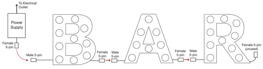
ELECTRICAL CONNECTIONS
Each of the illuminated letters included in the kit features one electrical lead with a 5-pin male
connector and one electrical lead with a 5-pin female connector. The illuminated letters should be
arranged in the proper order, then their electrical leads may be daisy-chained together. The male
connector lead on the first illuminated letter (the letter “B” in the example shown in the diagram below)
should then be connected to the 5-pin female connector on the power supply. Please refer to the
diagram below.
NOTE: THE FEMALE CONNECTOR ON THE LAST LETTER WILL NOT BE USED
10WIRELESS REMOTE FUNCTIONS
The Decor BAR Mini has been pre-programmed to respond to the included remote control as
Grouping/Zone 1. The remote requires (2) AAA batteries (not included). Hold the remote in your hand
so the Color Touch Ring is positioned at the top and the (4) Grouping Lamp ON/OFF buttons are
positioned at the bottom. Before installing, it is recommended to first test the Decor BAR Mini to
confirm the remote control works correctly and there are no issues. After testing, install the Decor
BAR Mini in the desired location following the Installation Instructions in this manual.
11WIRELESS REMOTE FUNCTIONS
[-] ON BUTTON
Powers the device(s) on.
Pressing and holding will turn all the bulbs ON to Warm White mode.
Use the Adjustable Brightness to increase or decrease the brightness intensity.
[o] OFF BUTTON
Powers the device(s) off.
Pressing and holding will turn all the bulbs ON to “Night Mode”.
No Adjustable Brightness is available in this mode.
COLOR TOUCH RING
The display color of the bulbs can be selected using the Color Wheel. Once the color has been set,
the Adjustable Brightness control can be used to increase or decrease the brightness intensity of the
selected color.
BRIGHTNESS ADJUSTMENT
The brightness of the bulbs can be adjusted using the slider control under the Color Tocuh Ring.
[M] DYNAMIC MODE BUTTON
Pressing this button will cycle through the (9) Dynamic Modes programs (see table below).
MODE NO. DYNAMIC MODES BRIGHTNESS SPEED
1 7 Colors Fade
2 White Fade
3 RGBW 4 Colors Fade
4 7 Colors Jump
5 All Colors Jump Adjustable Adjustable
6 Red Fade and Flash
7 Green Fade and Flash
8 Blue Fade and Flash
9 Random Mode
12WIRELESS REMOTE FUNCTIONS
[S] [S+] BUTTONS
These buttons can be used to control the program speed of the selected Dynamic Mode program.
Each press of either of these buttons will decrease or increase the program speed.
[GROUPING-ZONES 1-4] BUTTONS
These ON/OFF buttons allow you to control (4) independent Groups/Zones.
ASSIGNING GROUPING ZONES
You can assign up to (4) individual Groups/Zones to the included remote control.
Groups/Zones can consist of one or more illuminated letters.
INDIVIDUAL GROUPING ZONES
1. Disconnect the illuminated letter(s) from power.
2. Reconnect the illuminated letter(s) to power. Within 3 seconds, press and hold the [ | ] portion of the
desired Grouping Zone Button.
3. The illuminated letter(s) will pulse 3 times to indicate that it has been successfully assigned to the
grouping zone, or it will pulse 8 times to indicate that it has been successfully removed from the grouping
zone.
DELETE ALL GROUPING ZONES
1. Disconnect all illuminated letters that are being controlled by the remote from power.
2. Reconnect the illuminated letters to power. Within 3 seconds, press and hold the [ - ] ON BUTTON at
the top of the remote. The illuminated letters will pulse 8 times to indicate that control from all grouping
zones on the remote has been removed.
NOTE: DUE TO THE SHORT TIME FRAME PERMITTED TO PRESS THE [ - ] ON BUTTON AFTER
POWER HAS BEEN RECONNECTED, IT IS ADVISABLE TO PLUG THE ILLUMINATED LETTERS
INTO A SINGLE SWITCHABLE POWER SOURCE FOR EASE OF CONNECTING AND
DISCONNECTING POWER WHILE SETTING THE GROUPING ZONES.
13WIRELESS REMOTE RANGE
The Wireless Remote has a maximum range of 165 ft (50 meters),
and will affect all Eliminator Decor illuminated letters included in
this kit. Letters purchased separately or as part of another kit may
not respond to the Wireless Remote until they are assigned to one
of the Wireless Remote’s Grouping Zones (see page 13 for
detailed instructions).
Please note that the illuminated letters may also be affected by other wireless devices operating
nearby, and those devices may likewise be affected by the Wireless Remote, regardless of
whether those devices were produced by Eliminator Lighting or by another manufacturer. To
minimize the chances of interference, consider the operating range of both the illuminated letters as
well as any nearby wireless devices and install them so that they are located well outside of each
other’s operating range.
In order to maximize the effective range of the Wireless Remote, please pay attention to the following
points when installing the illuminated letters:
• Ensure that a direct line of sight path exists from the Wireless Remote to the letters, as the
signal from the Wireless Remote cannot travel through walls, around corners, or through
obstacles.
• Ensure that the illuminated letters are positioned so that the unlit side is facing away from the
direction of the Wireless Remote.
14WIRELESS REMOTE RANGE
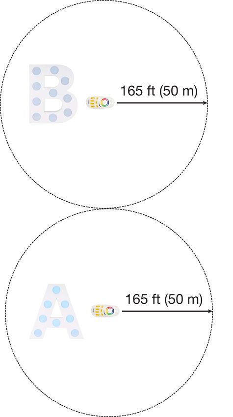
The range of the Wireless Remote can be taken advantage of
to easily configure multiple illuminated letters to the same
display mode. A single Wireless Remote will issue the same
command signal to all letters within range, as long as all the
letters are set to the same Grouping Zone.
When setting multiple groups of illuminated letters to
different display modes, the user may choose to rely on the
minimum separation distance. In this case, the Wireless
Remote(s) being used to set up each display mode should
be located at least 330 feet (100 m) apart in order to
minimize the risk of interference, and each illuminated letter
should be placed within range of the Wireless Remote being
used to configure its desired display mode. Please see the
diagram to the left for reference.
However, due to the long range of the Wireless Remote, it
may be more convenient to utilize the Grouping Zone
function on the Wireless Remote. This allows a single
Wireless Remote to issue different commands to different
groups of illuminated letters without having to take the
minimum separation distance into consideration (see page
13 for detailed instructions).
NOTE: After the illuminated letters have been set up,
they can be moved to a different location as needed. The
illuminated letters will adhere to the previously set
configuration even after they have been moved out of
range of the Wireless Remote.
15TROUBLE SHOOTING TIPS
The device(s) does not turn on.
1. Confirm that the Power Supply is switched on and plugged into an electrical outlet.
2. Find circuit breaker that controls the outlet that the light is plugged into, and check whether it
has been tripped.
3. Confirm that the electrical leads for each device are fully seated and securely connected.
Please note that the female 5-pin connector of the last device in series will be left unused.
4. Confirm that the power cords for the lights and devices are not damaged or cut.
5. Check that the Wireless Remote is operational (see below for details).
6. If none of these solutions work, please contact Eliminator Customer Service.
The device(s) does not respond to the Wireless Remote.
1. Check that the Wireless Remote has batteries, and replace the batteries if necessary.
2. Confirm that the device(s) have been assigned to the Wireless Remote and/or Grouping Zone
that you are attempting to control.
3. Confirm that the device(s) are within the 165-ft (50 meter) maximum operating range of the
Wireless Remote.
4. If none of these solutions work, please contact Eliminator Customer Service.
F R E Q U E N T LY A S K E D Q U E S T I O N S
1. Is there a fuse? Can it be replaced?
No, neither the illuminated letters nor the power supply include a fuse.
2. Does this device have a power switch?
Yes, the main power switch is located on the power supply.
3. Does the last device in series need to have both electrical leads connected?
No, the female 5-pin connector of the last device in series will be left unused and
disconnected.
4. Can the illuminated letters operate on battery power?
No, these devices do not feature battery power and must be plugged into an electrical outlet
during operation.
5. What is the maximum range of the Wireless Remote?
The maximum range is 165 feet, or 50 meters.
16T E C H N I C A L S P E C I F I C AT I O N S
Model: Decor BAR Mini
Light Source: RGBW LEDs
Power Supply: 12VDC ~ 24VDC
Connectors: 5-pin barrel-type
Lens Shape: circular lenses
Control: Battery powered wireless remote control
Wireless Remote Features:
• Color Touch Ring
• Brightness Intensity Adjustment
• Color Macros with Adjustable Speed
• On/Off Switch
• Grouping Zone Capability
Dimensions:
• Letter B: 24.0” (610mm) height x 20.1” (511mm) length x 3.9” (100mm) width
• Letter A: 24.0” (610mm) height x 24.0” (610mm) length x 3.9” (100mm) width
• Letter R: 24.0” (610mm) height x 22.7” (576mm) length x 3.9” (100mm) width
Weight: Letter B: 5.3 lbs (2.4 kg) / Letter A: 4.8 lbs (2.2 kg) / Letter R: 5.4 lbs (2.4 kg)
Specifications subject to change without any prior written notice.
DIMENSIONAL DRAWINGS
NOTE: DIMENSIONS NOT TO SCALE
17You can also read