User manual PCB Controlled Multi Washer Panel with Pneumatic Pump
←
→
Page content transcription
If your browser does not render page correctly, please read the page content below
user manual
PCB Controlled
Multi Washer Panel with
Pneumatic Pump
index
1.OO		overview										page

1.01 Safety Precautions                                 3
1.02 Overview                                           3
1.03 Package Contents                                   4
1.04 Panel Dimensions                                   4

2.OO		             installation

2.01 Preliminary Tasks                                  4
2.02 Panel Mounting                                     4
2.03 Peripheral Elements                                5
2.04 Tubing                                             5
2.05 Electrical Connections                             6

3.OO		programming

3.01 General                                            8
3.02 Unit Parameters                                    8
3.03 Channel Parameters                                 9
3.04 Product Parameters                                 10
3.05 Water Parameters                                   11
3.06 Washer Extractor Parameters                        11
3.07 Formulas                                           13
3.08 On-line View                                       14
3.09 Upload/Download                                    15
3.10 Maintenance                                        15
3.11 Manual Dosage                                      16
3.12 Calibration                                        16

4.OO		operation

4.01 Start-Up                                           17
4.02 Prime Product Delivery Tubes                       17
4.03 Calibrate the Products                             17
4.04 Calibrate the Water                                17
4.05 Check the Dosage                                   17
4.06 Adjust the Flush of each Washing Machine           17
4.07 Start each Washing Machine and Check the Signals   17

5.OO		             service parts										 18

6.OO		warranty

6.01 Limited Warranty                                   20
6.02 Limitation of Liability                            20
1.OO overview
1.O1 Safety Precautions
       WARNING! Please read precautions thoroughly before operation. Meet all applicable local codes and regulations.
                                THANK YOU FOR YOUR INTEREST IN OUR PRODUCTS
                          Please use this equipment carefully and observe all warnings and cautions.
• Both the unit and its peripheral elements must be handled by qualified technical personnel.
• Make sure the installation is carried out according to the current regulations of the state, county and city.
• Do not mount the unit on an irregular or unstable surface.
• This unit is designed to work in a vertical position.
• The unit must be installed in an area with adequate clearance, far from possible impacts, electromagnetic noise sources
  and pipelines of gas, steam or water.
• The top of the cabinet is not a shelf! Do not leave objects on the unit.
• Warranty is voided if the user modifies, adds or suppresses any feature of the unit.
• All components involved in maintenance tasks must be the ones registered in the spare parts list supplied by the
  manufacturer. Otherwise the Warranty is void.
• The installation of the dosing system must be performed according to the instructions of this manual.
• Main electrical power supply must be 110-120VAC, at 60 Hz.
• Always use wires in good condition.
• The water supply to the unit must conform to the specifications of this manual.
• The high pressure air supply to the unit must conform to the specifications of this manual.
• The unit should be configured according to the programming manual.
• All chemical products must be stored in approved container, at a safe distance from the unit.
• The handling of chemical products requires the proper safety measures such as protective glasses, mask and gloves.

1.O2 Overview
PCB controlled pneumatic wall-mount units are designed to dose chemical products to multiple washer extractors. The
maximum number of products that can be used with a single unit is eight (8). Regardless of the number of dosage channels
the maximum number of washers the products can be distributed to by a single unit is six (6).

All the components of the system are consistent with general purpose industry standards, and the materials of construction
are compatible with all normal laundry products.

The measurements made by the built-in flow meter ensure reliable, accurate and repeatable product dosage. The use of a
flow meter also allows for additional safety measures and alarms to prevent mixing of chemicals.

The pneumatic wall-mount units have five major components:
   1) The collection manifold (Mounted on the main panel.)
   2) The dosing channel (From the collection manifold on the main panel out to the distribution manifold.)
   3) The distribution manifold, (Mounted separately.)
   4) The calibration vase. (Mounted separately.)
   5) The communications boxes (To capture and transmit the signals from each washer extractor to the controller.)

When a qualified signal is detected by the communication box, the unit will dose the appropriate products according to the
settings of the formula and washing phase being executed.

                                                                                                                             3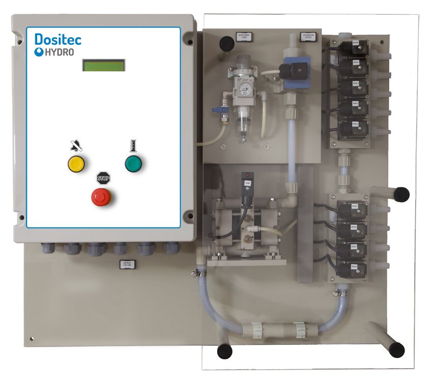
1.OO overview
    1.O3 Package Contents
    PCB Controlled Multi Washer Panel with Pneumatic Pump

     HYDSPD0083           PCB, 8P, 4WE, 1CH, NEU, V, USA

     HYDSPD0084           PCB, 8P, 6WE, 1CH, NEU, V, USA

     HYDSPD0083M          PCB, 8P, 4WE, 1CH, NEU, V, MET

     HYDSPD0084M          PCB, 8P, 6WE, 1CH, NEU, V, MET

    A key feature to the system is delivering up to 8 chemicals
    to up to 6 washers with a single, durable, pneumatic,
    double-diaphragm pump.

    Aiding in the reliability and longevity of the system is a
    water flush that cleans the entire channel after every
    product delivery.

    The collection manifold, both sides of the pump, the flow
    meter, and all the way through the distribution manifold to
    the washer is flushed with water, to prevent the effects of
    long-term chemical exposure.

    1.O4 Panel Dimensions
     Panel Height: 24.8 in (630 mm)
     Panel Width: 27.6 in (700 mm)
     Panel Depth: 7.9 in (200 mm)

                                                                          24.8”

                                                                  27.6”           7.9”

4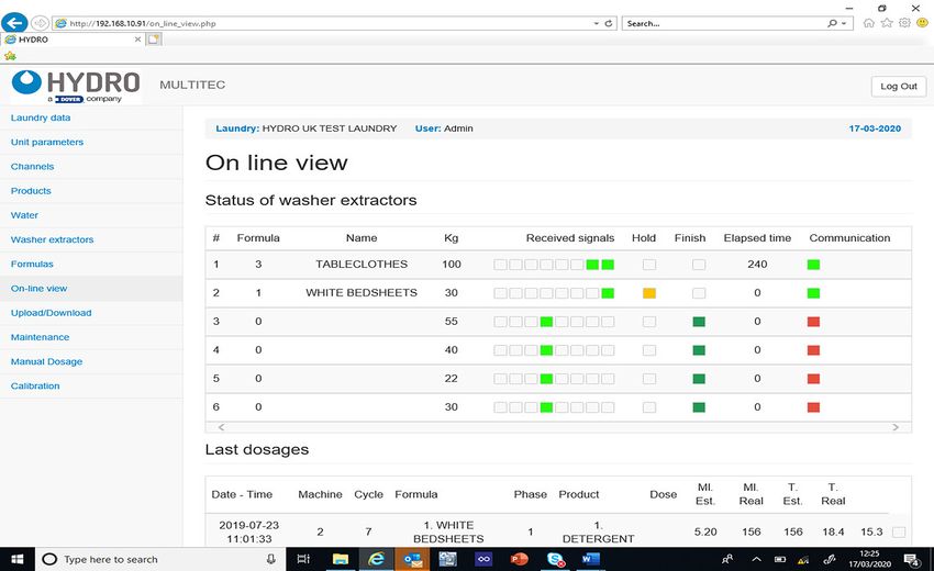
2.OO installation
    2.O1 Preliminary Tasks

    It is highly recommended to visit the site well before installation, to familiarize yourself with the physical layout of the laundry,
    the machines present and their characteristics, the laundry products in use, and how any current laundry dosing system is
    being employed.

    Pay attention to the entire laundry system, its requirements and its schedules, to ensure a smooth transition to, and
    installation of, your Dositec laundry dosing system.

    Learn the operations of all the washers, as well as the products they use, and why. Determine the capacities of the machines
    and what is involved in programming their signals.

    Measure the distance between where the Dositec main panel will be installed and the location of the Distribution Manifold(s).

    Determine where the communication boxes will be installed for each washer, as well as the lengths of 4-conductor cable
    needed to daisy-chain them back to the main panel, and the lengths of 10-conductor cable from each communication box to
    each washer’s signal terminals.

    Identify the voltage each washer is using for it’s signals. Determine how many conductors you need for connecting the main
    panel and the distribution manifold(s) and the distance for that connection.

    Measure the lengths of chemical delivery hose that will be needed to run from the main panel to the distribution manifold(s),
    from the distribution manifold(s) to the washers, and back to the Calibration vase.

    Identify how the hoses will be routed, and what hardware will be required to accomplish that scheme.

    Identify where the bulk chemicals will be placed and the lengths of hose needed to connect them to the Collection Manifold of
    the main panel.

    Calculate how many hose clamps will be necessary to complete the installation.

    It is recommended to order the specific installation kit for the system being installed, which is available from Hydro Systems. If
    the mounting hardware is obtained from local providers, all items should be the same as the ones listed in the kit.

    Schedule an orderly transition from any previous dosing system in use, and investigate if any portions of that system must
    be removed before the installation of the Dositec system. In case a previous unit is already working in the site, all the existing
    elements must never interfere with the new installation.

    2.O2 Panel Mounting
    • In order to make the unit work correctly, it must be
      placed on a clear and flat wall.

    • The system must be placed at such a height that the
      screen must be easily manipulated.

    • The panel’s mounting dimensions are approximately
      23.6 in by 26.4 in (600 mm by 670 mm), but may vary                    23.6”
      slightly, so use the actual panel being installed as a
      template. To use the supplied mounting hardware, drill
      four 5/16 in (8 mm) holes at the locations indicated.

    • Insert the included fittings.

    • Place the unit on the wall and use the included screws
      and mounting hardware to hang the system.
                                                                                                     26.4”
                                                                                 Note: Indicated Measurements are Approximate!

5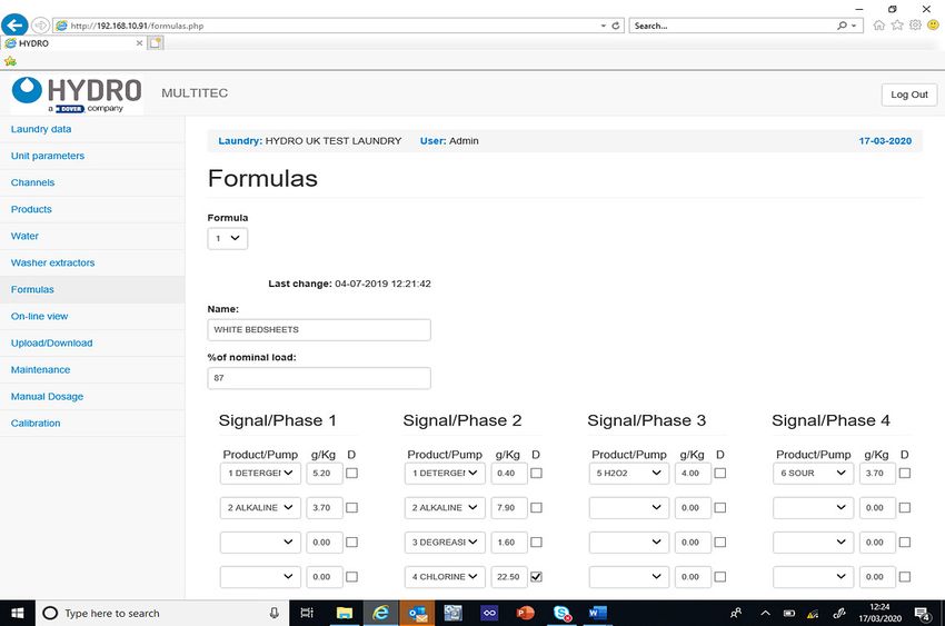
2.OO installation (continued)
2.O3 Peripheral Elements
After placing the unit, it is necessary to mount the rest of the elements:

Distributor: This element is the responsible for diverting the products to the corresponding washer extractor. Only one
machine is attended while the others are queued. It is recommended to set the distributor at a position equidistant from the
washer extractors.

Calibration Vase: Since this vase is used for dosage calibration, it should be installed on the wall near the main panel.
Please note the vase is connected by a hose to the distribution manifold. Make provision for draining the calibration vase and
for overflow from the vent fitting.

Communication Boxes (machine signal interfaces): These elements are used to get the signals from the machines so they
can be acquired by the unit. There must be one box per washer extractor. The recommended position is a clear place on the
wall behind every machine.
                                                                                                                    to Distributor
2.O4 Tubing
                                                                                                                1/2” Tubing
Once all elements are on the wall, their fittings must be                                                      (Water valve is
connected with the tubes. We recommend to use 1/2 inch                                                          always first.)
reinforced tubing.

Water Inlet: Make sure there is enough water supply for
the unit: 20 PSI or 1.5 bar in dynamic range.

If this is not possible, it is mandatory to install a Pressure
Control to achieve this condition.

                                                                                                                                 Water
                                                                                                                                 Inlet

Chemical Pickup: Decide the best distribution for the
                                                                                                                    to Distributor
tanks / drums of product.
                                                                                                      Valves
After that, connect all tubes from the inlets at the unit’s                                           W
manifold to the suction lances.                                                                       2              P1
                                                                                                      3        P2
            Inlet Valve 1   =   Water Inlet                                                           4        P3
            Inlet Valve 2   =   Product 1
            Inlet Valve 3   =   Product 2                                                             5        P4     Products
            Inlet Valve 4   =   Product 3                                                             6        P5     (1/2” Tubing)
            Inlet Valve 5   =   Product 4                                                             7        P6
                                                                                                      8        P7
            Inlet Valve 6   =   Product 5                                                             9        P8
            Inlet Valve 7   =   Product 6
            Inlet Valve 8   =   Product 7
            Inlet Valve 9   =   Product 8

                                                                                                 Chemical Drum

Distributor Tubing: Install the delivery tubing from the                                 Valves
main panel to the distributor inlet and connect each
distributor delivery tube to the appropriate washer, as                              1   2   3    4   5   6

shown to the right.                                                                                            Delivery from
                                                                                                                Main Panel
         Distributor Valve 1     =   Machine 1
         Distributor Valve 2     =   Machine 2
                                                                                         M
                                                                                         M chin
                                                                                         M chin 2
                                                                                         M hin 3
                                                                                         M chin 4

         Distributor Valve 3     =   Machine 3
                                                                                           a
                                                                                           a e
                                                                                           ac e
                                                                                           a e
                                                                                           ac e
                                                                                             hi 5

         Distributor Valve 4     =   Machine 4
                                                                                               ne
                                                                                                  6

         Distributor Valve 5     =   Machine 5                           Machine 1
         Distributor Valve 6     =   Machine 6
                                                                                                                                         6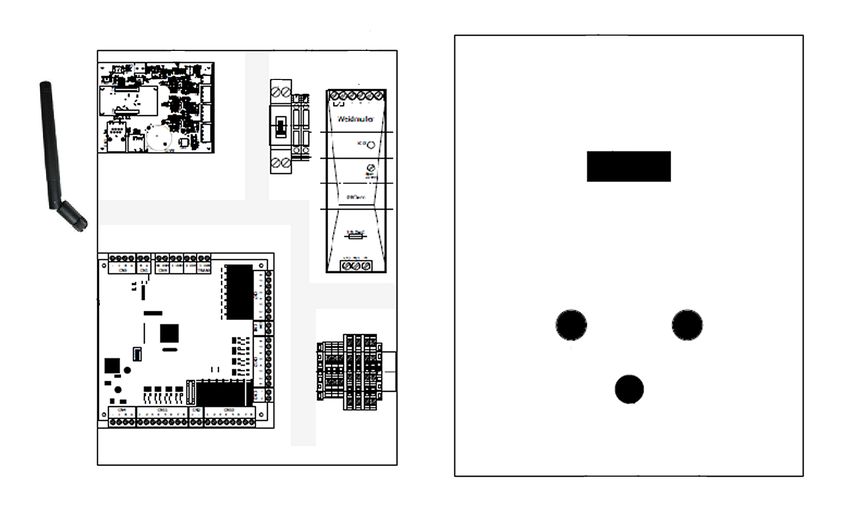
2.OO installation (continued)
    2.O4 Tubing (continued)                                                                                    Set air pressure regulator
                                                                                                                  to 60 PSI or 4 bar
    Pressurized Air Connection: Make sure their is sufficient
    air pressure (more than 60 PSI or 4 bar).

    Remember the main air inlet tubing is 8 mm.

    Once the main inlet is connected to the unit, set the
    regulator to 60 PSI or 4 bar.

                                                                                                Bring
                                                                                           pressurized air
                                                                                            into cabinet,
                                                                                           more than 60
    2.O5 Electrical Connections                                                             PSI or 4 bar

    Main Input Power: Connect a 110 to 230 VAC source to
    the X1 connections in the cabinet.
    Remember never to get the power from a washer extractor.
    An independent 10 amp breaker is recommended.
    The power cable must be constructed of 3 wires with at
                                                                                                       Recommended
    least 1.5 mm cross-section.
                                                                                                       power cord
    • Line/Phase (black) goes to the ‘L’ connector.                                                    routing
    • Neutral (white) goes to the ‘N’ connector.
    • Ground (green) goes to the ‘Ground’ connector.                                                           Main Input Power
    Once the power is supplied to the unit, all inputs, outputs                                                (110 to 230 VAC)
    and communications may be configured.

    Distributor Connections: Follow the wiring diagrams to below, when making the electrical connections between the main
    panel and the distributor control cabinet

                                                                                   C   1   2   3   4   5   6

                                                  PCB
                                                                      1 = Distributor Valve 1 for Washer 1
               Recommended                                            2 = Distributor Valve 2 for Washer 2
               Distributor cable                                      3 = Distributor Valve 3 for Washer 3
                                                                                                                                             Distributor
               routing                                                4 = Distributor Valve 4 for Washer 4                                   Control
                                                                      5 = Distributor Valve 5 for Washer 5                    1 2 3 4 5 6C
                                                                                                                                             Cabinet
                                                                      6 = Distributor Valve 6 for Washer 6
               Use the indicated terminal blocks                      C = Common connection for all valves

                                                                                                                              OR
    External Alarm Annunciator Connection: The contact                                             +
    at A06 provides 24 VDC at up to 2 amps, to power an
    external alarm signaling device, like a bell, strobe or buzzer.                                -
    Make the positive DC connection to A06, and the negative                                                                  OR
                                                                                    24 VDC
    DC connection to the contact M, as shown to the right.
                                                                                     up to
                                                                                    2 amps

    Electric Water Valve: The positive connection gets power                                                                  Electric
    from the “FL” contact on terminal block CN10, and the                                                                      Water
    negative connection is grounded at terminal block X50.                                                                     Valve

7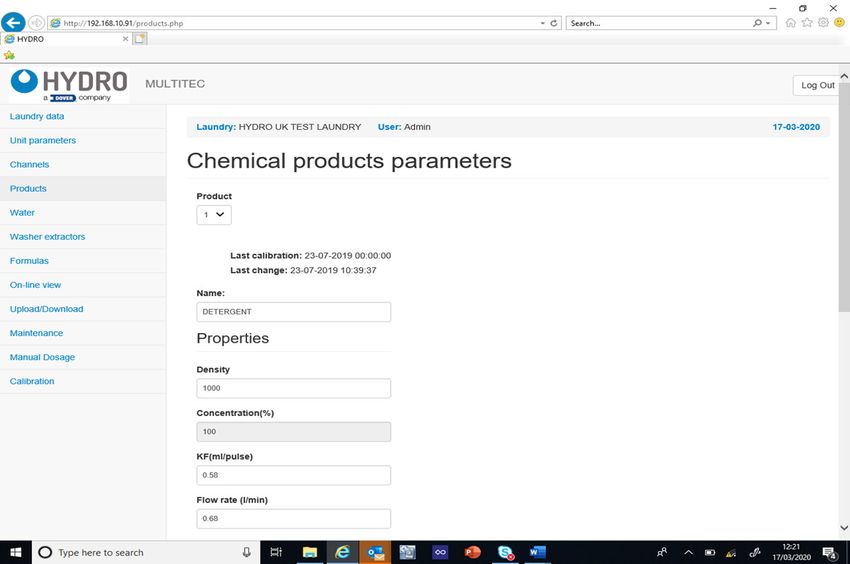
2.OO installation (continued)
2.O5 Electrical Connections (continued)
Be sure the unit is turned off, unpowered, before connecting the communication boxes!
Communication Boxes: Bring the four conductor cable from the first Comm Box into the Main Panel cabinet, and connect
the four wires to the contacts at Terminal Block CN4, as shown below.
Box Identification DIP Switch Settings
If there are Formula Selector boxes in use, their DIP Switch Notice the Formula =1 =3 =5 =7 =9
must be set to the same ID as the Comm Box. Select boxes have =2 =4 =6 =8 = 10
the same ID as their
Communications Box. Box 1 Box 2
CN4
PCB - + B A
Recommended Every Box
Connection
Comm Box cable (top down)
routing port Brown
Yellow
Green Out In Out In
White
Use the indicated terminal blocks Other
Boxes
(If any)
Machine Signals: The signal wires from each washer
connect to their Dositec Communications Box using the
row of connectors at the lower edge of the circuit board,
with the grounds jumpered to have a common connection, Washer Installer
Signal
as shown to the right. Wires
supplied wiring,
1 2 3 4 5 6 7 8 color will vary!
DIP Switch 5 - Auto-Formula Select Time: On the
DIP switch that identifies the Communications Box (see 5 = Off
above), the fifth DIP switch is used to adjust the time period AFS time is
for Auto-Formula Select (AFS). With switch 5 in the Off 5 sec.
position, 5 seconds is the AFS time, so an AFS signal of 5 = On
15 seconds would select Formula 3. With switch 5 in the AFS time is
3 sec.
On position, 3 seconds is the AFS time, so an AFS signal
of 9 seconds would select Formula 3.
CN11 CN2
Product Level Probes: Use the connections “L1” through L1 L2
1 2 3 4 5 6 7 8
L3 L4 L5 L6 L7 L8 +
9
-
“L8” on Terminal Block CN11 to connect as many as eight
(8) product level-sensor lances, so the controller can detect
when a product level is getting low in the chemical drum. 1 2 3 4 5 6 7 8 C
All the probes can use a common power wire connected to
the positive contact of terminal block CN2.
Product 01
Product 02
Product 03
Product 04
Product 05
Product 06
Product 07
Product 08
The diagram to the right shows a junction box being
employed to simplify the wiring and possible maintenance.
(E00) (E01) (E02) (E03) (E04) (E05) (E06) (E07)
Internet Connection: The controller has an Ethernet port
for communicating across networks and over the Internet.
• Cell Modem Connection: If a strong signal is available
near the laundry room, you can connect the Dositec
PLC to a cellular modem, to create a connection to the
Internet. A monthly data subscription is required.
8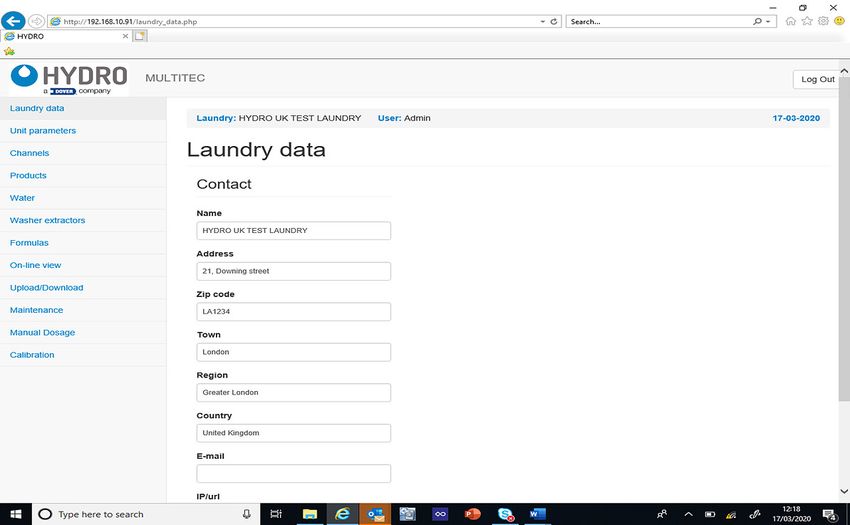
3.OO programming
    Programming the PCB controlled Dositec Laundry Dispensers consists of “Creating a Program Settings File”. Follow the
    steps detailed below to create a program settings file that contains the settings you desire.

    3.O1 General
    1) From a laptop or smartphone connect to the unit WIFI by connecting to multitec_6_ xxxx.
      • Enter Password; dositecsistemas

    2) Open up a web browser and insert IP 192.168.10.91 in the search bar and this will be diverted to the main page.
      • Insert email admin@multitec.com
      • Password 1111

                                                       General Laundry Settings
    3) Enter the laundry details, it is essential to add a contact name and email address.

    4) When all details have been entered click Save at the bottom of the page.

    3.O2 Unit Parameters
    1) Click on Unit parameters in the left-hand column, the below page will open.

                                                            Unit Parameters
9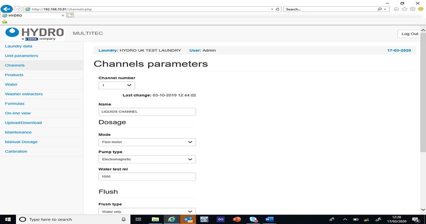
3.OO programming (continued)
3.O2 Unit Parameters (continued)
2) Name – enter the name you wish to give the unit.

3) Enter machine type – Multitec 6.

4) Range
  • Washer extractors – the amount of washer extractors you are connecting the unit to.
  • Products in channel 1 – the number of chemical products you are connecting to the channel.
  • Products in channel 2 – the number of chemical products you are connecting to the channel.

5) When all values have been entered click on Save at the bottom of the page.

3.O3 Channels Parameters
1) Click on Channels in the left-hand column, the below page will open.

                                                        Unit Parameters
2) Channel number – choose the channel you wish to program 1 or 2.

3) Name – name the channel.

4) Mode – choose from the following; time, flow sensor or flow meter. Recommended; flow meter.

5) Pump type – Electromagnetic or pneumatic, dependent on which type is installed on the unit.

6) Water test – amount of water required to create the test within the channel in ml.

7) Flush
   • Flush type – None (direct) or water only (Air flush currently unavailable).
   • Water flush only; use this setting if all chemicals are being pushed to their destination by water only.
   • Direct flush; use this setting if no flush is required to take the products to the inlet and you are pumping them to their
      destination, this must always be used with very high viscous products i.e. Starch when only one product must be
      used in the channel. * It is important to remark that direct flush can only be used when there is only one product in the
      channel (whatever the product is).
8) Alarms
   • Skipped alarms – the amount of alarms that the unit will accept before the alarm buzzer Initiates on the unit and stops
      dosages. Start at 1 and then change to 3 after initial commissioning.
   • Tolerance % - recommended 30%, allows extra theoretical time to obtain the correct amount of pulses given by the flow
      meter when delivering the flush.
9) Click on Save at the bottom of the page.
                                                                                                                             10
3.OO programming (continued)
3.O4 Product Parameters
1) Click on Products in the left-hand column, the below page will open.
Product Parameters
2) Product – choose the valve number you want to program i.e. 1. Remember the product order starts with the valve next to
the water one.
3) Name – enter the name of the product.
4) Properties:
• Density – enter the density of the product, this can be obtained from your chemist. (grams / litre).
• Concentration – enter the concentration of the product. (Always 100% unless the product is a stock solution or the
dosages are referred to the raw material only).
• K/F (mls/pulse) –performing calibration will set this.
• Flow rate (L per min) – performing calibration will set this.
5) Dosage:
• Priority- this must be set for each chemical, if “0” the chemical will not dispense.
• Priority must be set higher for the products in the shortest stage of the wash program e.g.
• Softener should be set at 1-2.
• Priority determines the next machine in the queue to receive the dosage depending on the product it is asking for.
• Mode –time or flow meter, recommended flow meter. Time mode inhibits the product dosage alarms. It should only be
used if the product is extremely viscous or the flow meter is damaged.
• Estate – Liquid or stock solution.
8) Alarms:
• Skipped alarms – start up at 1 and then change to 3 once start-up has been completed, this is the amount of times the
unit can receive an error before it alarms. If an error is received and then the next dosage is correct the skipped alarm
will default back to 0.
• Tolerance % - recommended 30% but may be higher, allows extra theoretical time to obtain the correct amount of
pulses given by the flow meter when delivering the chemical. Note* viscous products require a higher tolerance, more
time must be added not ml.
• Level contact - depends on the suction lance, normally open/normally closed
9) Click on Save at the bottom of the page.
113.OO programming (continued)
3.O5 Water Parameters
1) Click on Water in the left-hand column, the below page will open.
Water Parameters
2) Channel number – dependent on how many channels the unit has, if more than 1 select other numbers to check and save
parameters.
3) Properties:
• KF (ml/pulse) mls of water per pulse recorded by the flow meter when calibrated
• Flow rate – (l/min) litres per min of water passing through the flow meter, recorded when water is calibrated.
4) Click on Save at the bottom of the page.
3.O6 Washer Extractor Parameters
1) Click on Washer Extractors in the left-hand column, the below page will open.
Washer Extractor Parameters
2) Number - the number assigned to the washer extractor.
3) Name – name of the washer extractor i.e. Girbau
3) Properties:
• Kg – Enter the wash capacity of the machine in Kg.
123.OO programming (continued)
3.O6 Washer Extractor Parameters (continued)
3) Properties: (continued)
• Kg – Enter the wash capacity of the machine in Kg.
• Kg sel – yes or no, this is dependent on whether you have installed a selector to manually change the % wash weight
on the unit.
• Flush L – the amount of water in litres required to deliver the chemicals to the washer extractor inlet by means of water
flush.
4) Signal times:
• Acceptance – Length of time in seconds required for the machine to accept a signals.
• Non repetition – time in seconds that the unit will not accept a further signal after the prior signal within that particular
wash stage.
• Lock after end – only on formula selector mode. Time duration after whole dosing process that the unit will accept no
further signals.
5) Washing process:
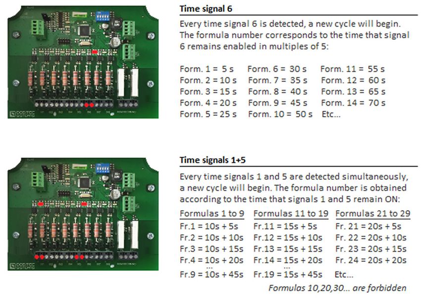
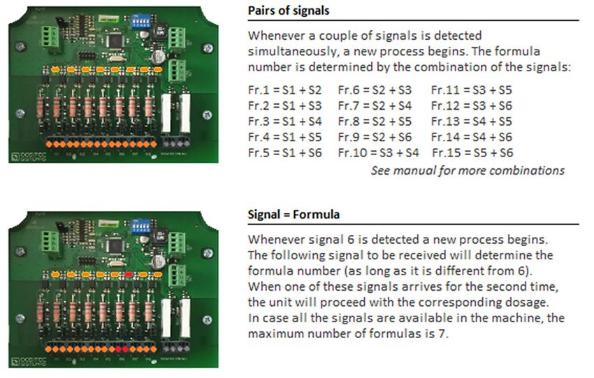
• Formula ID – mode in which the identification of a new washing process is determined, how the machine triggers the
unit to auto select a formula, see below:
(continued)
133.OO programming (continued)
3.O6 Washer Extractor Parameters (continued)
5) Washing process: (continued)
6) Trigger mode – Sequential, Signal + 1st Phase, sequential + 1st phase or signal + repetition.
7) Finish mode – signal or pump. Choose whether you want the unit to end the program via a pump or signal (signal number,
i.e. final rinse, door lock etc).
8) Default formula after finish – choose a formula number for the unit to reset to after finish (0 will create the unit to not select a
formula).
9) Hold machine
• Activation – choose from Not used if no machine hold is present, while queued (whilst waiting for dosage) or while
queued/ during dosage.
• Delay – the Time the unit waits before activating the hold order. Commonly used to let the washer extractor gain some
level of water.
• Timeout – max amount of time before the delay times out.
10) Click on Save at the bottom of the page.
3.O7 Formulas
1) Click on Formulas in the left-hand column, the page shown at the top of the next page will open.
2) Formulas
• Formula – the number of the formula you want to program.
• Last change – this shows the date the formula was last edited.
• Name – the name of formula i.e. white bedsheets.
• % of nominal load - % of load the unit will dispense chemical for.
3) Signal/phase
• Product/pump - enter the product i.e. detergent.
• g/kg – enter the amount you wish you dispense in grams per kilogram.
• D – tick this box to add a delay.
• Delay 1 – the time in which the whole phase is on hold before dosing any products (commonly used to allow the machine
to achieve a water level in the drum when the signal is activated from a fill valve).
• Delay 2 – takes place after delay 1 has expired and will only be applied to products that have been activated with a tick.
The full sequence of leak test, water test, etc, will be applied before any dosing is achieved, even if a 1 second delay is set.
143.OO programming (continued)
3.O7 Formulas (continued)
Formula Settings
4) Repeat the above steps for each signal/phase that chemical is to be added.
5) Click on Save at the bottom of the page.
3.O8 On-line View
1) Click on On-line View in the left-hand column, the page shown below will open.
On-line View
2) From the windows displayed in the on-line view you will be able to the status of the machines, which programs are running
and what signals have been received.
You will also be able to see if the machines are on hold, the amount of chemical dosed, downtime and if alarms have been
received.
153.OO programming (continued)
3.O9 Upload/Download
1) Click on Upload/Download in the left-hand column, the below page will open.
Upload/Download
2) From this screen you can upload the settings you have entered within the MT6 program on your computer/tablet etc or
download from the unit.
3) Click on Save at the bottom of the page.
3.1O Maintenance
1) Click on Maintenance in the left-hand column, the below page will open.
Maintenance Settings
2) IP – Not used (This setting is only used with the Hydro Connect Real-Time Modules [aka RTMs].)
3) Language – the language you require the unit to display.
4) Units system – choose between Metric (EMEA) or US (Americas)
5) Click on Save at the bottom of the page.
163.OO programming (continued)
3.11 Manual Dosage
1) Click on Manual Dosage in the left-hand column, the below page will open.
Manual Dosage Settings
2) From this page you can enter the desired product, dosage, machine and whether you want flush to create a manual
dosage.
3) Clicking on Start will begin the dosage.
3.12 Calibration
1) Click on Calibration in the left-hand column, the below page will open.
Calibration Settings
2) Type – choose whether you want to calibrate a product or water.
3) Product/channel – select the product you want to calibrate or the channel for water.
4) Destination machine – choose which machine you want to calibrate to at the point of inlet. Although currently you must
choose a washer extractor, a 3-way valve can be installed to make the physical calibration easier. (Note: Calibration Vase is
an option to be available in the future.)
5) Click on validate parameters to obtain KF value and Flow rate. (CAUTION! ALWAYS press “Validate Parameters” before
pressing the calibration button, even if you want to re-calibrate after having cleaned the channel, without entered a real
volume.)
6) Insert real obtained volume and save.
174.OO operation
4.O1 Start-Up
After having installed the unit, carry out the start-up by following the steps below.
Previous requirement and unit configuration
Make sure that the laundry is created in Hydro Connect and the equipment is registered in it. In this way the obtaining of
statistical data will be enabled. Start the equipment through the side switch. The service pilot lamp should light up.
Equipment without Internet connection
It will be necessary to have downloaded Hydro Connect users, configuration and formulas files. Connect to the Wi-Fi network
of the device identified as MULTITEC_3_xxxxx. You will find it on the side label of the team. Access the Web Server and
transfer the files. (See Web Server manual for more details.)
Equipment with Internet connection
In this case, the previous transfer of files is not necessary. After about 5 minutes from power-up, the equipment will download
the necessary information for its configuration. Connect to the Wi-Fi network of the device identified as MULTITEC_3_xxxxx.
You will find it on the side label of the team. Access the Web Server. See Web Server manual for more details.)
4.O2 Prime Product Delivery Tubes
All the outlet pipes must be filled with water. To do this you can access the calibration screen and select ‘Water’ at the
calibration mode. After checking that there are no leaks, you can continue with the start-up.
Prime the suction tubes of each product
You have to fill each tube that goes from the suction rod to the pumps using the calibration screen as in the previous step.
In this case, you will select ‘Product’ as the calibration mode. After priming each tube, the channel must be cleaned. It is
important to take into account the chemical incompatibilities when choosing the order of the products to be primed.
4.O3 Calibrate the products
You must keep ‘Product’ on the calibration screen. As in the previous step, you will select each product and press the
calibration button sending the dosage to a washing machine. After the acquisition of the sample, you have to insert the
volume dispensed in milliliters on the screen.
4.O4 Calibrate the water.
The water must be calibrated to the furthest washing machine.
4.O5 Check the dosage
To be sure that the meter works correctly, you can perform manual dosages and take a sample. The amount obtained must
be the same as the estimated amount that appears on the screen.
The manual dosages have to be done without the flush, which involves doing a channel cleaning.
4.O6 Adjust the flush of each washing machine
The user has to execute manual dosages to each washing machine. It is advisable to choose a product with a visible color.
Looking at the entrance of the washing machine, you can know if the configured flush is enough to send the product inside. If
you want to modify the water flush, you can go to the washing machine configuration screen to do it.
4.O7 Start each washing machine and check signals
If the signals of the washing machines are connected correctly, you will activate them one by one to verify the signal reception.
The formula number and the corresponding phases must be seen on the ‘View washing machines’ screen.
185.OO service parts
2 3 General Orientation
1
Key Description
1 PCB Control Cabinet
2 Air Pressure Regulator
4
3 Flow Meter
4 Pneumatic Valves
5
5 Pneumatic Pump
6.1
6 Air Pressure Regulator
Key Part No. Description
6 HYD4810ACQ2W063 Assembly, Air Pressure Regulator
6.5
6.2
6.1 HYD48101662722 Regulator/Filter/Gauge, 1/4”, manual purge
6.2 HYD48101120622 Elbow Air Fitting 1/4 “T6
6.3 HYD4810KQ2H0602AS Straight connector for air 1/4”-T6
6.4 HYD2953216559 Ball valve 3097 MH 1/4”
6.4
6.5 HYD4810221414U Conic brass elbow M/F 1/4”
6.3
9
7
Cabinet Assemblies
8
Key Part No. Description
Inside Outside
7 HYD2721ANT001 Wi-Fi external antenna 2.4 GHz with cable, SMA RP Female B/H
8 HYD1161M6P1EV I/O Board for Laundrytec Micro Controller
9 HYD1161M6P1DV Display Board for Laundrytec Micro Controller (inside cabinet door)
195.OO service parts (continued)
10 Flow Meter
Key Part No. Description
11
10 HYD021713020002 Flow meter 8030, 24VDC, PNP
12 11 HYD54808400299 PVDF, Output Hose Barb, 1/2”
13 12 HYD02171432300 PP Turbine + FPM joints for S030 flux sensor
13 HYD0217297301490 Flow Meter Fitting PP + Turbine
14 HYD1318100FG4812PP Straight connector, S1A PP, T10/12 G1/2” H
14
16
15
Valve Blocks
17 Key Part No. Description
15 HYD0217297301140 3-Valve Block, Ev Type 124, PP (not shown)
HYD0217297301141 4-Valve Block, Ev Type 124, PP
18
HYD0217297301142 5-Valve Block, Ev Type 124, PP
16 HYD54818400238 PVDF cap, 3/8” with VITON O-Ring
17 HYD54818400298 PVDF Barb Fitting 3/8”xT13 w/ O-Ring
18 HYD1318MG4838PP Straight connector, S1A PP, T10/12 G3/8” M
20 Pneumatic Pump
Key Part No. Description
19
19 HYD111310P7 Duotek Pneumatic pump AF 0007, 1/4”G
20 HYD4810SS5Y5Q2W514 5-way control valve for Duotek pump
21 HYD1318G4814PP Elbow fitting, PP, G1/4 M, 10x12
21
206.OO warranty
6.O1 Limited Warranty
Seller warrants solely to Buyer the Products will be free from defects in material and workmanship under normal use and
service for a period of one year from the date of completion of manufacture. This limited warranty does not apply to (a) hoses;
(b) and products that have a normal life shorter than one year; or (c) failure in performance or damage caused by chemicals,
abrasive materials, corrosion, lightning, improper voltage supply, physical abuse, mishandling or misapplication. In the event
the Products are altered or repaired by Buyer without Seller’s prior written approval, all warranties will be void.
No other warranty, oral, express or implied, including any warranty of merchantability or fitness for any particular
purpose, is made for these products, and all other warranties are hereby expressly excluded.
Seller’s sole obligation under this warranty will be, at Seller’s option, to repair or replace F.O.B. Seller’s facility in Cincinnati,
Ohio any Products found to be other than as warranted.
6.O2 Limitation of Liability
Seller’s warranty obligations and Buyer’s remedies are solely and exclusively as stated herein. Seller shall have no other
liability, direct or indirect, of any kind, including liability for special, incidental, or consequential damages or for any other claims
for damage or loss resulting from any cause whatsoever, whether based on negligence, strict liability, breach of contract or
breach of warranty.
Hydro Systems Phone 513.271.88OO
3798 Round Bottom Road Toll Free 8OO.543.7184
Cincinnati, OH 45244 Fax 513.271.O16O
Web hydrosystemsco.com
HYD90100072 Rev D 06/21
21You can also read