UT Austin Villa 2012: Standard Platform League World Champions
←
→
Page content transcription
If your browser does not render page correctly, please read the page content below
In Proceedings of the RoboCup International Symposium 2012 (Robocup 2012),
Mexico City, Mexico, June 2012.
UT Austin Villa 2012:
Standard Platform League World Champions
Samuel Barrett, Katie Genter, Yuchen He, Todd Hester, Piyush Khandelwal,
Jacob Menashe, and Peter Stone
Department of Computer Science
The University of Texas at Austin
{sbarrett, katie, hychyc07, todd, piyushk, jmenashe, pstone}@cs.utexas.edu
http://www.cs.utexas.edu/~AustinVilla
Abstract. In 2012, UT Austin Villa claimed Standard Platform League
championships at both the US Open and RoboCup 2012 in Mexico City.
This paper describes the key contributions that led to the team’s victo-
ries. First, UT Austin Villa’s code base was developed on a solid founda-
tion with a flexible architecture that enables easy testing and debugging
of code. Next, the vision code was updated this year to take advantage
of the dual cameras and better processor of the new V4 Nao robots.
To improve localization, a custom localization simulator allowed us to
implement and test a full team solution to the challenge of both goals
being the same color. The 2012 team made use of Northern Bites’ port
of B-Human’s walk engine, combined with novel kicks from the walk. Fi-
nally, new behaviors and strategies take advantage of opportunities for
the robot to take time to setup for a long kick, but kick very quickly when
opponent robots are nearby. The combination of these contributions led
to the team’s victories in 2012.
Keywords: RoboCup, Nao, SPL, UT Austin Villa
1 Introduction
RoboCup, or the Robot Soccer World Cup, is an international research initiative
designed to advance the fields of robotics and artificial intelligence, using the
game of soccer as a substrate challenge domain. The long-term goal of RoboCup
is to build a team of 11 humanoid robot soccer players that can beat the best
human soccer team on a real soccer field by the year 2050 [7].
RoboCup is organized into several leagues, including both simulation leagues
and leagues that compete with physical robots. This report describes the cham-
pionship team in the Standard Platform League (SPL)1 . All teams in the SPL
compete with identical robots, making it essentially a software competition. All
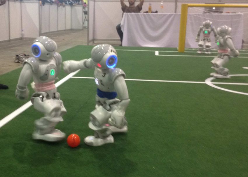
teams use Aldebaran Nao humanoid robots2 , shown in Figure 1.
UT Austin Villa has competed in the Standard Platform League with the Nao
robots every year since the Nao was introduced in 2008. Through these years, we
have built a substantial code infrastructure for robot soccer that served as the
1
http://www.tzi.de/spl/
2
http://www.aldebaran.com/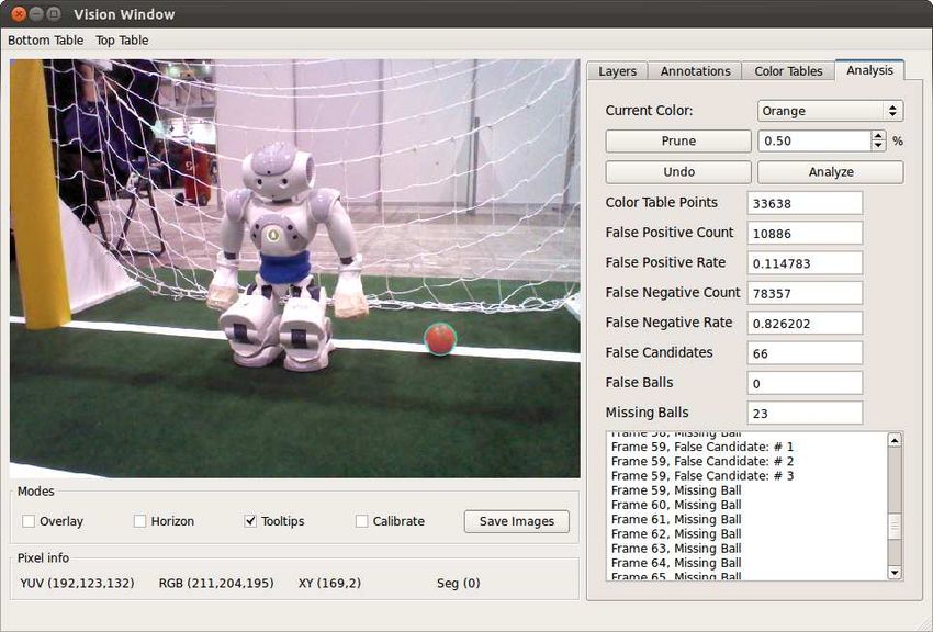
2 UT Austin Villa 2012
Fig. 1. UT Austin Villa’s Aldebaran Nao robots (in pink) competing at RoboCup 2012.
base for our championship in 2012 [1, 2, 4, 5]. This paper describes the team’s key
components, including its software architecture, stream-lined vision processing,
localization for a field with same-colored goals, quick kicks from the walk engine,
and a strategy that adapts to the space each robot has on the field. In addition,
a partial release of the UT Austin Villa code can be found at: http://www.cs.
utexas.edu/~AustinVilla/?p=downloads/source_code_and_binaries
Section 2 describes the software architecture that allows for easy extendabil-
ity and debugability. Updates to the vision system for the new Nao V4 robots
are explained in section 3. We discuss the development of our custom localiza-
tion simulator and our solution to the challenge of same-color goals in Section 4.
Section 5 describes the motion modules used on the robot, including new walk
engine kicks. In Section 6, we explain the team’s behavior and strategy, which
focused on making the right decision based on how close opponent robots were
to the ball. Finally, in Section 7, we recount the team’s successful performance
at RoboCup 2012.
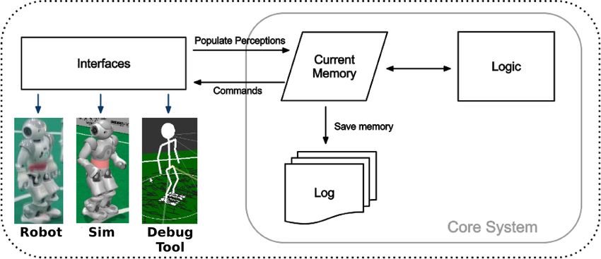
2 Software Architecture
One of the most important aspects of developing RoboCup software is that it
needs to be easily debugable and testable. To this end, we have developed an ar-
chitecture that allows for easy debugging, modification, and testing of individual
modules of the code. The design’s key element is to enforce that the environ-
ment interface, the agent’s memory, and its logic are kept distinct (Figure 2).
In this case logic encompasses the expected vision, localization, behavior, and
motion modules. Figure 3 provides a more in-depth view of how data from those
modules interact with the system.
The design advantages of this architecture are:
Consistency The core system remains identical irrespective of whether the
code is run on the robot, in the simulator or in our debug tool. As a result,
we can test and debug code in any of the 3 environments without code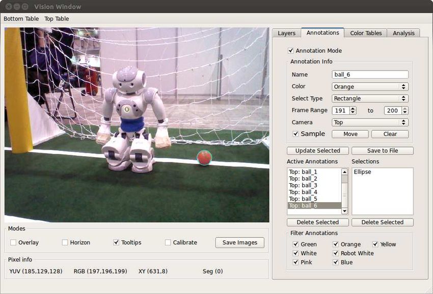
UT Austin Villa 2012        3

Fig. 2. Overview of the UT Austin Villa software architecture, which separates inter-
face, memory, and logic.

   discrepancies. The robot, simulator and tools each have their own interface
   class which is responsible for populating memory. The interface talks with
   the system being run to populate perceptions in memory, and then reads
   from memory to send commands back to the system.
Flexibility The internal memory design is shown in Figure 3. We can easily
   “plug & play” modules into the system by allowing each module to maintain
   its own local memory and communicate to other modules using the common
   memory area. By forcing communication through these defined channels we
   prevent “spaghetti code” that often couples modules together. For example,
   a Kalman Filter localization module reads the output of vision from com-
   mon memory, work in its own local memory and then write object locations
   back to common memory. The memory module takes care of the saving and
   loading of the new local memory, so the developer of a new module does not
   have to be concerned with the low-level saving/loading details associated
   with debugging the code.
Debugability At every time step only the contents of current memory is re-
   quired to make the logic decisions. We can therefore save a “snapshot” of the
   current memory to a log file (or send it over the network) and then examine
   the log in our debug tool and discover any problems. The debug tool not
   only has the ability to read and display the logs, it also has the ability to
   take logs and process them through the logic modules. As a result we can
   modify code and watch the full impact of that change in our debug tool
   before testing it on the robot or in the simulator. The log file can contain
   any subset of the saved modules. For example saving only percepts (i.e. the
   image and sensor readings) is enough for us to regenerate the rest of the
   log file by passing through all the logic modules (assuming no changes have
   been made to the logic code).
   It would be remiss not to mention the main disadvantage of this design. We
implicitly have to “trust” other modules not to corrupt data stored in memory.
There is no hard constraint blocking one module writing data into a location it
should not. For example localization could overwrite a part of common memory
4       UT Austin Villa 2012

that should only be written to by vision. We could overcome this drawback
by introducing read/write permissions on memory, but this would come with
performance overheads that we deem unnecessary.

Fig. 3. Design of the Memory module. The gray boxes indicated memory blocks that
are accessed by multiple logic modules. Dotted lines show connections that are either
read or write only (percepts are read only, commands are write only).

3     Vision

The team’s vision system divides the object detection task into 4 stages, each of
which is carried out on both cameras. These stages are listed below:
 1. Segmentation - The raw image is read and segmented using a color table.
 2. Blob Formation - The segmented image is scanned using horizontal and
    vertical scan lines, and “blobs” are formed for further processing.
 3. Object Detection - The blobs are merged into different objects. In this
    paper, we shall primarily limit our discussion to line and curve detection.
 4. Transformation - the information given by the pose of the robot is used
    to generate ground plane transformations of the line segments detected.
   These processing steps are outlined in detail in our previous technical re-
port [2]. We therefore focus here on the modifications to allow the use of both
cameras, as well as a new set of color table generation and analysis tools.

3.1   Dual Cameras

A major hardware upgrade on the Nao V4 was support for streaming image
frames from both the top and bottom cameras simultaneously. Combined with
improved processing power and faster bus speeds, this made it possible to run
the object detection module on images from both cameras while maintaining the
hardware-enforced framerate limit of 30 Hz.
UT Austin Villa 2012 5
It was quickly determined that merging images would come at high com-
putational cost due to small variations in the camera coloring and orientation.
Ultimately we chose to modularize the existing detection sequence to run on
each camera image. While there is a small amount of overlap between cameras,
this is ignored except in the case of the ball. When the ball is detected in both
cameras, we use the bottom camera’s detection as our selected candidate.
Two key advantages come from this use of both cameras. The first and most
obvious is an increased field of view and thus a greater number of detected
objects. The second advantage is that at specific head tilt levels the robot’s field
of view is guaranteed to range from its feet to the edge of the field. We therefore
keep the head at a constant downward angle and restrict head movements to
horizontal pans. Minimizing head motion in this manner significantly improved
our walk stability, and enabled the creation of camera-specific color tables. The
bottom camera, for instance, can identify a much wider range of YUV tuples
as orange, leveraging the knowledge that this camera rarely has the potential of
seeing false positives in its field of view.
3.2 Color Tables and Analysis
One of the significant modifications to our vision codebase came from a set of
analysis tools intended to improve the process of creating color tables. These
tools include a log annotation system for identifying key regions and objects in
image logs; a color table generation tool based on annotations; and an annotation
analysis tool. The annotation and analysis tools are shown in Figure 4.
(a) Annotations (b) Analysis
Fig. 4. Examples of the annotation and analysis tools in use. The blue circle around
the ball indicates an elliptical region selection for orange.
The annotation system allows us to graphically select regions of particular
images from log data, identify selections by name, and group selection sets over
multiple frames to designate the lifetime of a particular object. The tool pro-
vides the option of selecting regions as rectangles, ellipses, or polygons. Multiple
selections may be combined and labeled by name and color, allowing a user to
indicate all key objects in the frame.
These annotations provide the groundwork for color table generation and
detection analysis. The generator uses each annotation’s assigned label to asso-
ciate all encompassed YUV values with the indicated color. Color assignment6 UT Austin Villa 2012
instances are then aggregated to determine false positives (FP), true positives
(TP), and false negatives (FN). Using this data, YUV-color mappings are then
sorted by their mapping score, F P/(T P + 1). This sorting enables the user to
prune off associations with many false positives. When generating color tables
for the ball, this pruning provides an effective way of removing mappings from
very dark regions under the ball, or from white areas due to reflections on the
ball’s surface. The analysis portion of the tool additionally displays all FP and
FN rates to provide some feedback on the quality of the current color table.
In most cases, no other analysis is provided. When analyzing orange map-
pings, the tool provides feedback on detected ball candidates and selections as
well. The end result is that hundreds of frames of log data can be analyzed
in seconds and instantly provide black-box-style feedback on the efficacy of the
generated (and pruned) color table.
This technique was initially used with all of the field objects, however there
was little to no benefit for colors such as green and white that occur all over
the field. The technique was most effective with the ball, where annotations
were simple to create and evaluate. Initial setup time and overall accuracy of
the resulting color table was comparable with our previous method of creating
tables by hand, however with the added bonuses of measurable accuracy and
simplified ad-hoc adjustments.
4 Localization
For localization and world modeling, our goals were simple: always know where
you are, always know where the ball is, and have a good idea where the opponents
and teammates are as well. Like many other teams at the competition [9, 6],
since 2011 we have used a multi-modal 7-state Unscented Kalman Filter (UKF)
for localization [2]. The UKF provides a number of benefits compared to other
approaches such as Monte Carlo localization as it is computationally efficient and
enables easy sharing and integration of ball information between teammates.
One of the major challenges facing teams in the 2012 RoboCup competition
is that the goals were no longer uniquely colored; instead, they were both yellow.
This change required major changes in the team’s localization system, as now
the robots must track which goal is which from their initial positions. First,
we removed all “resetting” code that would enable a robot to recover from a
kidnapping, as such code could reset the robot to a symmetrical position on the
wrong half of the field. Second, we had to improve and update odometry so the
robot could successfully track and maintain its position from the beginning of
the game using only ambiguous landmarks.
Even with these changes, there were still two problems that arose: bumps
and falls. First, the robot’s odometry can be incorrect if the robot is bumped
or pushed by another robot. Second, if the robot falls down, it is unsure of its
orientation upon getting up. In the corners and edges of the field, the robot knows
its location and can figure out its orientation from looking around. However, at
the middle of the field, two of the orientations are symmetrical. Our solution toUT Austin Villa 2012 7
this problem at the US Open was to have the robot stay down if it fell near the
middle of the field. Rather than risk choosing the wrong direction, it was better to
take the 30 second penalty for failing to get up and be reset in a known location.
While this solution worked at the US Open when all teams (including us) were
still mid-development, we knew that it would not be sufficient for RoboCup.
Clearly, the robot would need to take advantage of shared information from
teammates to resolve which direction it was facing. However, testing and de-
bugging localization with full teams of robots is quite challenging. Therefore,
we wrote a localization simulator to implement, test, and debug our solutions,
shown in Figure 5. The simulator took advantage of the modularity of our code.
Instead of interfacing with the code at the perception and motor command lay-
ers, it populated the code with simulated output from the vision module, and
then used the code’s output to the kicking and walking modules to move the
robots in the simulation. The simulator proved useful not just for localization,
but also for testing various strategies and behaviors, as described in Section 6.
Fig. 5. The localization simulator, showing simulated observations for the green robot
in the center circle, along with that robot’s estimate of its own location in white.
Our final solution to resolving the same-color goal issue was to have robots
check whether their teammates thought the ball was in the same location or in
the symmetrically opposite location. It is important to listen to more than one
teammate, as we do not want one teammate that is going the wrong way to
convince the entire team to start going the wrong direction. Thus, each robot
keeps a counter which is incremented each time it receives an estimate of the
ball within dist-thresh of the symmetrical opposite location of its estimate,
and decremented when it receives a message with the ball within dist-thresh
of its own estimate. If this counter reaches a threshold (opp-ball-thresh), the
robot spawns a new model with high probability placing it in the symmetrical
opposite location of where it was. Through thorough testing in the simulation,
we debugged and tuned the values of dist-thresh and opp-ball-thresh until
this approach worked reliably.
5 Motion
This section describes the walk engine as well as the kick engine that were
used by the UT Austin Villa team in the 2012 RoboCup competition. The walk8 UT Austin Villa 2012
engine was used largely unmodified from an existing implementation, but several
important changes were made to the kick engine in 2012.
5.1 Walk Engine
In 2012, the UT Austin Villa team switched to using the walk engine developed
by the B-Human team from the University of Bremen [10]. To interface this
walk engine with our codebase, we started from the code released by Bowdoin
College’s Northern Bites team [8]. This code was used with mostly small changes,
the largest being the positioning of the arms. Inspired by the 2011 HTWK team,
UT Austin Villa chose to keep the robot’s arms behind its back in order to
reduce side collisions with other robots. This type of collision is especially hard
to avoid when approaching the ball, and it is also difficult to detect, often creating
differences between sensed odometry and actual movement. Therefore, keeping
the arms behind the robot proved to be very helpful.
Another change was in reducing the height of robot’s torso while walking.
Lowering this height increases the stability of the robot, leading it to stay upright
more often when colliding with other robots. However, walking lower puts more
strain on the joints, causing the leg joints to overheat more quickly. This problem
was especially apparent at the end of the finals, when UT Austin Villa’s robots
fell over frequently due to this overheating.
5.2 Kick Engine
Our kick engine was composed of two main kick types: kicks executed from a
static standing position and kicks executed directly from the walk engine. The
static standing kicks were more accurate and could go longer distances, but
required the walk engine to halt and the robot to be in a standing position.
The walk engine kicks, although limited to shorter distances, could be executed
without stopping the walk.
Static Standing Kicks The static standing kicks were a simplified, quicker
version of the kicks we used at RoboCup 2011 [2]. Specifically, we shortened the
interpolation time for executing almost every kick state, and we removed the
second align state that we used in 2011.
For RoboCup 2012, the only static standing kicks that the robots used were
straight kicks ranging between 1.5 meters and 3.5 meters. The kick engine selects
the appropriate parameters for the kick based on the desired kick distance and
the current ball position with respect to the kicking foot. The robot’s joints are
controlled using inverse kinematics to reach each desired state in the allocated
time. Splines are used to compute the path for the foot to follow as it moves
forward during the kick state. The kick engine obtains the desired kick distance
by controlling the amount of time needed to move the foot during the kick
state. The relationship between the interpolation time and the distance was
determined empirically, and varied for each venue based on the field design and
carpet texture.UT Austin Villa 2012 9
Walking Engine Kicks Our strategy in the past couple of years has been to act
quickly at the ball and keep the ball moving as much as possible. Hence, once we
switched to using the walk engine developed by the B-Human team [10], we began
experimenting with executing kicks while the walk engine was still running. We
first considered the walk engine kicks that B-Human included in their release,
but then set out to improve on both their stability and their consistency.
We built upon B-Human’s methodology of adding an offset in the x,y,z di-
rections at selected positions in a normal step to turn the step into a kick. For
each of the walk engine kicks, we picked four or five times in a normal step and
defined the amount that should be added in the x,y,z directions to the swing foot
and the stance foot. We then used splines to fit a smooth curve for the amount
to be added to the normal foot positions for both the stance foot and the swing
foot at each time when commands are sent to the robot during a walk engine
kick.
In this manner, we implemented a 1.25 meter straight kick, a 1.0 meter 45
degree kick, and a 0.75 meter side kick that could be executed from the walk
engine. None of the walk engine kicks adapt to the position of the ball, but they
are only attempted if the robot approaches the ball such that the ball is in an
acceptable position for executing the desired walk engine kick.
6 Behavior and Strategy
Our strategy was focused on three goals: 1) move the ball quickly; 2) move it
up-field towards the goal; and 3) keep the ball away from opponents. A key
component for our strategy was our module for selecting which of the possible
kicks to make [3]. This module iterated through an ordered list of kicks, selecting
the first acceptable kick, one that would move the ball towards the goal while
keeping it away from opponents. This procedure gave the robot speed compared
to the option of always turning to kick the ball directly at the goal.
One problem with this strategy is that it focused on quickness, even when
there were no opponents around and the robot could have taken more time to
make a better kick. One focus for this year was to judge how much time the robot
had to kick, based on how close the opponents were to the ball. We introduced
three thresholds. If the nearest opponent was very far away, the agent decided
it had time to rotate around the ball to make a long kick directly at the goal.
If the nearest opponent was closer than this threshold but not very close, then
the agent would not rotate at all, but could choose from a set of stronger, slower
kicks that required the robot to stop walking. If the opponents were within even
a smaller radius, then the robot chose from one of its kicks that it could execute
from the walk engine, without having to stop walking. Finally, if the opponent
was directly at the ball, the robot would choose to make a quick side kick 90
degrees to one side. Its goal was to choose the side free of opponent robots, or
the side with a teammate robot if there were no opponents on either side. This
decision making process enabled our agents to take advantage of when they had10 UT Austin Villa 2012
more space to align for better kicks, while still being very quick at moving the
ball when they had to be.
The localization simulator enabled us to perform significant testing and de-
bugging of our strategies and kick selections. One of the main changes that came
out of these tests was the positioning of players away from the ball. We split the
field into two regions. In the back third of the field, one robot stayed to the side
of the ball to receive side kicks, and one forward positioned itself a few meters up
from the ball. In the rest of the field, one robot stayed to the side to receive side
kicks, and one defender stayed back from the ball a few meters. This positioning
proved to be very successful at the competition, as the team completed many
side kicks to the support player, and the defender was ready to come up and
contest the ball if the opponents got by the attacker.
One major issue at RoboCup every year is handling problems with wireless
communication, and this was a problem again in 2012. Our robots depend on
wireless communication to share ball information, resolve ambiguous orientations
that result from the same-colored goals, and decide on which position each robot
should play. Once it became clear that wireless would be an issue for the entire
competition, we developed a new positioning strategy for this scenario. If the
robots detected that wireless was down, one would permanently chase the ball,
while the other two went to static positions on the field. However, these two field
players would still go to kick the ball if it reached within a set distance of them.
This strategy appeared to be better than the approaches other teams took, such
as removing all but one robots from the field, or letting all the robots go to the
ball all the time.
7 Competition
In 2012, UT Austin Villa won the Standard Platform League at the 16th Inter-
national RoboCup Competition in Mexico City, Mexico. 25 teams entered the
competition and games were played with four robots on each team. The tourna-
ment consisted of two round robin rounds, followed by an elimination tournament
with the top 8 teams. UT Austin Villa’s scores are shown in Table 1.
In the first round robin, UT Austin Villa was in a group with Nao Team
Humboldt and MRL. UT Austin Villa defeated both teams 8-0 to win the group.
Round Opponent Score
Round Robin 1 Nao Team Humboldt 8-0
Round Robin 1 MRL 8-0
Round Robin 2 Nao Devils 5-1
Round Robin 2 Kouretes 8-0
Round Robin 2 NTU RoboPAL 9-0
Quarterfinal AUTMan 5-0 (forfeit)
Semifinal rUNSWift 7-6
Final B-Human 4-2
Table 1. RoboCup 2012 ResultsUT Austin Villa 2012 11
In the second round robin, UT Austin Villa was placed with the Nao Devils,
Kouretes, and NTU RoboPAL. UT Austin Villa defeated the Nao Devils 5-1,
Kouretes 8-0, and NTU 9-0 to place first in the group. UT Austin Villa played
AUTMan in the quarter-finals, where UT Austin Villa won 5-0 after AUTMan
opted for a forfeit partway through the game due to techinical difficulties. In
these games, UT Austin Villa experienced wireless issues but was still able to
test various strategy parameters to prepare for the semi-finals and finals.
In the semi-finals, UT Austin Villa faced rUNSWift from The University
of New South Wales. rUNSWift went up 2-0 and was ahead by 3-1 before the
first half ended with rUNSWift claiming a 3-2 advantage. In the second half,
rUNSWift extended its lead to 4-2 before UT Austin Villa tied it up at 4-4.
rUNSWift and UT Austin Villa then alternated goals until they were once again
tied at 6-6. Then, UT Austin Villa called a 5 minute timeout, during which we
implemented and uploaded an untested code change that would keep our goalie
from diving immediately after a kickoff. We chose to make this change because
rUNSWift’s long kickoffs towards the left corner of our goal box were causing
our goalie to dive on the kickoff and not recover in time to clear the ball. After
the timeout, UT Austin Villa claimed its first lead of the game, 7-6, with about
80 seconds left, and held on to win what several observers felt was the most
competitive SPL RoboCup game to date.
Less than two hours after winning their semi-final game, UT Austin Villa
faced previously undefeated B-Human from the University of Bremen in the
championship game. UT Austin Villa took advantage of an empty field after
B-Human’s robots were called for ball holding penalties to take an early 1-0
lead. UT Austin Villa’s lower walk stance height than B-Human gave them
better walk stability. Using this advantage and good positioning of its robots,
UT Austin Villa claimed a 2-0 lead in the first half, and extended the lead to
4-0 in the second half. However, the lower walk stance led to UT Austin Villa’s
robots’ knees over-heating, reducing their stability and creating problems with
getting up. B-Human took advantage of this weakness to score two late goals,
but not enough time remained for them to complete a comeback. UT Austin
Villa won the championship game 4-2.
8 Conclusion
This paper describes the technical work done by the UT Austin Villa team that
led to its 2012 championship in the Standard Platform League. Importantly, all
of the 2012 code was developed on a flexible architecture developed previously,
that enables easy testing and debugging of code. This year, we updated the
vision code to take advantage of the dual cameras and better processor of the
new Nao robots. To improve localization, we developed a localization simulator,
allowing us to implement and test a full team solution to the challenge of both
goals being the same color. Our 2012 team made use of Northern Bites’ port of
B-Human’s walk engine, combined with novel kicks from the walk. Finally, we
implemented new behaviors that would take advantage of when the robots had12 UT Austin Villa 2012
time to setup for a long kick, and kick very quickly when there were other robots
around. The combination of all of these contributions led the team to victory
at RoboCup 2012 and gives us a good foundation to field competitive teams in
future competitions.
Acknowledgements
This year’s team builds upon all of the past UT Austin Villa teams. We thank all
the previous team members for their important contributions, especially Michael
Quinlan and Mohan Sridharan. This work has taken place in the Learning Agents
Research Group (LARG) at UT Austin. LARG research is supported in part by
NSF (IIS-0917122), ONR (N00014-09-1-0658), and the FHWA (DTFH61-07-H-
00030).
References
1. S. Barrett, K. Genter, M. Hausknecht, T. Hester, P. Khandelwal, J. Lee, M. Quin-
lan, A. Tian, P. Stone, and M. Sridharan. Austin Villa 2010 standard platform team
report. Technical Report UT-AI-TR-11-01, The University of Texas at Austin, De-
partment of Computer Sciences, AI Laboratory, January 2011.
2. S. Barrett, K. Genter, T. Hester, P. Khandelwal, M. Quinlan, P. Stone, and M. Srid-
haran. Austin Villa 2011: Sharing is caring: Better awareness through information
sharing. Technical Report UT-AI-TR-12-01, The University of Texas at Austin,
Department of Computer Sciences, AI Laboratory, January 2012.
3. S. Barrett, K. Genter, T. Hester, M. Quinlan, and P. Stone. Controlled kicking un-
der uncertainty. In The Fifth Workshop on Humanoid Soccer Robots at Humanoids
2010, December 2010.
4. T. Hester, M. Quinlan, and P. Stone. UT Austin Villa 2008: Standing on Two Legs.
Technical Report UT-AI-TR-08-8, The University of Texas at Austin, Department
of Computer Sciences, AI Laboratory, November 2008.
5. T. Hester, M. Quinlan, P. Stone, and M. Sridharan. TT-UT Austin Villa 2009:
Naos across Texas. Technical Report UT-AI-TR-09-08, The University of Texas
at Austin, Department of Computer Science, AI Laboratory, December 2009.
6. G. Jochmann, S. Kerner, S. Tasse, and O. Urbann. Efficient multi-hypotheses
unscented kalman filtering for robust localization. In RoboCup 2011: Robot Soccer
World Cup XV, page to appear. 2012.
7. H. Kitano, M. Asada, Y. Kuniyoshi, I. Noda, and E. Osawa. RoboCup: The robot
world cup initiative. In Proceedings of The First International Conference on
Autonomous Agents. ACM Press, 1997.
8. O. Neamtu, W. Dawson, E. Googins, B. Jacobel, L. Mamantov, D. McAvoy,
B. Mende, N. Merritt, E. Ratner, N. Terman, J. Zalinger, J. Morrison,
and E. Chown. Northern Bites code release, 2012. https://github.com/
northern-bites.
9. M. Quinlan and R. Middleton. Multiple model kalman filters: A localization tech-
nique for robocup soccer. In 2009 RoboCup Symposium, 2009.
10. T. Röfer, T. Laue, J. Müller, A. Fabisch, F. Feldpausch, K. Gillmann, C. Graf, T. J.
de Haas, A. Härtl, A. Humann, D. Honsel, P. Kastner, T. Kastner, C. Könemann,
B. Markowsky, O. J. L. Riemann, and F. Wenk. B-human team report and code
release, 2011. http://www.b-human.de/downloads/bhuman11_coderelease.pdf.You can also read