VENDLET V5S V5S Speed Adjust Bari - EN
←
→
Page content transcription
If your browser does not render page correctly, please read the page content below
VENDLET
EN    User Manual
                                      V5S
                                      V5S Speed Adjust
                                      Bari

 D H G - H E A LT H C A R E . C O M
VENDLET V5S/V5S SPEED ADJUST/BARI

2         DHG-HEALTHCARE.COM

USER MANUAL

Congratulations on your new VENDLET. The VENDLET is used for handling bedridden clients, for example:
•     Turning to lateral, prone or supine positions
•     Moving from one side of the bed to the other
•     Repositioning the client up in the bed
•     Transferring the client from one bed to another
This manual covers the following 3 VENDLET models:
 VENDLET V5S                                         Max . user weight 200 kg                            1 speed
 VENDLET V5S Speed Adjust                            Max . user weight 200 kg                            3 speeds
 VENDLET Bari                                        Max . user weight 400 kg                            3 speeds
Whenever this manual refers to VENDLET, it applies to all 3 models. If the situation only applies to one or more of the models, it will
refer specifically to each model.
The instructions in this manual must be followed. Vendlet ApS shall not be liable should the VENDLET be used, modified, or assembled
in a way that is not described in this manual.
This manual is divided into three parts:
•     Part 1 contains general information that is useful to everyone responsible for the purchasing, examination, use, assembly, and
      maintenance of the VENDLET.
•     Part 2 is a user manual containing information about the operation and daily maintenance of the VENDLET.
•     Part 3 is a technical manual containing information about the assembly, maintenance, and service of the VENDLET.

Contents
Part One: General Information
Intended Use ........................................................................................................................................................................ 04
Product Description .............................................................................................................................................................. 04
Bed & Mattress Compatibility ................................................................................................................................................ 06
Warranty & Service Life ......................................................................................................................................................... 07
In the Event of an Incident ..................................................................................................................................................... 07
Symbols ............................................................................................................................................................................... 08

Part Two: User Manual
Operation ............................................................................................................................................................................. 09
Attaching the Sheets ............................................................................................................................................................. 14
Evacuation ........................................................................................................................................................................... 16
Daily Maintenance & Troubleshooting ..................................................................................................................................... 16

Part Three: Technical Manual
Unpacking ............................................................................................................................................................................ 18
Parts List ............................................................................................................................................................................. 18
Mounting ............................................................................................................................................................................. 18
Quick Guide Location ............................................................................................................................................................ 26
Additional Accessories .......................................................................................................................................................... 26

                                                                                DHG-HEALTHCARE.COM                                                                                            3
VENDLET V5S/V5S SPEED ADJUST/BARI
Final Inspection List .............................................................................................................................................................. 27
Dismounting, Storage & Remounting ...................................................................................................................................... 28
Maintenance/Check .............................................................................................................................................................. 28
Troubleshooting - Technicians ............................................................................................................................................... 29
Repairs ................................................................................................................................................................................ 30
Spare Parts ........................................................................................................................................................................... 32
Technical Data ...................................................................................................................................................................... 32
Environmental Conditions & Disposal ..................................................................................................................................... 32
PART ONE: GENERAL INFORMATION VENDLET Bari has a load capacity of 400 kg. The target group
this model is bedridden bariatric clients.
Intended Use
Prior to the first use of the VENDLET, it is important to assess
The VENDLET may be used for moving clients to a lateral, prone,
whether the VENDLET is suitable for the client in question. It may
or supine position, from one side of the bed to the other, or, to
be necessary to take special precautions, for example if a client
reposition them further up in bed. The VENDLET may also be
is very restless in bed or has an untypical anatomy.
used in connection with mobilisation in and out of bed and when
transferring clients from one bed to another. For safety reasons, it is recommended that the VENDLET is not
operated by the bedridden person.
The VENDLET protects the caregiver from physical strain and
heavy lifting in connection with the handling of immobile clients. Contraindications
Clients are turned/handled by pressing a hand control whereby Do not use the VENDLET for clients with unstable fractures,
the caregiver may support a client and ensure their correct gross oedema, burns or equilibrium disorders.
and comfortable positioning. This provides room for increased
awareness in the care, which boosts employee job satisfaction Prior to the first use of VENDLET, it is important to assess
and client well-being. whether VENDLET is suitable for the client in question. It may be
necessary to take special precautions, for example if a client is
To the client, the turning process becomes uniform and steady very restless in bed or has an untypical anatomy.
as the sheet supports the body over its full length.
The target group is clients who are being cared for, dressed,
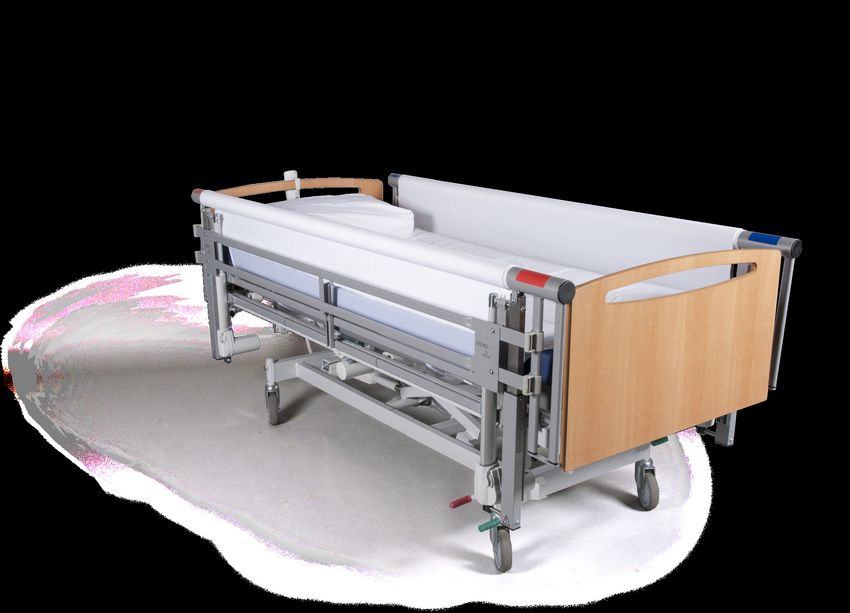
Product Description
washed etc. in bed. This will often be clients who are lifted in The VENDLET system consists of two bars fitted with motors.
and out of bed or clients who are mobilised using a standing aid. The bed is fitted with a motorised bar on both sides; the bar on
Hence, the user will typically be clients with few physical and/or the left side of the client has a blue colour marking and the bar
cognitive resources and palliative clients. on the right side of the client has a red colour marking. Each
motorised bar is fitted with a long velcro strip which makes it
The VENDLET is also suitable for clients at risk of developing
possible to attach a long turning sheet between the two bars.
pressure ulcers in that the uniform and steady transfer in the
The turning sheet is wrapped around the two bars, making it
sheet minimises friction and the associated shear that can
possible to move it from side to side.
damage the tissue and cause pressure ulcers. Furthermore, the
A slide sheet is inserted under the turning sheet in order to
VENDLETs often seem to have a positive effect on clients
reduce the friction of the turning sheet against the mattress.
suffering from spatial awareness.
The bars are fitted with an actuator at each end in order to raise
The VENDLET is intended for clients weighing at least 30 kg.
and lower the bars.
For clients weighing less than 50kg take extra care
To allow the individual adjustment of the VENDLET to any bed
not to lift the client from the bed when the system is
and mattress, the actuators are mounted on height-adjustable
in operation.
brackets.
VENDLET V5S / VENDLET V5S Speed Adjust has a load capacity
Furthermore, the VENDLET consists of a control unit and a hand
of max. 200 kg.
control. The control unit is placed underneath the bed.
4 DHG-HEALTHCARE.COM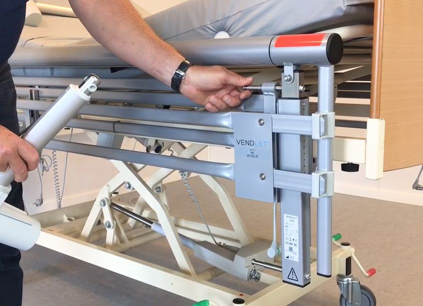
USER MANUAL

                             Red bar
                                                 Hand control

                                                                                                                           Blue bar
                                                                     Turning sheet

                                                        Slidesheet

                                             Actuator

                                                                                           Fitting for actuator

When the bars are raised VENDLET can be used as side rails.                  in both directions or raised or lowered. The colour coding on the
Note! This applies only to the VENDLET models that this manual               bars relates to the colours on the hand control buttons.
covers.
                                                                             With VENDLET V5S Speed Adjust and VENDLET Bari the speed
How VENDLET Works                                                            of the bars can be reduced, so the speed is running at 75% or
                                                                             50% of normal.
The VENDLET is switched on by double-clicking the    on the
hand control. The VENDLET produces a “beep” upon activation                  Press and hold the individual buttons long enough to obtain
and the green diode over the power symbol turns on.                          the desired operation; the motors will stop when the button
                                                                             is released. Likewise, you may stop an activated function by
When a VENDLET has been inactive for 90 seconds, the system
                                                                             clicking the .
produces a “beep-beep” sound, the diode turns off, and then the
VENDLET system is off again.                                                 When the bar is up on the side where the turning sheet is being
                                                                             tightened, the client will be turned. If, on the other hand, the bar
When the VENDLET has been turned on, the bars can be turned

                                               Tighten the sheet on                                               Tighten the sheet on
                                               the red bar                                                        the blue bar
                                               Slacken the sheet on                                               Slacken the sheet on
                                               the red bar                                                        the blue bar

                                               Raise the red bar                                                  Raise the blue bar

                                               Lower the red bar                                                  Lower the blue bar

                                               Speed Adjustment                                                   Flash light /
                                                                                                                  Under bed light (accessory)
                                               Power w.
                                               illuminated diode /
                                               stop button

                    Hand control for:                                                Hand control for:
                    VENDLET V5S                                                      VENDLET V5S Speed Adjust
                                                                                     VENDLET Bari

                                                           DHG-HEALTHCARE.COM                                                                       5
VENDLET V5S/V5S SPEED ADJUST/BARI

is down on the side where the turning sheet is being tightened,          are available, see page 26.
the client will be moved towards the edge of the bed. These
                                                                         Additional hand control:
fundamental principles provide you with a number of ways to
move and/or transfer clients. See the “How to Use the VENDLET”           An additional hand control can be connected if a hand control is
section in Part 2 – User Manual for further details.                     required on both sides of the bed, see page 24.

The VENDLET can be operated by only one person (caregiver or             Wider sheets:
relatives etc).                                                          Wider turning sheets and slide sheets are also available if the
Warnings                                                                 VENDLET is to be used on wider beds, see page 14.

           As it is recommended that the clients does not operate        Battery backup and under bed light:
           the VENDLET themselves, the hand control must be              Additionally, a battery backup is available to operate the
           placed on the outside of the bed before leaving the client.
                                                                         VENDLET without a connection to the supply network. We
                                                                         also provide an under bed light that may be activated via the
           Lowering the bed to a very
           low position may leave the
                                                                         VENDLET hand control, see page 26.
           actuator bracket very close
           to the floor. Consequently,                                   Bed & Mattress Compatibility
           you should not place your                                     The VENDLET is intended for mounting on a wide range of
           feet under the actuator                                       hospital and care beds and with a wide range of mattresses. The
           fittings.                                                     following bed and mattress requirements must be met.
           The bed’s lowest height
                                                                         Bed requirements
           can be restricted on certain
           types of beds by mounting                                     The bed must meet the EN 60601-2-52 standard or the expired
           height restriction brackets.                                  EN 1970 or EN 60601-2-38 standards.
                                                                         The bed must have a square steel frame (dimensions H 45-50
           If the client has long and loose hanging hair, the hair       mm, W min. 20 mm, L min. 195 cm. without protrusions). The
           could in some situations be rolled onto the bar, when
                                                                         bed width is not crucial as extra wide turning sheets and slide
           the sheet is tightened. Therefore, long loose hair should
           always be collected before moving and handling the            sheets are available.
           client.                                                       VENDLET can be mounted on most beds with these dimensions.
                                                                         But situations where VENDLET cannot be mounted can occur.
           The client must not hold on to the edge of the turning
           sheet or bar during the transfer. If the client is restless
                                                                                    The maximum user weight and safe working load
           and needs something to hold on to, we recommend they
                                                                                    of the bed must not be exceeded following the
           get a handle such as a FlexiGrip
                                                                                    installation of VENDLET.

Accessories                                                              Mattress Requirements
Height extensions, spacers, side rail extensions and                                The mattress must meet the requirements of the
brackets:                                                                           bed manufacturers and be suitable for the bed.
If particularly thick mattresses are used, it may be necessary to
use height extensions, see page 23. Further, it may be necessary         The maximum user weight specification of the mattress must not
to use spacers if the distance between the VENDLET system and            be exceeded.
the mattress is insufficient, see page 22. Spacers and height
extensions are available as accessories.                                            Following the mounting of the VENDLET, the
The system is standard 200 cm long. When using extra-long                           distance between the mattress sides and side rails
beds, it can be necessary to extend the length of the VENDLET                       must be minimum 2.5 cm and maximum 4 cm, see
system, see page 23.                                                                page 19.

Brackets that makes installation on different types of beds easier

6                                                             DHG-HEALTHCARE.COM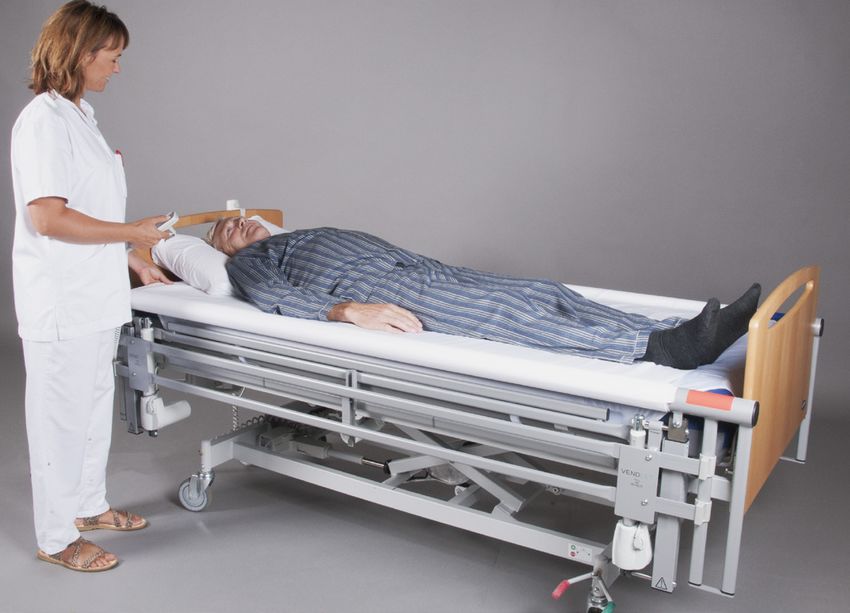
USER MANUAL

           If the mattress is soft and easily compressible,
           it must be ensured that there is no entrapment
           hazard due to extra compression at the edge of the
           mattress.

When alternating air mattresses are used, it should be possible
to inflate the mattress to a firm state before VENDLET is
operated. Soft mattresses will increase the friction against the
mattress and create an uneven base which will be
uncomfortable for the client when VENDLET is operated.

           If the client changes mattress, the VENDLET
           installation must be evaluated. A new mattress
           might change the conditions and necessitate the
           reinstallation of VENDLET to reduce the risk of
           entrapment.

Warranty & Service Life
DHG provides a 1-year factory warranty on all electric parts.
Opening the control unit, actuators, or hand control will void the
warranty.
        Certain types of care and hospital beds have a particularly
        long bed frame, which means that the actuator may collide
        with the bed brake, when the bed is lowered. Further, the
        mattress frame may in some cases collide with the actuator, if
        head end or foot end is lowered considerably.

Damage to the actuator, due to collision with bed parts, are not
covered by the warranty.

To prevent the above problem by limiting the bed’s lowest height,
or by turning the actuator, read more on pages 26.

DHG provides a 3-year warranty on all mechanical parts (except
sheets).

The normal VENDLET service life is 10 years. The service life
may be significantly extended if the product is used and handled
with care and maintained in accordance with the guidelines in
this manual.

In the Event of an Incident
In case of an adverse event or a near-accident involving the
VENDLET system, the accident must be reported to the
competent authority in the country in which the accident
happened.

Likewise, we kindly request that you also inform DHG on
tel. +44 (0) 800 043 0881 or info@directhealthcaregroup.com

                                                            DHG-HEALTHCARE.COM   7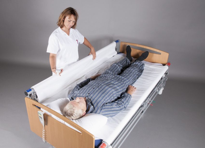
VENDLET V5S/V5S SPEED ADJUST/BARI

Symbols
                      CE marking: The product complies with the
                      Medical Device Regulation (EU) 2017/745
         MD           This product is a medical device

                      Legal manufacturer

                      Date of manufacture

                      Serial number

                      Item no. / Catalogue number: 7 digits

                      Unique Device Identification

                      Consulting the manual is mandatory
                      Warning triangle indicates when special attention
                      is necessary
                      For indoor use

                      This product is a class ll equipment (IEC 61140)
                      The product is a type B equipment according to
                      EN 60601-1
                      Max. user weight
                      Electronic scrap. When disposing of the products,
                      sub-components should be recycled
            40°C

     5
                      Product must be operated between 5 and 40˚C.
            50°C

     0
                      Product must be stored between 0 and 50˚C.
                90%

                      Product must be stored between 20 and 90%
    20
                      humidity at 30˚C.
                      Keep dry (during storage)

         Rev.         Revision no of the label. Printed vertically.

                      Power / stop button

                      Speed Adjustment

                      Tighten the sheet on the red or blue bar

                      Slacken the sheet on the red or blue bar

                      Raise the red or blue bar

                      Lower the red or blue bar
                      Light on Speed Adjust hand control or under bed
                      light on hand control without speed adjust

8                                                                     DHG-HEALTHCARE.COM
USER MANUAL

PART TWO: USER MANUAL
Operation
Handling clients with a VENDLET system enables caregivers to
work on a one-to-one basis: one hand is used to operate the
hand control and the other hand is free to guide the arms and
legs of the client. In order to improve the safety and well-being
of the client, we recommend that you place the hand holding the
hand control on the shoulder of the client or similar.
You should always use the resources of the client. For example,
if the client can move his/her arm to the side, he or she should
do so.

              Always, keep focus on the client when using VENDLET.      Guide the right arm of the client to the side

              Remember to leave the hand control on the outside of
              the bed before leaving the client.

How to use VENDLET
Turning
The VENDLET may be used to turn clients. Follow this procedure
to move a client from a supine position to lying on his/her right
side:
1. Double-click the       button to activate the VENDLET.
2. Press the       button to raise the blue bar.
3. If necessary, press once or twice on         to reduce speed
   (Speed Adjust).                                                      Shift the left leg of the client in parallel above the right leg

4. Press the       button to tighten the turning sheet on the blue
   bar.
                                                                        Watch instruction videos on our webpage
5. Place the left arm of the client on his/her stomach or chest         vendlet.com or scan the QR-code.
   the moment before he/she starts turning.
6. Immediately after this, guide the right arm of the client to
   the side.
7. Then shift the left leg in parallel above the right leg.             Moving from one side of the bed to the other

8. The client now lies on his/her right side.                           The VENDLET may also be used to move clients to the side of
                                                                        the bed.
The red bar does not necessarily have to be raised. But if this
makes the client or the caregiver feel more safe, the red bar           1. Double-click the                   button to activate the VENDLET.
could be raised during the process.                                     2. Press the    and                      buttons to lower the bars if they have
Moving clients with the VENDLET is ideally suited for dressing             been raised.
and access to care tasks and hygiene, applying a sling, and             3. If necessary, press once or twice on                            to reduce speed
repositioning.                                                             (Speed Adjust).
                                                                        4. Use the bar on the side to which the client should be moved
                                                                           and tighten the turning sheet.

                                                              DHG-HEALTHCARE.COM                                                                             9
VENDLET V5S/V5S SPEED ADJUST/BARI

In many situations, this will give the caregiver a better work
posture, for example in connection with examinations, training,
care tasks, dressing, etc.

                                                                           Gently guide the slack turning sheet towards the upper end of the bar

Sound work posture in connection with examination

Repositioning the client up in the bed
It is a well-known problem that clients often slide down to the
foot end, for example when the back support has been raised –
even if the kneebreak on the bed was activated before the back
support.
Typically, when a client slides towards the foot end, the turning
sheet follows the body of the client. In such situations, you may
use the VENDLET to move the client up in the bed again.
1. Double-click the              button to activate the VENDLET.
2. Press the            and        buttons to lower the bars if they are   The turning sheet is now almost back in place
   raised.
3. If necessary, press once or twice on              to reduce speed
   (Speed Adjust).                                                         Watch instruction videos on our webpage
                                                                           vendlet.com or scan the QR-code.
4. Press the            and        buttons to slacken the turning sheet.
5. Stand next to the headboard and press the         or     button
   to pull the client from side to side while you gently guide the
   turning sheet towards the upper end of the bar.                         Applying a sling
6. Repeat the procedure on the opposite side and so on until               It is easy to apply a sling on the client when VENDLET is used.
   the sheet has been completely repositioned and the client is            1. Double-click the  button to
   moved up in the bed again.                                                 activate VENDLET.
                                                                           2. Use the turning function of the VENDLET system to
                                                                              move the
                                                                              client onto his/her side.
                                                                           3. Place the sling along the back of the client and make
                                                                              sure that the sling is centred and correctly placed

10                                                               DHG-HEALTHCARE.COM
USER MANUAL
in accordance with the instructions of the sling
manufacturer.
4. Use the VENDLET turning function to move the client
onto his/her back again.
5. Free the straps on the opposite side.
6. Place all straps in such a way that they are ready to be
placed on the lifting beam of the hoist.
Watch instruction videos on our webpage
vendlet.com or scan the QR-code.
All straps are in place, and the client is ready for transferring
Prone position
The VENDLET can also be used to turn a client to a prone
position.
1. Double-click the button to activate VENDLET.
2. Place the clients right arm closely along his body with the
palm of the hand facing the thigh. Move the pillow and, if
necessary, place it close to the right upper arm so that the
Place the sling along the back of the client
client comes to lie with his chest on top of the pillow.
3. Press the button to raise the blue bar.
4. If necessary, press once or twice on to reduce speed
(Speed Adjust).
5. Press the button to wind the turning sheet onto the blue
bar. The VENDLET system now turns the client. Hold your
hands on the client’s shoulder and hip to provide a sense of
safety during the procedure.
6. Gently support the client as he/she is being turned to prone
position.
7. Check that the clients head is comfortable and that there is
room for breathing.
Pull the straps out on the opposite side
Watch a video on how to prone a client on our
webpage www.vendlet.com or scan the QR-code.
DHG-HEALTHCARE.COM 11VENDLET V5S/V5S SPEED ADJUST/BARI
Transferring from one bed to another
When the client lies on a VENDLET, the VENDLET - in combination with
a slide board and a slide sheet - may be used to transferring the client
onto another bed.
1. First use VENDLET’s turning function to place the sliding board
underneath the client. Insert the sliding board from the side that is
turned towards the new bed.
2. Press the or button to lower the bar facing the other bed.
3. Press the or button to raise the opposite bar.
4. Place a slide sheet on the other bed.
5. Place the other bed right next to the bed with the VENDLET and
Place the client’s right arm closely along his body lower or raise the bed to a slightly lower position relative to the
bed with the VENDLET.
6. Remember to lock the wheels on both beds.
7. Press the or button to pull in the turning sheet on the bar
facing the other bed. Now, the VENDLET transfers the client and
the slide board to the other bed and the slide sheet.
8. Hold the slide board with your hands and pull to move the client to
the centre of the bed.
9. Remove the slide board and the slide sheet.
Side rail
If it is assessed that the bedridden must use side rails, the
VENDLET models described in this manual all have integrated
side rails.
1. Press the and button to raise the bar to the highest
Gently support the client as he is being turned to prone position. position.
2. Press the and button to slacken the sheet before the
client is left unattended in the bed.
Note: All previous VENDLET models require the use of plastic
plates!
Check that the client’s head is comfortable and that there is room for breathing.
VENDLET V5S, VENDLET V5S Speed Adjust, VENDLET Bari has an integrated side rail
12 DHG-HEALTHCARE.COMUSER MANUAL
Urine bag and drainage tube
Using VENDLET in combination with bed functionality If the client has a catheter or a drainage tube, it may be
None of the VENDLET models interfere with the functionality of necessary to adjust the tubes, etc. individually.
the bed. Slacken the turning sheet before raising the back, thigh, Placing the urine bag or drainage tube at the foot end will often
and/or foot part of the bed. be an optimal solution. Should this not be possible, however, you
Under normal circumstances, the bed surface must be level could use long tubes with a view to hanging the urine bag or
before you use the VENDLET. drainage bag on the outer surface of the VENDLET system.
In such cases, the bag should be placed on the bed frame by the
In some situations, however, it may be advantageous to use the footboard and the tube routed between the footboard and the
back or foot part of the bed when moving or turning clients. For VENDLET bracket. Be careful to avoid squeezing the tube.
example, if the client has wide hips and frail shoulders, he/she
will rest more comfortably on the bed if the head and foot parts
are raised a little before the process.
Stop button
The power button also functions as a stop button.
If the hand control button controlling the tightening of the sheet
fails, the operation can be stopped by pressing the button
Pressure-relieving mattresses
The VENDLET systems do not reduce the effect of either
pressure-relieving mattresses or alternating air mattresses.
Pressure measurements have been performed which
unambiguously show that the VENDLET systems do not have
a negative impact on the pressure-relieving properties of the
mattresses.
To prevent interference with the function of alternating air
mattresses, the turning sheet must be sufficiently slackened
before a client is left unattended in the bed.
At the same time, the velcro band on the slide sheet must not be
fastened too tightly around the steel frame under the mattress,
see also the section on mounting the slide sheet, page 14.
We recommend that alternating air mattresses are firmly inflated
before patient handling as this brings higher comfort to the client
during the process.
Incontinence
VENDLET can also be used for clients using incontinence sheets.
The incontinence sheet should have a minimum width of 125
cm so that it can follow the client’s movements during turning.
You should not use two small incontinence sheets as the client
in this case will lie on a double edge, which increases the risk of
developing pressure ulcers.
The incontinence sheet must not be wrapped around the bars,
but instead must hang loosely out over the bars.
DHG-HEALTHCARE.COM 13VENDLET V5S/V5S SPEED ADJUST/BARI
Attaching the sheets mattress should be fully inflated during fitting.
Place a slide sheet directly on top of the mattress, followed by
the turning sheet which is then attached to the two bars. Slide Turning sheet
sheets and turning sheets are available in standard bed sizes Attaching the turning sheet before use
and with increased width which makes the VENDLET systems
suitable for wider beds as well. 1. Place the turning sheet
in the middle of the
Slide sheet width Fits mattress widths Fits mattress length
bed, velcro tape facing
95 cm (regular size) 80 - 90 cm 200 - 210 cm
downward.
95 cm - long 80 - 90 cm 210 - 220 cm
115 cm 95 - 110 cm 200 - 210 cm 2. Press the turning sheet
115 cm - long 95 - 110 cm 210 - 220 cm onto the velcro strip on
135 cm 110 - 130 cm 200 - 210 cm one of the bars; begin at
the head of the bed and
Turning sheet width Fits mattress widths
work your way down to
350 cm (regular size) 80 - 110 cm
the foot end.
400 cm 110 - 130 cm
Slide sheet
1. Fold the slide sheet corner elastic straps around the 3. The turning sheet must
mattress. always be placed OVER
the bars to prevent
2. Check that the surface is smooth and even without creases the fingers, hair etc. of
and folds. Make sure that slippery side is facing upwards. the client from getting
3. Fasten the velcro tapes around the mattress frame. caught under the sheet.
It is important that the tapes are fastened around the The pulling power will
frame under the mattress and not around the bed be reduced and the motors will switch off when the turning
frame as this will prevent the back, thigh, and foot parts of sheet is pulled in by the bar if the sheet is placed under the
the bed from being raised. The tapes are long enough for bars.
thick mattresses. 4. Press the or button on the hand control and allow
approx. two-thirds of the sheet to be pulled in by the bar.
5. Press the turning sheet onto the velcro strip on the opposite
bar.
6. Use this bar to pull in the turning sheet by pressing the
or , button until the sheet covers the mattress evenly
with the red line at the centre of the mattress.
What should I do if the turning sheet is rolled askew on the
The slide sheet is subject to extensive wear and must be bars?
checked regularly. The friction of the turning sheet against the Occasionally, the turning sheet will roll askew on the bars. As
mattress will increase if the bed is not fitted with a slide sheet or such, this is insignificant and the VENDLET system will still be
the slide sheet has been damaged. That will reduce the comfort operable.
of the client during moving and handling.
This could result in creases in the turning sheet under the client
When an alternating air mattress is fitted with a slide sheet, it which is undesirable. Hence, we recommend that you aim to
is important that the velcro tapes are not fastened around the smooth the turning sheet if the sheet is askew on the bars by
frame under the mattress too tightly as this could interfere with more than a hand’s width.
the function of the alternating air mattress. Consequently, the
14 DHG-HEALTHCARE.COMUSER MANUAL
In this situation, you will have to slacken the sheet that has been
pulled askew and pull it in again while guiding / smoothing it
with your hand.
Changing the turning sheet on an occupied bed
1. Position the client on his/her side and then move him/her to
the centre of the bed.
2. Remove the old turning sheet from the bar facing the back
of the client and fold the sheet in layers with a width of
approx. 15 cm. Place it behind the back of the client.
3. Attach the new turning sheet to the bar and press or
button to roll the new turning sheet onto the bar. Allow
approx. half of the new turning sheet to roll onto the bar and Place the new turning sheet under the turning sheet being replaced
stop when the red line on the sheet is at the centre of the
mattress. Fold the remaining part of the new turning sheet
in layers of 15 cm and place it under the turning sheet
being replaced.
4. Move the client to a supine position on top of the folded new
and old turning sheets, and then on to the opposite side by
activating the bar with the old turning sheet.
5. Remove the old turning sheet and attach the replacement
sheet to the bar.
Watch instruction videos on our webpage
vendlet.com or scan the QR-code.
Remove the old turning sheet
Fold the old turning sheet behind the back of the client
Attach the new turning sheet to the opposite bar
DHG-HEALTHCARE.COM 15VENDLET V5S/V5S SPEED ADJUST/BARI
Evacuation Daily Maintenance
Evacuation of persons from a bed with the VENDLET mounted The VENDLET system is a reusable piece of medical equipment
should happen as standard procedure via the end of the bed. If intended for long-term use, requiring safe procedures in
this is not possible, evacuation can take place via the side of the connection with cleaning and maintenance as well.
bed. Daily inspections
Evacuation via the foot end of the bed The VENDLET system must be checked daily in accordance with
1. Remove the footboard. the checklist below. If a ”Yes” checkbox is marked, this indicates
a desired result. If a ”No” checkbox is marked, this indicates a
2. Cut the turning sheet between the mattress and the bar.
risk in which case the VENDLET system must not be used.
3. Evacuate the client via the end of the bed.
In case of malfunctions, faults, missing parts, or improper fitting,
Evacuation via the side of the bed contact a person with relevant training for inspection or repair.
Evacuation from the side of the bed can take place in two
different ways depending on whether or not the system is
powered.
In case you have power:
4. Lower the bar on the evacuation side.
5. Use the VENDLET to drag the client out over the side for
evacuation.
In case you do not have power:
1. Lower the bar in the evacuation side by loosening the
position bolts as described on page 22
2. Cut the turning sheet between the mattress and the bar.
3. Pull the turn sheet with the bedridden person on to the side
of the bed for evacutation.
Checklist for daily inspections In case of No, do not
use VENDLET
1 Is the VENDLET free from visible damage and crooked brackets and fittings? Yes No
2 Is the turning sheet in good condition and does the sheet run over the bars? Yes No
3 Is the slide sheet fastened around the frame under the mattress and in good condition? Yes No
4 Double-click the on the hand control. Does the green diode on the hand control illuminate? Does everything work when you press the Yes No
matching hand control buttons?
5 Has it been verified that the condition of the client and the mattress/bed/client combination have not changed relative to when the VENDLET Yes No
was mounted?
6 Are the caregivers familiar with the instructions of this manual and have they received training in the use of the VENDLET? Yes No
7 Is the quick guide located at an easily accessible spot near the bed? Yes No
8 Has it been verified that the date of the next annual inspection has not come and gone? Yes No
16 DHG-HEALTHCARE.COMUSER MANUAL
Cleaning and washing instructions Troubleshooting
Cleaning of electrical and mechanical parts Problem Checklist
Clean the electrical and mechanical parts with a damp cloth with VENDLET does not run Is the control unit connected to 230V outlet and
water or a mild soap solution and then wipe the parts with a dry is the power on? Is the green diode on the control
cloth. unit illuminated?
Are all plugs properly connected on the control
unit?
Washing instructions, slide sheet
Is the green diode on the hand control illuminated?
Double-click the button to activate the
Recommended washing temperature: 60°C system.
Do not add fabric conditioner.
One of the bars does not Are all plugs properly connected on the control
turn unit?
Do not tumble-dry One or both bars do(es) not Is the turning sheet running under the bars? The
turn when the client is lying sheet must be over the bars.
on the turning sheet
Are all plugs properly connected on the control
unit?
Do not iron
One of the bars will only Are all plugs properly connected on the control
turn in one direction unit?
The symbols on the hand Are all plugs properly connected on the control
Washing instructions, turning sheet control do not match when unit?
the VENDLET is activated
Recommended washing temperature: 90°C The actuators cannot be Are all plugs properly connected on the control
Max. 4% shrinking raised/lowered or do not go unit?
together
Tumble-dry at normal temperatures
1. If nothing else helps, try resetting the system by
simultaneously pressing and holding the and
buttons until you hear 10 beeps. Try using the system again.
Iron or mangle at high temperatures
2. Contact a person with relevant training or your distributor if
the above does not solve the problem.
DHG-HEALTHCARE.COM 17VENDLET V5S/V5S SPEED ADJUST/BARI
PART THREE: TECHNICAL MANUAL Before using a VENDLET system with a client, it is
important to assess whether the system is suitable for the
Unpacking given client and whether the situation at hand requires
The VENDLET is delivered in 3 boxes. Two of the boxes have a special considerations. For example, it could be necessary
weight of 24 kg. The third has a weight of 18 kg. to take special precautions if the client is restless in bed.
The VENDLET systems are partially assembled on delivery, ready Likewise, it must be ensured that the caregivers have been
for mounting on the bed. Remove any loose packaging from the trained in the proper use of the VENDLET.
boxes. Check the packaging and contents for signs of damage
Preparations
and contact the distributor in case of obvious damage.
Tools
Store the VENDLET system in the original packaging until
mounting. Always store the VENDLET system in a dry place, cf. You need an Allen key 5 and 6 to mount the VENDLET.
the “Environmental Considerations” section. Overview of bolts, washers and nuts
Parts List The following bolts, washers and nuts are included in the
4 unit Linear actuators delivery:
1 unit Blue side complete Button head bolts:
1 unit Red side complete
8 pcs of M10 x 20 mm (for mounting brackets)
1 unit Suspension plate for the control unit
1 unit Control unit with transformer NOTE:
1 unit Power cable - 230 V Replace the M10 x 20 mm button head bolts by M10 x 30
1 unit Hand control mm bolts
1 unit Slide sheet (or 10 disposable slide sheets) if 1 spacer is used.
1 unit Turning sheet (or 10 disposable turning sheets) Replace the M10 x 20 mm button head bolts by M10 x 40
1 unit Quick guide mm bolts
1 unit Manual if 2 spacers are used.
1 unit Slide sheet Replace the M10 x 20 mm button head bolts by M10 x 50
1 unit Turning sheet mm bolts if 3 spacers are used.
1 unit Quick guide
Dimensional requirements, side rails
1 unit Manual
If the bed is equipped with side rails, these must be
Mounting removed before mounting the VENDLET. The VENDLET V5S
The VENDLET system should always be installed by a system has been tested and approved to function as side
person with relevant training. The VENDLET systems are rails in accordance with the requirements of EN60601-2-
only intended for mounting on care and hospital beds 52.
complying with the EN60601-2-52 standard or the expired When mounting the VENDLET you should take the following
EN1970 or EN60601-2-38 standards. dimensions into account:
The bed must be equipped with a rectangular steel frame
with the following
dimensions: Height 45 – 50 mm, width min. 20 mm, and
length min. 1950 mm.
Although the VENDLET systems are suitable for mounting
on most beds with the
above dimensions, the VENDLET may not be suitable for
mounting on some beds.
18 DHG-HEALTHCARE.COMUSER MANUAL
H ≥ 22 cm
2,5 - 4 cm 2,5 - 4 cm
A distance of 2.5 – 4 cm is required between the mattress distance, see page 23.
and the VENDLET on both sides of the mattress. Likewise, Maximum loads
it is important that the mattress guides are suitable for the
mattress and will hold the mattress in place. If necessary, The max. user weight for VENDLET V5S and VENDLET V5S
use spacers to achieve the desired distance, see page 22. Speed Adjust is 200 kg.
In order to meet the side rail requirements, the upper edge The max. user weight for VENDLET Bari is 400 kg.
of the bars must be mounted 22 cm above the mattress Since the VENDLET systems are always mounted on beds,
surface, meaning that the H measure must be at least 22 it is important to consider the whole solution.
cm.
You should always check the maximum load of
the bed and ensure that the combined weight of
the client, the VENDLET system and any other
Max. 6 cm
equipment on the bed never exceeds this limit.
Attaching a side
Mount the side with red color code on the bed at the
client’s right side. Mount the side with blue color code on
the bed at the client’s left side. Side is determined by the
supine position of the bedridden person.
Max. 6 cm
At the head end and the foot end of the bed there must be
no more than 6 cm from the board to the VENDLET system. Measure the width of the bed on the outside of the bed frame and the width of the
mattress, to assess whether you need spacers for mounting the VENDLET, see page 19
If necessary, use side rail extension to achieve the right
DHG-HEALTHCARE.COM 19VENDLET V5S/V5S SPEED ADJUST/BARI Screw the mounting plate onto the mounting bracket with the top bolt Position the bracket at the required height (can be adjusted later) Mount the bracket on the VENDLET from the bottom up Swing the mounting plate up and place the VENDLET on the bed frame When the bracket encounters resistance the red button is pressed in while the black part Swing the mounting plate back into place is pulled out 20 DHG-HEALTHCARE.COM
USER MANUAL

Adjust the position of the VENDLET system on the bed frame so that there is a distance of   Replace the bolts and tighten one end at a time
6 cm between the head- and footboard and the VENDLET system

Fasten the mounting brackets by tightening both bolts                                       Connect the actuator cable

Unscrew the bolts on the actuator fitting at both ends                                      Lock the cable with the locking mechanism

                                                                            DHG-HEALTHCARE.COM                                                21
VENDLET V5S/V5S SPEED ADJUST/BARI
Place the actuator cable behind the actuator with cable ties Cut the cable ties
Height adjustment Adjustment of width of mounting brackets
Always adjust the height of the VENDLET in accordance Use up to 3 10 mm spacers if necessary to pull the
with the instructions on page 19 and the height of the mounting bracket away from the bed frame, cf. the
mattress. “Dimensional side rail requirement” description on page 19.
Use the positioning bolt on the backside of the mounting Mount the spacers on the mounting bracket with the
bracket to adjust the height of the VENDLET. Press in the provided button head screws before attaching the mounting
red button and subsequently pull out on the black part. Now bracket to the bed.
move the actuator fitting up or down to the desired position. Spacers are delivered in sets of four for which you need
Use the scale on the backside or the side of the actuator one bolt set.
fitting when choosing position. Let go of the positioning bolt
and make sure the bolt locks into position. The lock is in The bolt set contains the following items:
place when the red button comes out. 4 6x6 mm button head For 1 spacer
Always ensure that the positioning bolt is in place and 4 6 x 16 mm button head For 2 spacers
4 6 x 26 mm button head For 3 spacers
locked by pulling outward and by pressing downward on
the actuator fitting. Place all 4 actuator fittings at the same
height.
One spacer Two spacers and one top plate Three spacers and one top plate
22 DHG-HEALTHCARE.COMUSER MANUAL
When using spacers the button head bolts for mounting Height extension set:
brackets must be replaced as described on page 18. A height extension set will be required when the height
You will need to use top plates if you are using 2 or 3 of the bars is insufficient, even if the actuator fittings are
spacers. placed in the top most position.
Insert the two pins of the top plate in the holes on the top • A height extension set consists of the following items:
of the second spacer, with the biggest cutout facing away • 4 height extensions
from the mounting bracket.
• 4 8 x 40 mm button head bolts
Push the spacers towards the mounting bracket contact
face and attach them to the mounting bracket using the • 4 8 mm self-locking nuts
button head screws. • 2 height extension support bars
It is now possible to mount the mounting bracket on the 1. Remove nuts and bolts from the bar bracket on both
bed frame. sides.
Side rail extension 2. Lift up the bar and place the height extensions on both
If it is necessary to reduce the distance between the head sides.
or footboard and the VENDLET system, the bar can be 3. Attach an 8 x 40 mm button head bolt at the bottom
extended with a side rail extension. The extension is placed of the height extension and place the height extension
at the foot end. support bar with the welding towards the height
There can be mounted up to 2 pcs. pr. side. Each side rail extension at both ends.
extention increases the overall length of the side rail with 4. Tighten the height extension support bar with a nut in
7,7 cm. both ends.
5. Remount nuts and bolts at the bar bracket in both
sides.
Remove nuts and bolts
Side rail extension set
DHG-HEALTHCARE.COM 23VENDLET V5S/V5S SPEED ADJUST/BARI
Lift up and place the height extensions Remount nuts and bolts
Electrical parts
Mounting the control unit
The control unit is mounted under the bed,
usually on the bed frame against the headboard but could
also be placed in other locations with free space.
1. Insert the plug into the control unit.
2. Raise the head end of the bed and choose an area
under the bed for the control unit. The suspension plate
is able to fit bedframes that are between 1,7 and 4,1
cm wide.
3. Adjust the width of the suspension plate to suit the
current bed frame. Tighten the suspension plate around
the bed frame with the two fingerscrews.
Insert the bolt and place the height extension support bar
4. The suspension plate will not fit all types of beds. If it is
not possible to mount the suspension plate anywhere
the control unit must be attached with cable ties.
Connecting the hand control
Connect the hand control to the control unit in the plug
by this symbol \ on the control unit. It is possible to
connect an extra hand control in the plug with this symbol
\ \ .
The hand control should always hang on the outside of the
bed such as on the outside of the headboard.
The hand control should be connected before the actuator
and power cables are connected.
In case you need to replace a faulty hand control, begin by
Attach the height extension support bar unplugging the power cable, replace the hand control and
then reconnect the power cable to the mains outlet.
24 DHG-HEALTHCARE.COMUSER MANUAL
Insert the plug into the control unit The hand control is connected to the control unit
Connecting the cables to control unit
The next step is to connect the actuator cables.
The red side actuator cables have plugs with green O rings;
these are connected to the green control unit colour codes.
The blue side actuator cables have plugs with yellow O
rings; these are connected to the yellow control unit colour
codes.
The plugs on the blue bar motor cables are fitted with a
blue O ring; these are connected to the blue control unit
colour code.
The plugs on the red bar motor cables are fitted with a red
Loosen the screws on the suspension plate O ring; these are connected to the red control unit colour
code.
Connecting the power cables
The last step is to connect the control unit power cable to
an easily accessible 230V mains plug. The green diode on
the control unit illuminates when the power is turned on.
Keep all cables away from the floor and the moving parts
of the bed. Once the mounting is complete, all loose cables
must be wrapped around the control unit mounting fixture
cable guides and secured to prevent them from falling
on the floor or getting pinched by the moving parts of the
bed. The cables can also be attached to the bedframe with
cable ties next to the control unit.
The hand control is connected to the control unit
DHG-HEALTHCARE.COM 25VENDLET V5S/V5S SPEED ADJUST/BARI
Battery backup
If VENDLET is to be used in
places where it can not always be
conneced to the power system, it is
possible to attach a battery.
Under bed light
Under bed light can be connected
and is operated by the hand control.
Height restriction bracket
On some bed types the VENDLET
system can conflict with the bed
wheels or brake when the bed
Proper plug location
is lowered. The height restriction
bracket ensure that the bed can not be lowered too much
to create a conflict.
The height limiter can be mounted on all beds with the
LINAK LA31 height adjustment motor, including:
• Invacare: SB750, SB750W, SB755 (85 and 90 cm),
SB900 (2 units), SB 910 (2 units)
• Comfort System
• KR Opus
Height restriction switch for
Guldmann GB4
The height restriction bracket
can not be used for
All cables must be kept away from the floor
the Guldmann GB4 care bed.
Instead, this height
Attaching the sheets
restriction switch must be used for this type of bed.
Please refer to page 14 for instructions on how to attach
Actuator turn fitting
the sheets.
The actuator turn fitting makes it possible
Quick Guide Location to turn the actuator 90° so that the plastic
The quick guide should always be placed where it will be housing of the actuator does not bump
visible from the bed and in proximity to the bed. against the bed’s brakes, wheels, etc.
Bracket for Volker 3080
Additional Accessories
Speed adjustment You need to mount special
brackets on a Volker 3080
It is possible to upgrade a VENDLET V5S to a VENDLET bed before you can mount a
V5S Speed Adjust. It requires the purchase of a new hand VENDLET system.
control and perhaps a new control unit. Please, contact
Vendlet ApS for more information. Bed frame bracket
Some bed frames have welding
and/or rounded corners on the
bed frame which makes traditional
26 DHG-HEALTHCARE.COMUSER MANUAL
mounting of the VENDLET complicated. Adequate space Final Inspection Checklist
for mounting the VENDLET is ensured using the Bed Frame Always perform a final inspection after completing the
Bracket. installation. The final inspection is carried out by following
Side rail bumper the checklist below. The list may also be downloaded at
In certain situations, it can www.vendlet.com.
be necessary to protect the The desired result of the procedure is a situation where
restless and agitated clients all ”Yes” checkboxes have been marked. If one or more
from bumping into the side rails. “No” checkboxes have been marked, the matter should
The side rail bumpers are easily be investigated and you should consider stopping using
mounted, and works up and down integrated with the side the VENDLET until the situation has been remedied and a
rails. solution found.
Transport and mounting trolley
The transport and mounting
trolley for VENDLET provides
better protection of the VENDLET
during transport and simplifies
the entire mounting and transport
situation.
You can see more about all accessories on our webpage.
Final inspection checklist Yes No
Was the VENDLET mounted by a person with relevant training?
Is the combined weight of the client, the VENDLET and any other equipment on/in the bed below the max. load of the bed?
Have the side rail dimensioning requirements been met?
Are all actuator fittings mounted at the same height and at the same distance from the bed frame?
Do both bars run freely up and down?
Do both bars slacken and pull in the sheet?
Does the timer activate when the button is pushed twice within 2 seconds?
Does the timer turn off after 90 seconds of idle time?
Is the control unit securely suspended?
Are all cables securely attached to the bed with cable ties and away from the moving parts of the bed?
Are all loose cables off the floor and wrapped around the cable guides on the control unit suspension plate?
Is the slide sheet fitted on top of the mattress and properly attached?
Is the turning sheet fitted in such a way that it turns properly on the bars?
Is the quick guide visible and located near the bed?
Is the VENDLET manual available?
Have the caregivers been instructed on the use of the VENDLET and its
functions?
Has the VENDLET system been signed up for an annual service check?
DHG-HEALTHCARE.COM 27VENDLET V5S/V5S SPEED ADJUST/BARI
Dismounting, Storage & Remounting Maintenance/Check
Dismounting Annual check
The VENDLET may be dismounted and transferred to another The VENDLET system must be serviced annually by a person with
bed. relevant training. This check will ensure that the safety issues
pertaining to the VENDLET system are in compliance with the standard
1. Remove the turning sheet and the slide sheet. as well as a long service life.
The annual check includes the following:
2. Lower the VENDLET bars.
3. Disconnect the power cable from the outlet.
Mechanical parts
4. Then the VENDLET can be removed by the same procedure
Check for signs of damage and crooked fittings or brackets and missing
as described in the mounting section on page 33-35, ie: parts.
• Remove the two strips that hold the cables in place on Check the bars and support bars for dents/deformations.
all four actuators. Check whether the bar velcro tapes are attached and in good condition.
• Dismount the actuator.
• Strap the VENDLET together so that the side rail can Sheets
not run up and down. Is the turning sheet in good condition?
• Loosen the bolts in the mounting plates and turn aside Is the slide sheet in good condition?
to lift VENDLET off the bed frame.
Storage Functional tests
The VENDLET should be stored in a dry location. Do all bolts and nuts match the parts list and are they evenly tightened? Is
there a 1 mm
Temperature: -10°C - +50° C clearance between the end of the bar and the slide sleeve of the top fitting?
Relative air humidity: 20% - 90% @ 30° C. No Does the mounting meet all side rail dimension requirements?
condensation. Check whether it is possible to raise and lower the bars freely and in parallel.
It might be
Atmospheric pressure: 700 - 1060 hPa.
necessary to remount the brackets to ensure proper height and width.
Check whether the VENDLET works as intended when the hand control is
Remounting activated.
Follow the procedure described in this manual if remounting is
required.
Before the mounting, you should check all VENDLET parts for
damage and that the date of the annual service check has not
been exceeded.
28 DHG-HEALTHCARE.COMUSER MANUAL
Electrical parts Troubleshooting
Control unit no.: Problem Checklist
Check the control unit including plugs and mounting fittings for signs of damage. VENDLET does not Has the power been turned on?
work
Check whether the timer deactivates after 90 seconds of idle time. Is the green diode on the control unit under the bed illuminated?
Transformer no.: Hand control no.: Is the green diode on the hand control illuminated?
Check the transformer for signs of Check the hand control, cables and Are all cables properly mounted and intact?
damage. mounting fixtures for signs of damage. Replace the hand control.
Check the functioning of all buttons Reset the system by simultaneously pressing the two top buttons on
Check all cables, plugs, and relief
and whether the green diode is illumi- the hand control. You will hear 10 rhythmic beeps. Press and hold the
cables for signs of damage.
nated when the system is active. buttons until the beeping stops.
Check whether the green diode is Check all plugs, cables, and relief Contact a person with relevant training.
illuminated. cables.
The bar starts but Does the client weigh more than max. user weight?
When using an extension cable, stops pulling
immediately afterwards Is part of the mattress or blanket rolled onto the bar with the sheet?
check whether the cable has the
Check the stop function.
necessary quadrant Is the turning sheet attached correctly?
(1.0 mm2).
One of the bars does Is the cable from the bar intact and correctly mounted?
Bars Red side Blue side not work.
Switch the plugs of the two bars. If the same bar still does not work,
Check the motors for signs of damage. then the motor of that bar is defective. If the other bar is not working,
then the hand control or the control unit is defective. Replace the hand
Check all cables, plugs, and relief cables control. If this does not solve the problem, replace the control unit.
for signs of damage. Reset the system by simultaneously pressing the two top buttons on
the hand control. You will hear a series of rhythmic beeps. Press and
Check whether the bar can be operated
hold the buttons until the beeping stops.
manually when the motor is disconnect-
ed from the control unit. Replace the bar motor.
Check whether the motor has full pulling Contact a person with relevant training.
power when you press the / and
One or both bars will Does the sheet run over the bar, cf. page 24 of the user manual? If the
reduced pulling power when you press not work when a load sheet runs under the bar, the motor disconnects when used. This is a
the / by stopping the bar with is applied safety feature.
your hand.
Switch the plugs of the two bars. If the same bar still does not work,
Actuators then the motor of that bar is defective. If the other bar is not working,
then the hand control or the control unit is defective. Replace the hand
Check the plastic covers for signs of control. If this does not solve the problem, replace the control unit.
damage.
Replace the bar motor.
Check all cables, plugs, and relief cables
Contact a person with relevant training.
for damage. Check whether the cables
are properly secured.
One of the bars will Is the plug properly connected to the control unit and the actuator?
Check whether the cables are properly only move in one
secured to the bed frame with cable direction Is the cable intact?
ties. Switch the plugs of the two bars. If the same bar still does not work,
then the bar motor is defective. If the other bar is not
Check the slide function – lubricate, if
working, then the hand control or the control unit is defective.
necessary. eplace the hand control. If this does not solve the problem, replace
the control unit.
Reset the system by simultaneously pressing the two top buttons on
the hand control. You will hear a series of rhythmic beeps. Press and
hold the buttons until the beeping rhythm changes.
Replace the bar motor.
Contact a person with relevant training.
The hand control but- Is the plug properly connected to the control unit?
tons are not working
Is the cable intact?
If the actuator still does not work, try changing the channel.
Replace the actuator if this does not solve the problem.
Reset the system by simultaneously pressing the two top buttons on
the hand control. You will hear a series of rhythmic beeps. Press and
hold the buttons until the beeping rhythm changes.
Replace the hand control.
Contact a person with relevant training.
DHG-HEALTHCARE.COM 29You can also read