Vibration Testing of the Pluto/New Horizons Radioisotope Thermoelectric Generator
←
→
Page content transcription
If your browser does not render page correctly, please read the page content below
INL/CON-06-01374
                                                                   PREPRINT

Vibration Testing of the
Pluto/New Horizons
Radioisotope
Thermoelectric
Generator

4th International Energy Conversion
Engineering Conference

Charles D. Griffin

June 2006

This is a preprint of a paper intended for publication in a journal or
proceedings. Since changes may be made before publication, this
preprint should not be cited or reproduced without permission of the
author. This document was prepared as an account of work
sponsored by an agency of the United States Government. Neither
the United States Government nor any agency thereof, or any of
their employees, makes any warranty, expressed or implied, or
assumes any legal liability or responsibility for any third party’s use,
or the results of such use, of any information, apparatus, product or
process disclosed in this report, or represents that its use by such
third party would not infringe privately owned rights. The views
expressed in this paper are not necessarily those of the United
States Government or the sponsoring agency.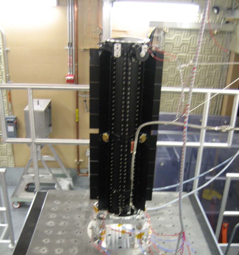
Vibration Testing of the Pluto/New Horizons
             Radioisotope Thermoelectric Generator

                                          Charles D. Griffin*
                          Idaho National Laboratory, Idaho Falls, Idaho, 83415

            The Radioisotope Thermoelectric Generator (RTG) for the Pluto/New Horizons
        spacecraft was subjected to a series of flight dynamic acceptance tests to
        demonstrate that it would perform successfully following launch. Seven RTGs of
        this type had been assembled and tested at Mound, Ohio, from 1984 to 1997. This
        paper chronicles major events in establishing a new vibration test laboratory at the
        Idaho National Laboratory and the dynamic testing during the Fall of 2005.

                                          I.    Introduction
    The spacecraft for the Pluto/New Horizons mission launched on January 19, 2006, is powered by a
General Purpose Heat Source Radioisotope Thermoelectric Generator (GPHS-RTG). The generator, the
eighth in a series of converters (F8), uses heat sources containing Plutonium-238 to provide the 250 watts
of electrical energy to power the on-board instrumentation. In 2002, the U.S. Department of Energy
decided to relocate assembly and testing activities of RTGs from Mound, Ohio, to Scoville, Idaho.
Following RTG assembly, a significant part of the flight acceptance tests involved subjecting the RTG to
random and transient vibration environments on each of its two principal axes to confirm the workmanship
of the assembly. Vibration testing for qualification of the design of the RTG had been completed over two
decades earlier in 1984.
    The task to establish a new vibration testing capability at the Idaho National Laboratory (INL) involved
three major efforts—removal and relocation of the equipment from Ohio to Idaho, installation and testing
of the equipment in the new facility, and testing of the F8 generator that would be used by the Pluto/New
Horizons spacecraft.

                                  II.    Removal and Relocation
     The task to remove and relocate the major pieces of equipment involved disconnection of electrical
cabling, cooling water lines, plant
instrument air lines, and hydraulic
hoses that interconnected the
equipment and Mound facility
utilities. For example, Fig. 1 shows
partial demolition at the base of the
vibrator: cut water hoses, hydraulic
fittings, yet to be removed air hoses,
and the plate where the armature and
field cables were disconnected. Ling
Dynamics Systems Inc. (LDS), the
original equipment manufacturer,
provided technical assistance during
the relocation and again during
installation in Idaho.

                                        Figure 1.   Demolished Vibrator Connections.

* Vibration Test Engineer, Radioisotope Power Systems, P. O. Box 1625/MS 6122, Idaho Falls, ID, 83415

                                                    1
                            American Institute of Aeronautics and Astronautics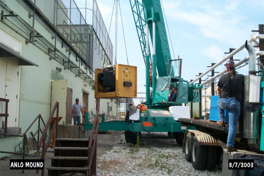
Figure 2. Vibrator Removal from Ohio.

   Figure 2 shows removal of the 19,000 lb vibrator from the old facility in Ohio, and Fig. 3 shows the lift
of when it was lowered through the roof of the new facility in Idaho eight months later.

                 Figure 3. Vibrator Installation in Idaho.

    As can be seen in the picture, the locating of major pieces of equipment occurred as the building was
being constructed around it. Three major system components were handled in this manner; the isolation
mass, vibrator, and slip table. The power amplifier, coupling transformer, and cooling unit/field power
supply came into the building through the truck lock roll-up doors.
    Construction was completed on the new Space and Security Power Systems Facility in July 2004, and
followed by equipment setup and installation to support disassembly and recovery of Pu-238 heat sources
for use in F8. During this period, the vibration equipment was installed in a parallel effort.

                                                    2
                            American Institute of Aeronautics and Astronautics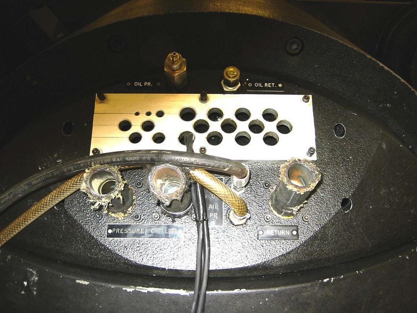
III.     Installation
    The vibration equipment relocated from Mound was vintage 1981 and had not been operated since
October 2002. During demolition, the LDS field service engineer recommended replacement of the slip
table hydraulic unit, cooling unit, and field coil power supply. Because of the uncertain condition of the
equipment, the vibration system engineer proceeded to:
         x Procure a new cooling unit/field power supply;
         x Repair and rebuild the slip table hydraulic unit;
         x Replace all tubing, fittings, hoses, and wiring;
         x Upgrade the controller and schedule training from the vendor, m+p International Inc.;
         x Send off the charge amplifiers, filters, accelerometers, and force transducers to their
             manufacturers for calibration and repair;. and
         x Arrange for preventive maintenance of the vibrator.
    Figure 4 shows removal of the vibrator top ring exposing the armature. The preventive maintenance

         Figure 4. Vibrator Maintenance.

quickly became corrective maintenance when it was discovered that the armature cooling and power
connections had corroded beyond use and the field coils exhibited evidence of overheating. A replacement
armature had to be obtained from Great Britain, but a set of new field coils were available in the U.S.
    Further mechanical problems presented themselves. The magnesium slip plate was sent off to a
machine shop in California to have scratches removed from the mounting surface. The company that made
the slip table in 1981 was no longer in business, and legacy parts had to be found to replace one of the three
hydraulic bearings and the six pins used to connect the X-K driver bar between the vibrator and slip table
that had been lost in the transfer of equipment from Ohio to Idaho.
    During system checkout, a transient input signal to the amplifier blew output fuses in all 36 power
modules. A sample of six modules returned to LDS for checkout indicated no damage to the modules
beyond the opened fuses. As a corrective action, the instrument and equipment grounds were checked and
upgraded. We also expedited delivery of the new controller and corrected (i.e., reduced) the maximum
output setting from the testing profiles that had been used in Ohio.
    We completed the installation, maintenance, and equipment testing in July of 2005.

                                                    3
                            American Institute of Aeronautics and Astronautics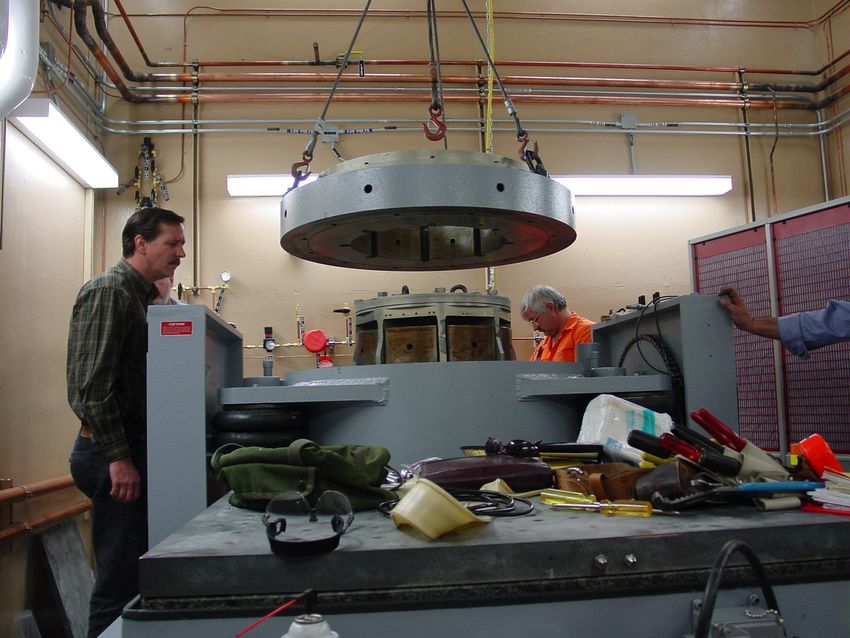
IV.     Testing
    Following F8 fueling, a set of voltage, current, and resistance measurements were collected to form the
pre-vibration test baseline power performance data. That data would again be collected post vibration
testing along with the response accelerometer measurements to demonstrate acceptable test results. The
vibration test sequence and environments are shown in Table 1.

                                                Table 1.
                                      Vibration Test Environments
          Test      Axis                       Environment                      Duration
                                               Sine Sweep
            1        Y                                                      2 octave per minute
                                 10-2000 Hz                          ½g
                                                Random
                                   20-72 Hz,                 +6 dB/octave
                                  72-180 Hz                   0.032 g2/Hz
                                 180-205 Hz                 -16 dB/octave
            2        Y           205-245 Hz                   0.016 g2/Hz    1 minute at 0 dB
                                 245-275 Hz                 +18 dB/octave
                                 275-450 Hz                   0.032 g2/Hz
                                450-2000 Hz                  -6 dB/octave
                                     Overall                    4.78 gRMS
                                                Transient
           3a        Y                                                        1 pulse at 0 dB
                                   15.75 Hz                         3.4 g
                                                Transient
           3b        Y                                                        1 pulse at 0 dB
                                    31.5 Hz                         3.4 g
                                                Transient
           3c        Y                                                        1 pulse at 0 dB
                                    50.0 Hz                         3.4 g
                                                Transient
           3d        Y                                                        1 pulse at 0 dB
                                   79.73 Hz                         3.4 g
                                               Sine Sweep
            4        Y                                                      2 octave per minute
                                 10-2000 Hz                          ½g
                                               Sine Sweep
            5         Z                                                     2 octave per minute
                                 10-2000 Hz                          ½g
                                                Random
                                   20-51 Hz                  +6 dB/octave
                                  51-176 Hz                   0.016 g2/Hz
                                 176-192 Hz                 -24 dB/octave
                                 192-240 Hz                   0.008 g2/Hz
            6         Z          240-256 Hz                 +10 dB/octave    1 minute at 0 dB
                                 256-352 Hz                    0.01 g2/Hz
                                 352-380 Hz                 +46 dB/octave
                                 380-450 Hz                   0.032 g2/Hz
                                450-2000 Hz                  -6 dB/octave
                                     Overall                    4.22 gRMS
                                                Transient
           7a        Z                                                        1 pulse at 0 dB
                                   15.75 Hz                         3.4 g
                                                Transient
           7b         Z                                                       1 pulse at 0 dB
                                    25.0 Hz                         3.4 g
                                                Transient
           7c        Z                                                        1 pulse at 0 dB
                                    63.0 Hz                         3.4 g
                                                Transient
           7d         Z                                                       1 pulse at 0 dB
                                   100.0 Hz                         3.4 g
                                               Sine Sweep
            8         Z                                                     2 octave per minute
                                 10-2000 Hz                          ½g

    During testing, the test team encountered several problems typical of vibration instrumentation and
equipment. There were six controller initiated aborts. Aborts during the sine sweeps resulted from an
inability to control the base accelerometers within 3 dB of the ½ g acceleration set point. The sine
sweeps were completed by expanding the control bounds to 6 dB at the high end of the frequency range.
Aborts during random testing resulted from noise and saturation of one of the response accelerometers at
frequencies above the test range. Filtering and amplifier and cabling changes fixed these problems.

                                                   4
                           American Institute of Aeronautics and Astronautics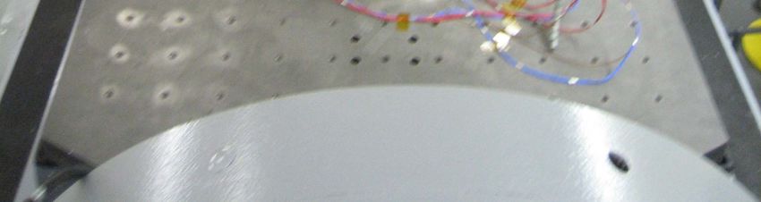
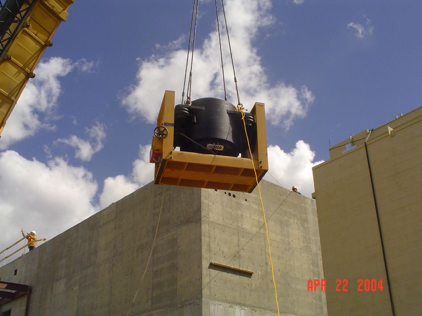
Figure 5 is a picture of the RTG mounted for y-axis
testing on the slip table. The vibrator, barely visible at the
bottom of the picture has been rotated to a horizontal
position and connected to the slip plate with the X-K driver
bar. Low-noise cables connect the accelerometers and force
transducers with the charge amplifiers and controller in the
next room.

                                V.     Conclusion
    F8 passed the flight acceptance vibration tests. There
was no damage or permanent distortion from the random
and transient tests as determined by comparisons of pre and
post test electrical performance data and because the
response accelerometer results were similar in the pre and
post test sine sweeps. For example, Fig. 6 is a comparison
plot of the ½ g Y-axis sine sweeps (tests 1 and 4) of the
accelerometer Y-axis responses for the feature on the
outboard end of the RTG known as the pressure relief
device.                                                            Figure 5. RTG Mounted for Y-axis Test.
    Note the three modes: the first at 48 Hz, the second at
220 Hz, and the third at 370 Hz. The response above 400
Hz reflects the difficulty in controlling the input applied to the RTG base caused by the mounting fixture.

                                                                                              Post Random
                                                                                              Sine Sweep

                                                                                              Pre Random
                                                                                              Sine Sweep
              Acceleraton (g)

                                                      Frequency (Hz)
                                Figure 6. Comparison of Y-axis Sine Sweep Tests.

                                                       Acknowledgments
    I would like to thank Curtis Albers of Ling Dynamic Systems Inc. and Jim Churchill of m+p
International Inc. for their expert assistance during equipment installation. I also thank Tim Hoye of
Lockheed Martin and Bill Bohne of the USDOE for bridging the Ohio to Idaho gap, and finally, Dennis
Hill of Lockheed Martin for being a dynamical dab hand.

  Work supported by the U.S. Department of Energy, Office of Nuclear Energy under DOE Idaho
Operations Office Contract DE-AC07-05ID14517.

                                                                 5
                                         American Institute of Aeronautics and Astronautics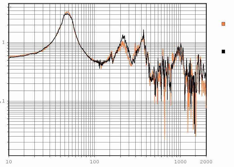
You can also read