WIFI-NC : WIFI OVER NARROW CHANNELS
←
→
Page content transcription
If your browser does not render page correctly, please read the page content below
WiFi-NC : WiFi Over Narrow Channels

            Krishna Chintalapudi⋆ , Bozidar Radunovic† , Vlad Balan‡ , Michael Buettener§ ,
                  Srinivas Yerramalli‡ , Vishnu Navda⋆ , and Ramachandran Ramjee⋆
     ⋆
         Microsoft Research India; † Microsoft Research UK; ‡ USC; §University of Washington

ABSTRACT                                                              For example, a device must be able to use (transmit/receive
The quest for higher data rates in WiFi is leading to the de-         on) eight 5 MHz channels instead of one 40 MHz channel.
velopment of standards that make use of wide channels (e.g.,          This diametrically opposite view is designed to address the
40MHz in 802.11n and 80MHz in 802.11ac). In this paper,               following three key inefficiencies of current single (wide)
we argue against this trend of using wider channels, and in-          channel systems (Section 3).
stead advocate that radios should communicate over multi-                First, inefficiencies arise when heterogeneous radios co-
ple narrow channels for efficient and fair spectrum utiliza-          exist. While WiFi is designed to be fair to devices oper-
tion. We propose WiFi-NC, a novel PHY-MAC design that                 ating in the same channel, operation of 40 MHz devices
allows radios to use WiFi over multiple narrow channels si-           near 20 MHz devices leads to starvation [1]. Consequently,
multaneously. To enable WiFi-NC, we have developed the                802.11n standard mandates devices to reduce their channel
compound radio, a single wideband radio that exposes the              width to 20 MHz immediately upon detecting any coexist-
abstraction of multiple narrow channel radios, each with in-          ing 20 MHz device. As a result, in practical 802.11b/g/n
dependent transmission, reception and carrier sensing capa-           deployments, 802.11n devices are often relegated to using
bilities. The architecture of WiFi-NC makes it especially             only 20 MHz channels. To the best of our knowledge, no
suitable for use in white spaces where free spectrum may              work has addressed this practical and common inefficiency
be fragmented. Thus, we also develop a frequency band se-             in WiFi, which is bound to only get worse as 802.11ac de-
lection algorithm for WiFi-NC making it suitable for use in           vices with 80 MHz radios become available. In contrast, a
white spaces. WiFi-NC has been implemented on an FPGA-                40/80 MHz WiFi-NC radio configured with two/four 20 MHz
based software defined radio platform. Through real exper-            channels can make full use of its 40/80 MHz radio while still
iments and simulations, we demonstrate that WiFi-NC pro-              coexisting fairly with other 20/40 MHz networks.
vides better efficiency and fairness in both common WiFi as              Second, it is well-known that, due to MAC overheads such
well as future white space scenarios.                                 as backoffs, the increase in PHY data rates does not trans-
                                                                      late to commensurate gains in TCP/UDP throughput [22,
                                                                      17]. To address this inefficiency, 802.11n standards support
1.   INTRODUCTION                                                     MAC-layer frame aggregation that allow frame sizes of up
   Over the past decade, WiFi data rates have seen over a             to 64KB, thereby reducing the relative impact of the MAC
100x increase. This was achieved through advances in phys-            overhead. While frame aggregation works well for bulk data
ical layer wireless communication techniques (e.g.,OFDM,              flows, other traffic such as TCP acks, VoIP packets and short
64 QAM and MIMO) that provided increased spectral effi-               HTTP flows are not amenable to such aggregation. The use
ciency (bits/s/Hz). As further improvements in spectral ef-           of narrow channels in WiFi effectively also elongates packet
ficiency become harder to achieve, using wider channels is            transmission times relative to MAC overhead (for a given
being viewed as a solution to attain higher data rates. To-           frame size, transmission time doubles when channel width
day, 802.11n already allows for 40 MHz channels while the             is halved), thereby achieving higher throughput.
upcoming 802.11ac proposes 80 and 160 MHz channels.                      Third, fragmented spectrum can result in inefficient usage.
   In this paper we argue against this obvious approach of            For example, WhiteFi [4] uses variable width channels for
merely increasing the channel width to increase wireless data         operation in fragmented white spaces. However, the restric-
rates. Instead, we espouse the opposite – that the channels           tion of being able to use a single channel (wide or narrow) at
be no wider than existing 20 MHz WiFi channels and ideally            a time, limits WhiteFi’s ability to efficiently use free parts of
be narrower, say 5 MHz or even 2 MHz. In order to achieve             the spectrum. For example, two 6 MHz narrow channels of a
higher data rates then, unlike current day devices that operate       WiFi-NC radio can operate simultaneously on either side of
over only one channel at a time, we propose WiFi-NC a novel           a 6 MHz operating TV channel, while a single-channel sys-
physical and MAC design that allows devices to run WiFi on            tem like WhiteFi will be restricted to choosing only one of
several narrow channels, simultaneously and independently.

                                                                  1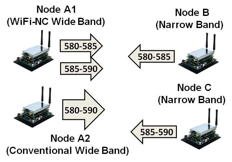
the two bands. The ability to use multiple narrow channels              WiFi-NC stays the same as in WiFi while employing cross-
simultaneously, allows us to devise an optimal throughput               correlation over the dilated preamble in parallel for OFDM
maximizing spectrum selection scheme, T M ax, that is not               frame synchronization and frequency offset estimation.
possible in single channel systems.                                        We have prototyped the compound radio and WiFi-NC
   Related work that comes closest to WiFi-NC is FICA [22].             on a FPGA-based software defined radio platform. Through
FICA splits a single OFDM physical channel into narrower                both real experiments on our testbed (Section 8) as well as
sub-channels and allows different devices to access them.               extensive simulations (Section 9), we show that WiFi-NC is
However, sub-channels differ from narrow channels in a very             both more efficient and fair than WiFi. Further, while op-
fundamental way – in FICA, a new transmission opportunity               erating in white spaces, we show that WiFi-NC is able to
arises only when the entire wide channel is idle; then, trans-          achieve up to 121% higher throughput than WhiteFi [4] in
missions by devices over different sub-channels are tightly             the presence of background transmitters.
time synchronized (≈ 10µs) Thus, FICA is essentially a                     While the use of narrow channels has significant efficiency
wide single-channel system with sub-channels that are inter-            benefits, the primary cost is increased logic/memory require-
dependent. While FICA addresses the MAC inefficiency is-                ments both at the transmitter/receiver (e.g., transmit and re-
sue, the lack of independence among sub-channels precludes              ceiver filters, decoding logic per narrow channel, etc.). How-
FICA from solving the inefficiencies due to heterogeneous               ever, as the FPGA/ASIC sizes grow benefiting from Moore’s
radio co-existence or fragmented spectrum.                              law, we believe that the additional logic/memory require-
   The centerpiece of WiFi-NC is the compound radio, a                  ments will not pose a significant constraint.
novel design, that uses a single physical wideband radio but               In summary, our paper makes three key contributions:
provides the abstraction of several independent narrow band               • The simple insight that radios with multiple independent
radios – radiolets, to the MAC layer. Each radiolet allows                  narrow channels instead of a single wide channel can im-
for independent carrier sensing, transmission and reception                 prove the efficiency of WiFi in many practical settings
of packets in its own narrow channel. Radiolets are entirely                such as heterogenous radio co-existence, at high PHY
implemented as digital circuits and provide the low cost and                speeds and operation in fragmented white spaces.
form factor benefits of digital processing.
                                                                          • WiFi-NC, a novel PHY-MAC design that operates WiFi
   The fundamental challenge in designing a compound ra-
                                                                            independently over multiple narrow channels, and its im-
dio is enabling efficient interference isolation among the ra-
                                                                            plementation in the form of a compound radio on a FPGA-
diolets – a compound radio must be able to simultaneously
                                                                            based software defined radio platform.
carrier sense, receive, and transmit over different radio-lets
without any inter-dependence. Note that, even if conven-                 • T M ax algorithm for maximizing throughput by opti-
tional radios supported full duplex communication [7, 12,                  mal frequency selection for WiFi-NC radios operating
19] over wide bands, we cannot simply divide the full du-                  in white spaces.
plex wide channel into multiple full duplex narrow chan-
nels and independently transmit/receive over these narrow               2. RELATED WORK
channels. This is because while a full duplex radio will can-
cel out the spectral leakage of the narrow channel OFDM                    There has been tremendous amount of work targeted to-
transmission at the transmitter, the spectral leakage can still         wards improving WiFi and wireless communication. We dis-
cause severe degradation in adjacent narrow channels at the             cuss a few papers that are most relevant to WiFi-NC here.
receiver (since the narrow channels are not synchronized).                 Performance. A number of papers [13, 15, 20, 22] have
Thus, in order to achieve channel isolation, the compound               proposed novel techniques to improve WiFi performance.
radio uses sharp elliptic filters at both the transmitter and re-          FICA [22] is closest to WiFi-NC in terms of advocating
ceiver (Section 5). These filters allows us to use very narrow          for fine-grain access. However, FICA proposes the use of
guard bands between the radiolets (100KHz in our imple-                 subchannels for fine-grain access which is fundamentally
mentation), thereby paying an overhead of only 5% or 2%                 different from the narrow channels of WiFi-NC. Subchan-
for a 2 MHz or 5 MHz narrow channel, respectively.                      nels in FICA require a synchronous system, where all nodes
   Another fundamental effect of using narrow channels is               in carrier sense range must transmit within a few microsec-
the need for preamble dilation. Since narrow channels trans-            onds of each other. While it may be possible to time/frequency
mit information at a slower rate, PHY layer preambles take              synchronize all APs under one management, FICA will not
longer to transmit. While the longer preamble results in only           perform well in practical settings where WiFi APs from sev-
a small overhead for WiFi-NC (because data transmission                 eral autonomous systems (businesses/homes) co-exist and
times also dilate), a bigger issue is if this dilation results in       are not time/frequency synchronized. Furthermore, even with
increased carrier sensing time – in this case, WiFi-NC would            time/frequency sychronization, FICA does not tackle the in-
need larger slots, which will severely affect channel utiliza-          efficiencies that arise due to radios with different channel
tion [17]. In order to avoid this problem, the compound ra-             widths or operation in fragmented spectrum.
dio uses energy detection to ensure carrier sensing time in                Coexistence. SWIFT [21] tackles the problem of coexis-
                                                                        tence of wide band radios in the presence of narrow band de-

                                                                    2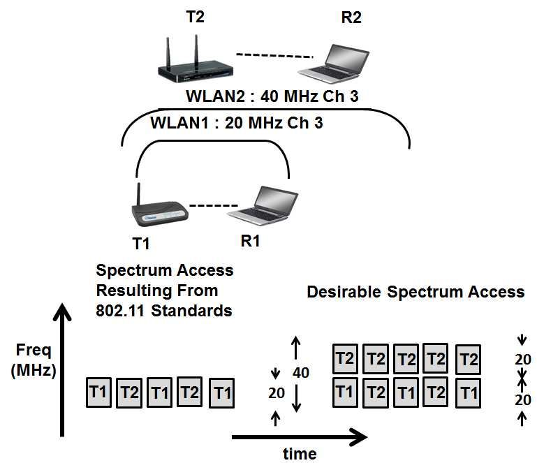
vices. The SWIFT radio detects narrow band transmissions                 White spaces. Closest to WiFi-NC is WhiteFi [4], a WiFi-
and then weaves together the unused (non-contiguous) bands            like system for TV white spaces. WhiteFi includes a spec-
into one wireless link by transmitting only on the unoccu-            trum assignment algorithm that maximizes a multichannel
pied frequencies. While both WiFi-NC and SWIFT support                airtime metric called MCham and an algorithm called SIFT
non-contiguous operation, SWIFT still uses the entire avail-          for detecting APs of varying channel widths. While WhiteFi
able, and potentially wide, band as a single channel, thus,           supports variable channel width access, WhiteFi only sup-
suffering the same inefficiencies as WiFi.                            ports contiguous operation over the channel. As we shall
   Variable Channel Width. The use of 5 or 10 MHz chan-               see in Section 7, the contiguous access restriction results
nels can increase range and reduce power consumption [5].             in efficiency loss due to coexistence as well as due to the
However, the channel width adaptation in previous work [5]            conservative behavior of the MCham metric. Since WiFi-
only configures the radio to one of 5, 10, 20 or 40MHz                NC supports independent narrow channels, non-contiguous
channel for a single communicating pair of radios. Coexis-            operation through suppression of one or more narrow chan-
tence/fairness will be an issue if multiple networks are con-         nels provides significant efficiency benefits when operating
figured with different channel widths. In WiFi-NC, each ra-           in fragmented white space spectrum. Authors in [24] pro-
dio can choose to use one or more independent narrow chan-            pose Jello, a per-session FDMA system for latency sensitive
nels, thus, gaining the benefits of narrow channels without           applications such as streaming media. The focus is on uti-
sacrificing coexistence.                                              lizing (non-contiguous) white space spectrum over session
   Guard bands. A number of techniques to mitigate the                durations rather than on a per-packet basis as in WiFi-NC. In
problem of adjacent channel interference was studied in [11].         addition, Jello does not consider fairness among distributed
The authors found that the use of guard bands was the most            nodes, a key feature of WiFi-NC.
efficient solution to the problem. The issue of appropriate
size for the design of guard bands was considered in [25].            3. MOTIVATION FOR WIFI-NC
The authors show that the size of guard band needs to be
adapted based on the location of the wireless nodes. How-                Existing wideband radios are monolithic, and access the
ever, the software digital filters used in [24, 25] were Ham-         channel in an "all-or-none" fashion. This design is ineffi-
ming window filters that do not have the sharp cutoff proper-         cient in multiple settings and also leads to unfair channel ac-
ties of the elliptic filters used in WiFi-NC (Section 5). Thus,       cess. We highlight these inefficiency and unfairness issues
we are able to show that even a small fixed guard band is             by using three examples.
conservative enough for our needs. Moreover, a system like            Example 1 - Heterogeneous Radios: Inefficiency in Fre-
Ganache [25] can also help adapt the guard band size in               quency. Consider the concurrent operation of two WLANs
WiFi-NC dynamically.                                                  (Figure 1a) – an 802.11g WLAN1 (transmitter T1, receiver
   Full-duplex. Recently, full-duplex single channel wire-            R1) operating on 20 MHz channel 3 and an 802.11n WLAN2
less communication systems have been proposed [7, 12, 19].            (T2, R2) operating on 40 MHz channel 3. As dictated by
The key challenge in these systems is eliminating the self-           the 802.11n standard, the 802.11n radio detects the 20MHz
interference of the local transmitter. Note that, if these sys-       transmitter and reconfigures itself to only operate on the 20MHz
tems operate over the standard 20MHz WiFi channel, they               channel 3 (In fact, we were unable to get our 802.11n radio
would also suffer the same MAC overhead inefficiencies as             to operate in 40MHz mode in any of 2.4GHz channels in
WiFi. Full-duplex communication is an orthogonal feature              our lab due to this reason). Thus, transmitters T1 and T2 al-
to WiFi-NC and can be added to the narrow channels of                 ternatively use the 20MHz band while 20MHz of frequency
WiFi-NC.                                                              remains completely unused.
   Fairness. 802.11-based wireless networks exhibit unfair-              The above 802.11n mandate was a result of the obser-
ness due to a number of reasons including hidden termi-               vation that operation of 40 MHz 802.11n pre-standard de-
nals [8], capture effect [16], exponential backoffs (short term       vices (not subject to the above mandate) alongside 20 MHz
unfairness) [9], etc. WiFi-NC is focused on the problem of            802.11g devices led to extreme unfairness and even star-
unfairness that arises when two or more networks operate              vation. To understand the reason for this unfairness con-
over frequency bands that overlap (Section 3).                        sider the concurrent operation of three WLANs (Figure 1b) -
   Overlapping Channels. Authors in [3] show significant              WLAN1 (transmitter T1, receiver R1 ), operating on 20MHz
unfairness in chaotic WiFi deployments where WiFi chan-               Channel 6; WLAN2 (T2, R2) operating on 20 MHz channel
nels of adjacent access points can overlap and argue that bet-        11; and WLAN3 (T3, R3) operating on 20 MHz channel 9.
ter channel allocation and power control can help improve             Since T3 is able to carrier sense both T1 and T2, 802.11
efficiency and fairness. Similarly, authors in [18] propose           based CSMA dictates that it must wait until both T1 and
a frequency hopping algorithm called MAXchop for avoid-               T2 are not transmitting. However, T1 and T2 do not inter-
ing unfairness in uncoordinated deployments. Compared to              fere with each other and may transmit whenever T3 is not
these approaches, the narrow channel model of WiFi-NC re-             transmitting. As depicted in Figure 1b, whenever T1 finishes
duces the possibility of partial overlap in channels.                 transmitting a packet, T2 is still transmitting and vice-versa.
                                                                      Thus, T3 never finds its channel free for transmission result-

                                                                  3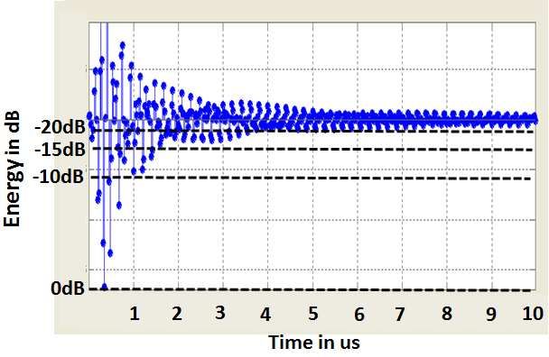
(a) Example I                               (b) Example I (partial overlapping)               (c) Example II

                                                                                              1: Examples
                                                                                                        An alternate approach that increases efficiency but does not
                                 40
                                                                                                        require larger frame sizes is simply the use of narrow chan-
                                 35
                                          Channel-6                                                     nels. As seen in the Figure, reducing channel width from
         TCP Throughput (Mbps)

                                 30
                                          Channel-9                                                     20MHz to 5MHz simply results in quadrupling of the packet
                                          Channel 11
                                 25                                                                     transmission time (the MAC overheads don’t change). Thus,
                                          Aggregate
                                 20                                                                     by elongating packet transmission time, narrow channels are
                                 15                                                                     able to better amortize the MAC time overheads.
                                 10                                                                        Note that there is a new inefficiency introduced due to nar-
                                 5                                                                      row channels, namely, the guard band or the gap between
                                 0                                                                      two 5MHz channels. We show how this overhead can be
                                      1 Active Link    2 Active Links   3 Active Links
                                                                                                        kept very small (2% for 5MHz channels) in Section 5.
       2: Unfairness due to partial channel overlap                                                     Example 3 - Fragmented Spectrum: The recent FCC rul-
                                                                                                        ing of T.V white spaces allows secondary devices to trans-
                                                                                                        mit in parts of the spectrum unoccupied by primary trans-
ing in its starvation.                                                                                  mitters such as T.V broadcasts operating over 6 MHz chan-
   The above starvation effect also manifests itself when WiFi                                          nels. Such an opportunistic scenario often requires devices
devices operate over overlapping 20MHz channels. To demon-                                              to operate in a fragmented spectrum. Consequently, a white
strate this effect in a practical setting, we setup three iden-                                         space device with 40 MHz radio bandwidth may not find
tical 802.11b/g Netgear APs inside a lab area, and we had                                               even a single continuous span of 40 MHz. A device that al-
one client associated with each AP. The APs are configured                                              lows independent channel access and communication over
to operate in channels 6, 9 and 11. The Figure 2 shows av-                                              several narrow channels (say, eight 5 MHz channels) will al-
erage TCP throughput at the clients for three different set-                                            low the use of fragmented spectrum more efficiently since
tings: (1) only one client is downloading at any time, (2)                                              the white space device can simply transmit around any oc-
two clients R1 and R2 on non-overlapping channels, 6 and                                                cupied T.V. Channels. This example shows that the future
11, downloading, and (3) all three clients are simultaneously                                           white space devices need to support non-contiguous oper-
downloading. From (1) and (2), it is clear that TCP flows on                                            ation which comes naturally to a device that has multiple
channel 6 and 11 are independent and do not interfere with                                              independent narrow channels.
each other when operating simultaneously. However, when
all three flows are active, the client on channel 9 receives al-
most negligible throughput (570Kbps) compared to the other                                              4. WIFI-NC
two clients (20 Mbps each) as depicted in case (3).                                                        In section 3 we saw that devices can achieve fairness, in-
Example 2 - MAC Overhead: Inefficiency in Time. An-                                                     creased efficiency and can potentially better use fragmented
other source of well-known inefficiency [22], illustrated in                                            spectrum if they used multiple independent narrow channels
Figure 1c, arises from the fact that as the device bandwidth                                            instead of a single wide channel. Given that WiFi already
increases, while the time to transmit packets becomes smaller,                                          provides fair access to devices operating in the same chan-
the MAC overheads such as carrier sense and backoffs re-                                                nel (narrow or wide) through CSMA and backoff, WiFi-NC
main constant. 802.11n attempts to combat this unfairness                                               simply allows devices to operate WiFi independently over
by allowing for aggregated frames up to 64KB in size but                                                multiple narrow channels.
this requires delaying frames at the interface in order to ag-                                             Figure 3 shows an illustration of WiFi-NC node config-
gregate a large number of smaller packets and is not suitable                                           ured with four 5MHz narrow channels using a 20MHz radio.
for applications such as VOIP or short HTTP transactions.                                               The WiFi-NC MAC maintains independent random backoff

                                                                                                    4
time synchronized. This is because in OFDM, sub-carriers
                                                                      overlap with each other and their accurate spacing and time
                                                                      synchronization is key to enable decoding at the receiver.
                                                                      Consequently, independent CCA, transmission and recep-
                                                                      tion over sub-channels is not possible and leads to the same
                                                                      inefficiencies in co-existence between narrow and wideband
                                                                      devices described in Section 3.
                                                                      Our Approach - Compound Radio. In order to enable mul-
                                                                      tiple narrow channels, we propose a novel PHY-MAC design
                                                                      – the compound radio. The compound radio, while using
      3:   WiFi NC implements WiFi over several narrow channels       a single wideband physical radio device, performs digital
                                                                      processing to provide the abstraction of multiple indepen-
                                                                      dent radios to the MAC layer. This is achieved by perform-
counters and performs carrier sensing on each narrow chan-            ing channelization digitally through digital filters and digital
nel. Whenever the backoff counter expires for a given nar-            mixers as described in Section 5. Since digital filters allow
row channel, a packet from the transmit queue is transmit-            for extremely cheap and high performance filters in com-
ted over the corresponding narrow channel. Similarly, pack-           parison to analogue filters, digitally implemented adjacent
ets can be received independently over narrow channels and            channels require “very thin” guard bands (100 KHz in our
placed in the receive queue. As can be seen from the Figure,          implementation). Further, unlike overlapping sub-carriers in
the narrow channels are completely independent from each              OFDM, these channels are completely separate from each
other. Thus, transmissions can be on-going simultaneously             other and have absolutely no cross-talk among them, allow-
to different receivers (e.g., transmission to device 1 and 2),        ing complete independent operation.
while other narrow channels can be in reception or carrier
sensing mode. As we show in our evaluations (Section 9),
this key property of independent narrow channels help WiFi-           5. COMPOUND RADIO ARCHITECTURE
NC significantly outperform WiFi in terms of both efficiency             As discussed in Section 4, the compound radio provides
and fairness in many common scenarios.                                an abstraction of multiple narrow-band radios while using
                                                                      only a single physical wideband radio. In this section, we
4.1 Exploring Design Choices                                          start by describing the functioning of a conventional OFDM
   Off-the shelf radios allow operation on only one channel           radio focusing only on the components that are necessary for
at time. In order to implement WiFi-NC there are several              providing the required background and then follow with our
different alternatives. In this section, we consider these al-        proposed architecture for the compound radio.
ternatives.
Use multiple narrowband radios on the same device. Sev-               5.1 A Conventional Radio
eral papers have advocated the use of multiple radios on                 As depicted in Figure 4 a typical radio transmitter or re-
a single node for better performance [2, 14]. Thus, one               ceiver consists of two key parts - an analogue front end and
could consider implementing WiFi-NC using multiple nar-               the digital baseband. Almost all the complex physical layer
row band radios. However, apart from several practical short-         packet processing such as MIMO, OFDM, encoding and de-
comings such as cost, form factor, etc., there is also a funda-       coding etc. are implemented in the digital baseband since
mental drawback with such an approach – isolation require-            digital circuits provide the benefits of low cost, form factor
ment in the form of large guard bands between radios. For             and ease of implementation. However, as it is hard to design
example, WiFi radios use a guardband of 3 MHz between                 cheap digital circuits at clock rates of several GHz, the sig-
two adjacent channels for interference free operation. This           nal must first be down-converted from the carrier frequency
means that in order to create a compound radio of 80MHz               (2.4/5 GHz) to the baseband frequency (20 MHz in case of
with four 20 MHz radios, one would require guardbands                 20 MHz channels) using the analogue frontend.
worth 15 MHz (three 3 MHz in between the four radios and              Analogue Transmit and Receive Filters. In order to avoid
two on either side) - reducing spectral efficiency to 80%.            interference from/to devices operating over adjacent chan-
This loss of spectral efficiency is further exacerbated as one        nels, radios use transmit and receive filters in the analogue
uses narrower channels, say, 5MHz wide.                               front end (Figure 4). These filters, only let frequencies within
Use the sub-carrier structure of OFDM itself to enable                the bandwidth of the channel to pass through (say 2.4-2.42
fine-grain access. Prior work such as FICA [22] suggests              GHz for 20 MHz channel 1).
that different nodes may use different sub-carriers within the        Mixer. The mixer, at the receiver, is responsible for down-
same underlying physical channel to create sub-channels.              converting the received signal at carrier frequency (2.4 GHz)
However, in this approach actions such as Clear Channel               to baseband frequencies (0-20 MHz) to be presented to the
Assessment (CCA), transmission and reception performed                digital baseband. At the transmitter, it up-converts the base-
by different devices across all sub-channels must be tightly          band signal to carrier frequency making it suitable for trans-

                                                                  5
4: Conventional Radio and Compound Radio
mission. of subcarriers intended for the wide band channel. Second,
ADC and DAC. These are used to convert between the ana- it operates at N1 the sampling frequency of that used for the
logue signal at baseband frequencies to digital signal at the wideband radio, since the required Nyquist sampling rate for
receiver and vice-versa at the transmitter. the narrow channel is N1 of that for the wide channel with
AGC. Typical DAC circuits are designed to operate correctly bandwidth B. As discussed later in this section, this allows
for a specific input voltage range (say 0.5V to -0.5V). Thus, individual transmitterlets to operate at N1 the clock rate and
Automatic Gain Control (AGC) appropriately scales the ana- hence keep the total number of operations required per sec-
logue signal from the antenna to ensure that the signal from ond across the N transmitterlets the same as the wide band
the antenna is within the desired voltage range. radio.
Baseband transmitter/recevier. Generation and reception Upsampler. In order to match the sampling rate of the wide
of packet including MIMO, OFDM, encoding, decoding, mod- band radio, the digital samples from the baseband transmit-
ulation and demodulation are handled by the baseband trans- ter are upsampled by a factor of N . During upsampling,
mitter and receiver using digital circuits. N − 1 additional digital samples are inserted between two
consecutive samples through interpolation. There are sev-
5.2 A Compound Radio eral ways to interpolate – in our implementation, we use a
The key idea behind the compound radio architecture is DFT based upsampler.
to use digital mixers and transmit/receive filters in the base- Low Pass Filter. A sharp low pass filter (described in detail
band to create narrow channels digitally. Figure 4 depicts later in the section), ensures that the signal is indeed limited
B
this idea for a compound radio that implements four 5 MHz to within 0 to N MHz.
narrow channels. Mixer. Prior to the mixer, the digital signals in all trans-
B
mitterlets have frequencies between 0 - N MHz. The dig-
5.2.1 Compound Transmitter th
ital mixer for the k transmitterlet shifts these frequencies
The compound transmitter comprises N transmitterlets, by (k−1)B
N MHz to ensure that the digital signal emanating
each responsible for transmitting data over one narrow chan-
B
from it has frequencies in the range ( (k−1)B
N , kB
N ) MHz. The
nel of width N , where B is the bandwidth of the analogue mixer essentially multiplies each digital sample by a com-
front end. Each transmitterlet consists of a baseband trans- plex sinusoid of frequency (k−1)B MHz and can be cheaply
N
mitter, an upsampler, a digital low pass filter and a digital implemented using a ROM and two digital multipliers.
mixer. The outputs of each of the transmitterlets are then
added digitally and passed on to the analogue frontend which
is identical to the analogue frontend of a conventional radio. 5.2.2 Compound Receiver
Baseband Transmitter. The baseband transmitter is iden- The compound receiver architecture is symmetric to that
tical to the baseband transmitter used in any conventional of a compound transmitter and consists of multiple receiver-
radio, except for two differences. First, since it operates lets - each to receive packets over one narrow channel. Each
over a channel that is N1 the bandwidth, it uses N1 number receiverlet comprises, a mixer, a low pass filter, a down sam-
6pler and finally the baseband receiver. The mixer of the k th Filter Type Bandwidth 5 MHz Bandwidth 2 MHz
# Adds # Mults # Adds # Mults
receiverlet downs shifts the frequency of the received signal Chebyshev 76 76 48 48
by (k−1)B
N MHz. This frequency downshifting ensures that Butterworth
Elliptic
492
26
492
20
208
22
208
17
frequencies corresponding to the k th receiverlet i.e., in the
range ( (k−1)B
N , kB
N ) MHz are mapped to the range (0, N )
B
1: Filter Comparison - 60dB attenuation, 100KHz guard-
MHz. A low pass filter between (0, B) MHz then extracts band
on the band corresponding to the receiverlet. A N1 down-
sampler then reduces the sampling rate by a factor of N1 by
simply dropping N − 1 consecutive samples after picking and receive filters that provide an attenuation of about 60 dB
each sample. The baseband receiver is identical to the base- within 100kHz. Note that this represents an extreme scenario
band receiver of a conventional radio except that it operates for WiFi-NC where the self-interference is maximum com-
at N1 the sampling rate and uses N1 sub-carriers of that used pared to the received signal.
for the wideband channel. Table 1 shows the number of adders and multipliers re-
quired to achieve our design (100 KHz guardband, 60 dB
6. DESIGN CHALLENGES attenuation) by different choices of filters. As indicated in
Table 1, Elliptic Filters [10] satisfy our requirements with
We faced two fundamental challenges in the design of the
the least number of elements. Consequently, we use Elliptic
compound radio.
filters in our implementation.
Interference Isolation. In WiFi-NC, nodes must be able
We have implemented the compound radio on an FPGA
to carrier sense, receive and transmit simultaneously on adja-
based software defined radio platform (Section 8). Figure 6
cent narrow channels. Since we use OFDM in each narrow
depicts the transmitted spectrum measured at a distance of
channel for efficiency, the leakage from OFDM transmis-
1cm from the transmit antenna for a 16QAM, 3/4 coding (36
sions into the adjacent narrow channels can be significant
Mbps) OFDM transmission over a 5 MHz narrow channel.
(Section 6.1). We need to be able to isolate this interference
As seen from Figure 6, the spectral leakage due to OFDM is
within each narrow channel.
significantly high and decays to only about -60dBm even at
Preamble Dilation. While the use of narrower channels
a distance of 2MHz from the transmitted band. The figure
increases efficiency in WiFi-NC, channel widths below 20 MHz
also shows the spectrum when using our transmit filter. We
can lead to inefficiencies from increase in physical layer pream-
can see that the spectrum decays to about -90dBm beyond
ble lengths since narrow channels inherently transmit infor-
the 100 KHz guard band.
mation at a lower rate.
In the rest of this section, we describe in detail each of
these challenges and the approach we use to address them.
6.1.1 Effect of Carrier Frequency Offsets
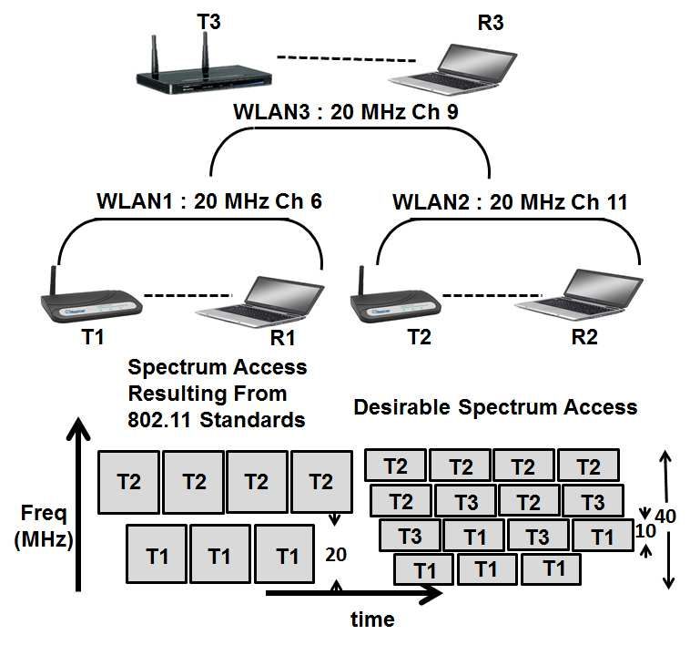
6.1 Interference Isolation Due to manufacturing variations, two different radios in-
Figure 5 depicts a possible scenario with three WiFi-NC variably have a carrier frequency offset (CFO) - small dif-
nodes. Node A simultaneously transmits to nodes B and C ference in their carrier frequencies. These differences im-
over narrow channels 1 and 3. At the same time nodes B and ply that the channel boundaries of two communicating ra-
C transmit to node A over narrow channels 2 and 4 respec- dios will not be exactly aligned. This misalignment places
tively. The spectrum of each of these transmissions as seen a practical lower limit on how narrow guardbands can be in
at Node A is also depicted in Figure 5 – node A’s receiver ex- WiFi-NC since using guardbands smaller than the CFO will
periences very high interference from its own transmissions lead to interference leakage into adjacent narrow channels.
in narrow channels 1 and 3 (about -20 dBm at the receive The 802.11 standard requires CFO for any two pair of radios
antenna, assuming a transmit power of 20 dBm [12]). Node to be under 25ppm (60 KHz) in the 2.4 GHz band and un-
B and C are located far away and their signals at A are ex- der 20ppm (116 KHz) in the 5.8 GHz band. CFO for white
tremely weak, about -85 dBm and -80 dBm, respectively. space devices operating in the 200-800 MHz will be under
Let as assume that we limit guard bands between nar- 20 KHz (assuming 25ppm). Our choice of 100KHz guard-
row channels to 100 KHz so that even for a 2 MHz narrow band, thus, accommodates CFO in both white spaces as well
channel, spectral wastage is only 5%. Figure 5 also depicts as at 2.4 GHz in 802.11. In the 5.8 GHz band, however,
the typical OFDM spectral leakage in the absence of filters. a slightly larger guardband, perhaps 150 KHz wide, maybe
The power in the adjacent channels decays to approximately required. In practice, since manufacturers typically ensure
about -40 dBm in the adjacent channels. In order to pro- that the CFO is safely below the maximum allowed limit,
vide perfect interference isolation, the transmit and receive we believe that CFO will not be an issue for WiFi-NC.
filters must attenuate the OFDM spectral leakage to below
noise levels (-90 dBm or lower). Thus, we require an attenu- 6.1.2 Effect of limited bits in ADC
ation of the transmit signal by least 50dB to provide interfer- While one can achieve self-interference isolation only by
ence isolation. Thus, in our implementation, we use transmit using sharp filters, this is possible only if the ADC of the
75: A possible scenario in WiFi-NC
6: Spectrum of transmission with and without filters
radio is able to support a wide range of power levels. An
ADC typically accepts as input an analogue signal that is
within ±0.5 V (or a similar range). Consequently, received
signal is typically scaled (by a gain controller) down (or up)
to lie within this range. The range of an ADC is specified in
bits. Each extra bit of the ADC allows for discerning signals
with half the amplitude and hence one fourth the power – in
other words, each bit provides 6 dB resolution.
Since our testbed platform uses 14 bit ADCs, it has a
range of 84 dB which means the radio is sensitive to sig-
nals that are 84 dB below the strongest received signal. In
the face of -20dBm self interference then, a weak signal that
is -85dBm effects only the last three to four bits of the ADC 7: Filter induced multipath
but is still discernible. However, many commercial systems
use ADCs with 9 to 12 bits. Thus, for an ADC with 10 bits
(60 dB range), this signal cannot be discerned at all since the digital sample through the filter. As seen from the figure, the
last bit corresponds to -80dBm. filter spreads the sample for several microseconds in time.
In devices with fewer ADC bits, analogue self-interference This spreading in fact is the same effect as spreading due
cancelation [19] or signal-inversion using Balun transformer [12] to indoor multipath environments. Such spreading results
can be used to reduce the strength of self-interference so that in self-interference between symbols termed Inter Symbol
power levels are in the range of the ADC. For example even Interference (ISI).
a reduction of self-interference power by 25dB provided by Need for longer Cyclic prefix (CP). In order to combat ISI,
Quellan QHx220 noise cancelers used in [19] or the 45dB OFDM uses the cyclic prefix, which pre-appends 25% of the
over 40 MHz provided by Balun transformers [12] will per- OFDM symbol and extends the symbol. The spread version
mit devices with 9 bit ADCs to receive weak signals at -85 of the previous symbol, thus interferes with the cyclic pre-
dBm while transmitting on adjacent channels. fix and does not adversely effect the original symbol. Typ-
Note that this cancelation is distinct from cancelation needed ical spreading due to multipath in indoor environments is
in full duplex systems [7, 19] – the cancelation here merely less than 800 ns, consequently, WiFi uses 800 ns cyclic pre-
helps bring the power levels within the range of ADC so that fix. However, use of sharp filters in the compound radio in-
transmit and receive can operate on separate channels while creases this spreading. As seen in Figure 7, the spreading de-
full duplex systems require cancelation of the full transmit cays by about 10dB within 800 ns and to about 15 dB within
signal so that one can receive on the same channel. 1.6µs. While low data rate modulations such as BPSK re-
quire about 6 dB SNR, higher data rate modulations such as
6.1.3 Filter Induced Interference 16 QAM may require up to 14 dB SNR. In our implementa-
A filter restricts the spectrum of the signal by spreading tion we found that a cyclic prefix about 1.6µs long allowed
(smoothing) it in time. The sharper the filter, the more the for successful reception even at higher data rate modulation
spreading. Figure 7 depicts the impulse response of our filter such as 16 QAM.
i.e., the transmitted signal resulting from passing a single Increasing Number of Subcarriers. Cyclic prefix is a waste-
8ful part of the transmission and results in a decrease in spec- How much does the preamble dilate for WiFi-NC?
tral efficiency. In order to keep efficiency the same after ex- The pre-synchronization preamble in WiFi is 4µs while the
tending the CP by a factor η, the symbol duration must also post synchronization preamble varies between 4 OFDM sym-
be stretched by the same factor η. In OFDM this is typically bols (16µs in 802.11g) to 9 OFDM symbols (16µs in 802.11n).
achieved by increasing the number of subcarriers by a fac- Thus, for a WiFi-NC transmitter with N radiolets, the du-
tor of η. In our implementation we found that η = 2 was ration of the preamble transmission will be 4N + 32 µs
sufficient to combat the impulse response of the sharp 60 dB (802.11g) to 4N + 72 µs (802.11n).
filters. Consequently, while WiFi uses 64 subcarriers in a 20 Preamble dilation can potentially affect the performance
MHz band, WiFi-NC must use 128 subcarriers. of WiFi-NC in two ways. First, it can reduce the efficiency
since dilated preambles take longer to transmit and second,
it can mean requiring larger slot durations than 9 µs. We
6.2 PHY Preamble Dilation for channel widths examine each of these next.
below 20 MHz
Physical layer preambles are crucial for packet reception 6.2.2 Effect of preamble dilation on efficiency
and perform several key functions. Since channels narrower While the preamble transmission duration increases, so
than 20 MHz result in slower transmission of information does the duration to transmit data. For example, for WiFi-
compared to WiFi, it would take longer to transmit WiFi’s NC with a 2 MHz narrow channel, the 802.11n 300 Mbps
physical layer preambles in each narrow channel of WiFi- preamble will dilate from 40 µs to 112 µs. At the same
NC. In this section we describe the effects of this preamble time, the time to transmit a 1500-byte packet elongates from
dilation and describe techniques to address them. 40 µs to 400 µs. Thus, the ratio of preamble transmission
time to packet transmission time still reduces significantly
6.2.1 Preamble Dilation in WiFi-NC from 100% to 28%, resulting in significant overall gain in ef-
The WiFi preamble can be divided into two logical parts ficiency as the 20 MHz WiFi channel is reduced to a 2 MHz
- the pre-synchronization and the post-synchronization. Let narrow channel in WiFi-NC.
us look at the functions of these two parts:
Pre-synchronization Preamble. This part of the preamble 6.2.3 Effect of preamble dilation on slot duration
is primarily responsible for three important functions. Clear The slot duration of WiFi is fixed to be 9µs, 4µs of which
Channel Assessment (CCA) to sense if carrier is idle, OFDM are allocated to perform CCA, 1µs allows for propagation
frame synchronization to detect OFDM symbol boundary delays and 5µs for switching from receive to transmit mode.
for decoding and f requency offset estimation to correct for Since WiFi nodes use the pre-synchronization part of the
mismatches in carrier frequency between transmitter and re- preamble to perform CCA, dilation of this part of the pream-
ceiver. WiFi uses Pseudo-random Noise (PN) sequences to ble implies that slots might also need to be dilated since CCA
perform these three functions. The performance of a PN se- must be performed within one slot duration. There are two
quence depends on the length (number of PN samples) of the different approaches to tackle this problem.
sequence. A narrow channel that has N1 the bandwidth will Decoupling slot width from preamble detection time.
take N times longer to transmit the same number of samples. As used in WiFi-Nano [17], using interference cancelation
Consequently, this part of the preamble dilates by a factor of and speculative preambles, one can decouple slot width from
N , where N is the number of radiolets. preamble detection time. This decoupling allows backoff
Post-synchronization Preamble. After the receiver is syn- slots to remain unchanged despite the preamble detection
chronized to the transmitter, it must estimate and compen- times being longer, thereby, preserving the backoff efficiency
sate for the distortions caused by the wireless medium. To of WiFi.
aid this, the transmitter sends training symbols, one (or more) Energy-based CCA. An alternative is to perform energy-
for each OFDM subcarrier. The receiver then estimates the based detection on the first 4µs of the dilated preamble for
differences between the received and expected symbols and CCA rather than using preamble detection on the entire pre-
corrects for them. The key observation here is that the num- synchronization preamble. This again decouples slot width
ber of training symbols is proportional to the number of sub- from the other functions of the preamble such as frame syn-
carriers. Thus, while a narrow channel with N1 the band- chronization and frequency offset estimation (which are per-
width transmits N times slower, the number of sub-carriers formed in parallel), thereby, preserving the backoff efficiency
and hence the number of training symbols to be transmitted of WiFi.
is also N1 times lesser. Estimation of MIMO parameters, is In this paper, we focus on the energy-based CCA approach.
based on a similar approach and is also proportional to the Fundamentally any CCA scheme must distinguish between
number of subcarriers. Consequently, since WiFi-NC uses receiver noise and harmful external interference, so as to
128 subcarriers instead of 64 used in WiFi (to counter the avoid wasteful transmissions in the face of interference from
filter-induced interference), this part of the preamble dou- other RF sources. In our implementation, in order to deem
bles in duration but is independent of channel width. the channel as busy, the receiver collects samples over a 4ţs
9sliding window (160 samples) and compares whether the In equation 2, Rk (c) refers to the fraction of residual air-
sum of their squares (the energy) is larger than a threshold. time available in the channel c and Lck refers to the total num-
To calibrate the threshold for each device, we first collect ber of contenders in the channel.
several tens of thousands of receiver noise samples in the WhiteFi was faced with a key constraint, i.e., its radio
absence of external transmissions. The threshold is then cho- only supported the notion of a single channel that operated
sen to be the maximum collected energy over any 4µs win- in a contiguous manner over the full bandwidth. This cre-
dow. While one could choose higher values of threshold (e.g. ates two key disadvantages: 1) the need to choose an operat-
10 dB higher), our choice of threshold is the most conserva- ing bandwidth (e.g., 5MHz) that may be lower than the full
tive – it ensures detection of any external interference. Be- bandwidth of the radio (e.g., 20MHz); 2) the M Cham met-
ing more conservative than WiFi can result in more backoffs ric has to be conservative since a wideband radio cannot use
than WiFi in a practical setting (e.g., due to microwaves). the channel until all overlapping subchannels are free at the
Since our experiments were conducted in the 580 MHz band same time leading to the product term in Equation 1. Note
(Section 8), we were not affected by the choice of this thresh- that this coupling could also result in starvation, similar to
old. the problem described in Section 3.
T M ax Algorithm in WiFi-NC. In the case of WiFi-NC,
7. WIFI-NC IN WHITE SPACES since the radio supports independent narrow channels, both
In this section we consider the operation of WiFi-NC in disadvantages of WhiteFi disappear. The radio can always
white spaces. The key difference between operation in white use its full available bandwidth since it can operate in a non-
spaces from that in the ISM band (2.4GHz) is that white contiguous manner around any primary transmitters. Also,
space devices must avoid parts of spectrum occupied by pri- since the narrow channels are independent, the available through-
mary users such as TV transmissions that use 6MHz wide put estimate need not be conservative and is simply the sum-
channels. This leads to two key requirements for white space mation of throughput in each of its narrow channels. Thus,
devices. First, they must be able to operate on fragmented WiFi-NC uses a new metric called Throughput Maximal met-
spectrum i.e., no single continuous span of spectrum as wide ric or T M ax for determining its frequency of operation, as
as 40 MHz or even 20 MHz may be available. Second, de- X B
vices need to judiciously pick which parts of the spectrum T M axk (f ) = ρk (c) (3)
n
to transmit on, given that several other white space devices c∈(f )
may be operating – the spectrum selection problem. where n is number of narrow channels, B is the analogue
The use of narrow channels allows WiFi-NC to efficiently frontend’s bandwidth. and f is the set of all narrow channels
use even narrow intermittent spaces between spectrum sec- in the range (f − B2 , f + B2 ).
tions occupied by primary transmitters. Further, as we shall WiFi-NC nodes operating in white spaces, periodically
describe in this section, the ability to use multiple indepen- scan over the entire available parts of the spectrum comput-
dent channels allows for a greedy distributed algorithm – ing the T M ax metric for part. They then greedily choose f
T M ax that maximizes the total expected network through- where the part of spectrum that maximizes T M ax. When
put across all operating devices. two or more regions of the spectrum have the same value for
Prior Approach - WhiteFi. The problem of spectrum selec- T M ax, ties are broken by always choosing the lower fre-
tion has been examined in WhiteFi [4]. WhiteFi allows the quency value for operation.
flexibility to select among three possible analogue frontend Optimality of T M ax. It can be shown that, while each
bandwidths 5 MHz, 10 MHz and 20MHz. While, the ability node greedily uses the T M ax algorithm, the scheme iter-
to use narrower bandwidths allows WhiteFi to operate over atively converges to maximize the expected aggregate net-
5 MHz or 10 MHz even when there is no span of continuous work throughput across all operating devices and hence the
20 MHz spectrum available, WhiteFi devices may use only overall spectrum utilization. In the interest of space, we do
one channel at time. The authors propose a metric called not provide the proof in this paper. A detailed proof can be
M Cham that each device maximizes greedily to determine found in [6].
the center frequency and bandwidth of operation. M Cham
metric for a node k with a certain center frequency f and 8. RESULTS ON TEST BED
front-end bandwidth B is given by
B Y WiFi-NC has been implemented on a DSP/FPGA based
M Chamk (f, B) = ρk (c) (1) software defined radio platform – the SFF SDR from Lyretech
5
c∈(f,B) Inc. SFF SDR uses two Virtex-4 SX35 FPGAs and the DM6446
Here, c corresponds to the 5MHz channels contained in DSP processor from TI. The entire digital baseband of the
the frequency span (f − B2 , f + B2 ), and ρk (c) corresponds compound radio and time-sensitive parts of MAC such as
to the expected share of node k in a 5MHz channel c, given backoff counters and CSMA have been implemented on the
by, FPGA. We used an off-the-shelf sub-gigahertz analogue ra-
1 dio front end provided by Lyretech that allows transmissions
ρk (c) = max Rk (c), c . (2)
Lk between 360 MHz to 960 MHz. The analogue radio front
100 1.6
10
6 Mbps (BPSK 1/2) Self Int Off
−1 6 Mbps (BPSK 1/2) Self Int On 1.4
10
Detection time [us]
18 Mbps (QPSK 3/4) Self Int Off
18 Mbps (QPSK 3/4) Self Int On 1.2
36 Mbps (16QAM 3/4) Self Int Off
−2
10 36 Mbps (16QAM 3/4) Self Int On
1
−3
0.8
BER
10
−4 0.6
10
−5
0.4
10
0.2
−6
10
0 2 4 6 8 10
SNR (dB)
12 14 16 18 20
0
0 4 8 12 16 20 24 28
SNR in dB
8: Self-Interference Isolation
10: Experimental setup narrow band wide band
9: Performance of energy-based CCA fairness
end supports two antennas – one for transmitting and one nels narrower than 20 MHz. In this section we evaluate the
for receiving – each of which can be operated independently. efficacy of our energy-based CCA. The 802.11 standard de-
While, the board itself supports two different bandwidths mands a missed detection rate of 10%. In our evaluation we
namely 10 MHz and 20 MHz, throughout our experiments asked the question, “At what window size of collected sam-
we have used the 10 MHz option. Using our implementation ples does the missed detection rate fall below 5%?”. In or-
of the compound radio we demonstrate that WiFi-NC allows der to answer this question, a transmitter-receiver pair were
devices to share the spectrum in a fair and efficient manner. placed at various distances from each other and for each
distance the transmitter transmitted 1000 packets to the re-
8.1 Self-Interference Isolation ceiver. For each distance, we considered several different
In this experiment we ask the question “how well can a window sizes for collecting samples and performed CCA
WiFi-NC device receive while transmitting simultaneously using each window size. The window size that gave us less
on an adjacent narrow channel?” Specifically, we demon- than 5% missed detection rate was deemed as the detection
strate that there is no difference in BER for WiFi-NC, whether time. As seen from Figure 9, even signals with SNR as low
or not it transmits over an adjacent channel over a wide as 5 dB are detected in about 1µs, while at high SNR val-
range of SNRs and data rates indicating perfect self interfer- ues CCA can be performed in a few hundred nano-seconds.
ence isolation. To answer this question we conducted an ex- This is expected since, the higher the SNR, the more eas-
periment with two WiFi-NC devices A and B as depicted in ily signal can be distinguished from noise. Finally, we did
Figure 8. Node A transmits to Node B over the 5 MHz chan- not experience any false detection (detecting a non-existent
nel 585-590 MHz, while simultaneously Node B transmits to transmission).
Node A over the channel 580-585 MHz. We measured the
Bit Error Rates (BER) at Node A for various average SNR 8.3 Narrow and Wide Band Device Coexistence
values generated by placing nodes at various distances. We In this experiment we demonstrate that WiFi-NC allows
then compared these values when only Node B transmits to narrow and wide band devices to coexist in a fair manner.
Node A i.e., in the absence of self-interference. We found The experimental setup is depicted in Figure 10. As shown
that for data rates up to 18 Mbps (QPSK with 3/4 coding in Figure 10, Nodes A1 and A2 are wideband devices op-
rate) we were not able to see any bit error over 106 bits with erating over 10MHz while Node B is a narrow band device
or without self-interference even at SNRs as low as 5dB and operating over a 5 MHz channel. Node A1 is a WiFi-NC de-
at narrow channel widths of 2 and 5 MHz. vice and uses two narrow 5 MHz channels while node A2 is
16 QAM and higher data rate modulations however, are a conventional device and uses a single 10 MHz wide chan-
more sensitive to SNR. Consequently, in order to investigate nel.
at these higher data rates we tried 36 Mbps (16 QAM, 3/4 Individual Links. First, for measuring the base achieved
coding rate). As seen from Figure 8, for 36 Mbps (16QAM throughputs, we measure the throughputs achieved by each
3/4 coding rate) require about 14dB for the same. This per- device on each narrow channel individually, with- out any
formance is almost identical when there is not self-interference other transmissions. All devices are operated at 54Mbps. As
indicating that the channels are isolated from self-interference seen from Figure 11, the 10MHz wideband device achieves
leakage from the adjacent channel. a throughput of about 16Mbps, while the achieved through-
out over each 5 MHz narrow channel is about 10 Mbps.
Conventional 10 MHz and Narrow Band. Next, (A2 & B
8.2 Efficacy of Energy-based CCA in Figure 11) device A2 and B are turned on to start transmit-
As discussed in Section 6.2.3, in order to enable CCA in ting. Since A2 uses a wide channel it shares the channel with
4 µs, we use an energy detection based scheme for chan- B and vice-versa. Consequently, while A2 achieves roughly
1112: Experimental setup for starvation
11: Narrow band wide band coexistence 13: WiFi-NC solves starvation
9 Mbps of throughput, B achieves about 6 Mbps throughput. 100 36 Mbps
54 Mbps
WiFi-NC 10 MHz and Narrow Band 5 MHz. Finally, A1 90 300 Mbps
600 Mbps
is turned on and operated alongside B. As seen from Fig- 80
ure 11 (A1 & B), A1 only shares the 5 MHz channel between 70
Efficiency (%)
580-585 MHz with B and is able to completely use the chan- 60
nel 585-590 MHz without any contention. Consequently, A1 50
is able to achieve an aggregate throughput of about 15 Mbps 40
while B achieves a throughput of about 6 MHz. This demon- 30
strates how WiFi-NC can help narrow and wideband devices 20
gain fair access and thus keep the overall utilization high. 10
0
0 (10MHz x 2)(5 MHz x 4) (2.5 MHz x 8)
8.4 WiFi-NC Avoids Possible Starvation No of Narrow Channels
As discussed in Section 3, operation of devices with wide 14: Increase in efficiency with number of narrow channels
channels alongside those with narrow channels can result in
starvation. In this experiment we demonstrate that WiFi-NC
devices can avoid this starvation by using narrow channels. 5 and 2.5 MHz narrow channels on our platform. Since we
As depicted in Figure 12, there are four nodes used in this did not have a MIMO implementation, in order to create the
experiment. A 10 MHz wideband device, A2 operating over effects of various data rates we used shorter packets with
580-590 MHz, a 10 MHz WiFi-NC device A1 using two nar- data in the packet scaled by the data rate. For example, to
row channels 5 MHz each and two narrowband devices B create the effect of 300 Mbps we used 36 Mbps with packets
and C operating over non-overlapping 5 MHz bands 580- of 1500(36/300) bytes. Figure 14 shows the variation of ef-
585 MHz and 585-590 MHz. ficiency with narrower channels. As depicted in Figure 14,
Conventional 10 MHz and two 5 MHz devices. We first, efficiency increases with increase in increasing number of
turn on devices A2, B and C which transmit packets while narrow channels and as expected, the increase is greater at
contending for channel access. As seen from Figure 13, node higher data rates such as 300 and 600 Mbps.
A2 achieves only about 2 Mbps out of a possible 16 Mbps
(Figure 11) while devices B and C achieve most of the share 9. SIMULATION STUDY
in their respective bands. This demonstrates how wideband The testbed evaluation is restricted to small scale experi-
devices can potentially suffer from extreme unfairness while ments involving a few devices and limited set of scenarios.
operating alongside non-overlapping devices. Several questions regarding the performance of WiFi-NC re-
WiFi-NC 10 MHz and two 5 MHz devices. Next, we turn quire exploration. How do the choices of different channel
off A2 and turn on A1 allowing the WiFi-NC wideband de- width effect the efficiency of WiFi-NC? How does WiFi-NC
vices to transmit while contending for channel access. As perform with latency-sensitive media traffic such as VOIP
seen from Figure 13 the WiFi-NC device is able to share the compared to WiFi? How does WiFi-NC perform as a poten-
narrow band channel fairly with each of the narrow band tial choice for white space usage? In order to answer these
devices B and C and consequently avoid extreme unfairness. questions, we have implemented the compound radio PHY
layer and WiFi-NC MAC layer as extensions to the Qualnet
8.5 Efficiency in WiFi-NC network simulator.
In order to measure efficiency gains in WiFi-NC with the In our simulations, all nodes are within carrier sense range
use of narrower channels we implemented radiolets with 10, of each other. Unless otherwise noted, we use a spectral effi-
12You can also read