YETI ASRC OWNER'S MANUAL - Alltricks
←
→
Page content transcription
If your browser does not render page correctly, please read the page content below
YETI ASRC
                               OWNER’S MANUAL

YETI CYCLES
621 Corporate Circle, Unit B
Golden, CO 80401
888.576.9384

www.yeticycles.com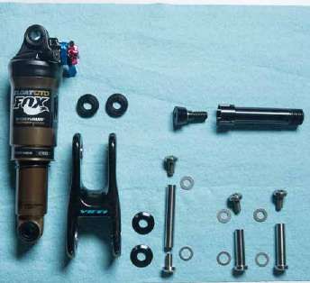
TABLE OF CONTENTS
     BRAND OVERVIEW         06

     FRAME FEATURES         08

     GEOMETRY               10

     MAINTENANCE SCHEDULE   12

     SETUP

     SHOCK SETUP            14

     QUICK START GUIDE      16

     CABLE/LINE SETUP       18

     TECHNICAL

     ASSEMBLY OVERVIEW      20

     EXPLODED VIEWS         28

     REBUILD KITS           31

     LEGAL

     WARRANTY               34

     CONTACT INFORMATION    35

4.                               5.
WELCOME TO THE TRIBE.
     CONGRATULATIONS ON YOUR
     PURCHASE OF A NEW YETI.
     We are confident your new bicycle will exceed                    This manual outlines basic setup and
     your expectations for value, performance, and                    maintenance recommendations of your new
     ride quality. Each frameset and component                        Yeti. Because it is impossible to anticipate
     has been custom specified and designed to                        every situation or condition that may occur
     enhance your riding experience. Whether you                      during the assembly, setup, and maintenance
     are a beginner cyclist, or a seasoned pro,                       of your bicycle, Yeti recommends that all
     your Yeti bicycle will provide endless hours of                  service and repairs be performed by your
     two-wheeled fun.                                                 local authorized Yeti Dealer.

     This model specific manual is designed to                        This manual contains many “Warnings” and
     be used in conjunction with the general Yeti                     “Cautions” concerning the consequences
     Owner’s Manual and the manuals supplied by                       of failure to maintain or inspect your bicycle.
     the suspension manufactures. If you did not                      The word “Warning” indicates a potentially
     receive the Yeti owner’s manual or the manual                    hazardous situation in which , if not avoided,
     provided by the suspension manufacturer                          could result in serious injury or death. The
     download the materials off the Internet, or                      word “Caution” indicates a potentially
     contact your local dealer.                                       hazardous situation in which, if not avoided
                                                                      may result in minor injuries or damage to
     Bicycling can be a hazardous activity                            your bicycle or a component of your bicycle.
     even under the best of circumstances.                            Be sure to read and understand all of the
     Proper maintenance of your bicycle is your                       Warnings and Cautions listed in the manual.
     responsibility and when done properly helps
     reduce the risk of injury and damage to your
     bicycle.

     Warning: Make sure you review and understand the warnings, instructions, and content of this manual and accompanying
     manuals for your bicycle.

     Warning: Technological advances have made bicycles and bicycle components more complex and the pace of innovation is
     increasing. It is impossible for this manual or the accompanying manuals to provide all the information required to properly
     repair and/or maintain your bicycle. In order to help minimize the chances of an injury, it is critical for you to have work
     performed by an authorized Yeti retailer.

6.                                                                                                                                  7.
OUR NEW ASR-C IS A                                                      1.    Yeti’s custom high modulus carbon construction offers unparalleled
                                                                                   stiffness and ride quality. It also offers best in category frame

     CROSS-COUNTRY RACE
                                                                                   weight.

                                                                             2.    Distinctive and functional Loopstays provide unparalleled ride

     MACHINE WITH AN
                                                                                   quality and stiffness.

                                                                             3.    Full carbon linkage reduces weight and increases stiffness. Plus it

     ENDURO ALTER-EGO.
                                                                                   looks pretty sweet too!

                                                                             4.    All pivots on the ASR-C are oversized and use custom Endure Max
                                                                                   bearings for smooth suspension and maximum wear life.

                                                                             5.    Our tapered inset head tube creates a stiff front end for superior
                                                                                   handling as well as a wide range of compatibility with forks and
     1.    HIGH MODULUS CARBON CONSTRUCTION                                        headsets.
     2.    SIGNATURE YETI “LOOPSTAYS”
                                                                             6.    With all of our bikes we make custom frame protectors, the ASR-C
     3.    CARBON LINK                                                             is no exception.

     4.    OVERSIZED PIVOT PINS WITH ENDURO MAX BEARINGS                     7.    Custom molded down tube protector keeps the frame looking
                                                                                   fresher longer and protects against the inevitable rock impacts.
     5.    TAPERED INSET HEADTUBE (44MM/56MM)

     6.    CUSTOM CHAIN-SLAP GUARDS                                          8.    This may be an “XC” bike, but it has the soul of an enduro machine.
                                                                                   We know you’ll be riding it with a dropper post.
     7.    CUSTOM DOWNTUBE GUARD

     8.    CABLE ROUTING FOR INTERNALLY ROUTED HEIGHT ADJUSTABLE SEAT POST   9.    The direct mount front derailleur allows for simple, light and precise
                                                                                   front shifting.
     9.    DIRECT MOUNT FRONT DERAILLEUR

     10.   INTERNAL SHIFTER AND BRAKE ROUTING                                10.   Internally routed shift cable routing keeps the cables clean and
                                                                                   keeps the bike’s lines clean too.
     11.   TWO WATER BOTTLE MOUNTS
                                                                             11.   The ASR-C is still an “XC” rig, so we included 2 water bottle
     12.   27.5” WHEELS ON XS, SM / 29” WHEELS ON MD, LG AND XL                    mounting locations.

                                                                             12.   We size the wheels to fit the rider, not the conventions. XS and SM
                                                                                   frames use 27.5 wheels to keep the rider on the bike, not in it.

8.                                                                                                                                                          9.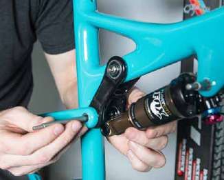
GEOMETRY
                                                                          FOX 32 / 120MM FORK
                                      B               M                             XS         SM            MD     LG     XL
                                                          I
                                                                           A        15.0       16.5          17.5   19.0   20.5

                                                                           B        21.7       22.7          23.7   25.7   25.7
                                          L
                                                                           C        68.0       68.0          69.1   69.1   69.1

                                                                           D        72.0       72.0          72.0   72.0   72.0

                                                                           E        17.3       17.3          17.5   17.5   17.5
                                                              J
                                A                                          F        42.2       43.3          44.5   45.5   46.5

                                                                           G        13.0       13.0          13.0   13.0   13.0

                                                                           H        28.7       28.7          28.7   28.8   28.9
                               D
                                                                           I        4.2        4.8           3.5    4.4    5.2
                                                                  C
                                                                           J        20.0       20.0          20.5   20.5   20.5
                                                                      K    K        1.73       1.73          1.73   1.73   1.73

                                                                           L        22.6       23.2          23.4   24.2   25.0
                     E                        G   H
                 F                                                         M        14.2       15.0          16.7   17.4   18.2

                                                                           WHL      27.5       27.5          29.0   29.0   29.0

                                                                           *All measurements are in inches

  FIT
      X-SMALL   4’11” (150 CM) - 5’3” (160 CM)

      SMALL     5'3" (160 CM) - 5'7" (170 CM)

      MEDIUM    5'7" (170 CM) - 5'11" (180 CM)

      LARGE     5'11" (180 CM) - 6'3" (191 CM)

      X-LARGE   6'3" (191 CM) - 6'6" (198 CM)

10.                                                                                                                               11.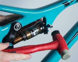
KEEP YOUR YETI FRESH
      AND CLEAN
      OVERVIEW                                                                                                                TORQUE
      Following these guidelines will help maintain the performance of your bicycle and prevent                               Yeti recommends using a torque wrench when assembling your frame. Torque specifications
      more serious problems from arising. It is important to remember that service intervals can vary                         for individual parts on the ASR-C are listed below, as well as in the step by step assembly
      depending on climate, trail conditions and riding frequency. If you are unsure about working on                         instructions later in the manual. For general bicycle maintenance please consult the torque
      your own bicycle, contact your authorized Yeti Dealer or visit the repair help section at www.                          specifications of the manufacture’s component you are adjusting.
      parktool.com for more information on general bicycle maintenance.

                                                                                                                              KEY TORQUE SPECS

                                                                                     WEEKLY

                                                                                              MONTHLY

                                                                                                        3 MONTHS

                                                                                                                   ANNUALLY
                                                                                                                              PART NUMBER                     DESCRIPTION                           TORQUE (NM)

                                                                                                                              300030150                       UPPER LINK PIVOT                      5NM
      SCHEDULE
                                                                                                                              300030154                       LOWER LINK PIVOT                      6.5NM
      CLEAN AND LUBE CHAIN
                                                                                                                              300030249                       FRONT SHOCK MOUNT                     6.5NM
      CHECK TIRE PRESSURE
                                                                                                                              300020047                       MAIN PIVOT AXLE                       9NM
      CLEAN BIKE OF MUD AND DEBRIS
                                                                                                                              300040454                       MAIN PIVOT COLLET                     13.5NM
      CHECK BRAKE FUNCTION

      CHECK SHOCK PRESSURE, IF APPLICABLE

      CHECK FOR LOOSE BOLTS AND TIGHTEN, IF NECESSARY

      CHECK HEADSET AND TIGHTEN / LOOSEN, IF NECESSARY

      THOROUGHLY CLEAN PIVOT POINTS WITH A RAG (DO NOT LUBRICATE)

      REPLACE BRAKE PADS, IF NECESSARY

      CHECK TIRES FOR WEAR

      CHECK SPOKE TENSION, RETENTION IF NECESSARY

      CHECK CHAIN FOR WEAR AND REPLACE IF NECESSARY

      COMPLETE TUNE-UP PERFORMED BY AN AUTHORIZED YETI DEALER

12.                                                                                                                                                                                                                         13.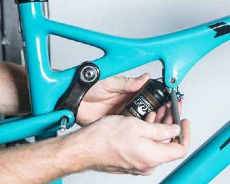
SHOCK SETUP
      YETI TIPS                                        TOOLS NEEDED
      Inspect your shock for any visible damage.       • Shock Pump
      If oil is leaking or you notice any damage to    • Tape Measure
      the surfaces or seals, please contact the Fox
      Racing Shox service center for repair at 800.
      FOX.SHOX.

      Shock set-up can fluctuate greatly based on                       01. AIR PRESSURE                                          02. SAG
      the rider. The set-up guide is intended as a                      The main air spring controls the sag of the shock.        Once you have set your baseline air pressure you
      base line to get the rider started. Experiment                    For the ASR-C to ride properly it is important to         need to measure the sag. To measure the sag
      with your settings to find the set-up that                        setup the shock with the correct amount of sag.           slide the travel indicator (O-Ring) up against the
                                                                        For general riding the ASR-C works best with 25-          shock body. With a friend supporting the bike,
      works best for you.                                               30% or 11mm of shock sag. To increase the sag             sit on the saddle (do not bounce) and allow your
                                                                        reduce the main spring air pressure. To reduce            body weight to compress the shock. Once you
                                                                        the sag increase the main spring air pressure.            have compressed the shock, get off the bike
                                                                                                                                  and measure the distance between the shock
                                                                                                                                  body and the new position of the travel indicator
                                                                                                                                  (O-Ring). This is your sag.

                                                                        03. REBOUND
                                                                        The rebound adjustment has 14 clicks of adjustment. The rebound knob is the red adjustment dial located
                                                                        above the blue compression damping adjustment lever. As a general rule, adjustments that are too fast
                                                                        (counter-clockwise adjustment) will produce a springy ride with excessive kick-up of the rear end causing
                                                                        a bucking sensation. Adjustments that are too slow (clockwise adjustment) will cause packing of the rear
                                                                        wheel indicated by a sluggish ride feeling ride.

                                                                        Slower rebound- turn the knob clockwise
                                                                        Faster rebound- turn the knob counter-clockwise
14.                                                                                                                                                                                    15.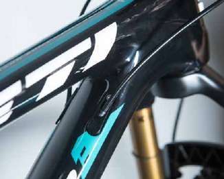
SHOCK SETUP

      04. COMPRESSION DAMPING                                        05. TRAIL ADJUST
      The compression damping has three levels of                    The trail adjust dial controls the “trail” mode low
      adjustment and is controlled by the blue lever                 speed compression adjustment. It has three
      on the shock. The “climb” mode engages the                     levels of adjustment and is controlled by the
      firmest low-speed compression setting for                      black dial on the shock body. Turning the dial
      maximum pedaling efficiency. The “trail” mode                  clockwise increases low speed compression
      engages a moderate low-speed compression                       damping, making the shock feel stiffer under low
      setting for an optimal blend of pedaling efficiency            speed compressions. Turning the dial counter-
      and bike control, on various riding terrain.                   clockwise will decrease low speed compression
      Finally, the “descend” mode sets the low-speed                 damping, making the shock feel softer under low
      compression setting to fully open, for maximum                 speed compressions. Please note this adjustment
      bike control and shock absorbency on steep,                    only affects the shock performance while riding in
      aggressive descents.                                           “trail” mode.

      QUICK START GUIDE - CTD ADJUST
      ADJUSTMENT                                    SETTING

      AIR SPRING SETTING (PSI)                      RIDER WEIGHT LESS 10 PSI

      MEASURED SAG (MM)                             11MM

      REBOUND                                       *5 CLICKS

      COMPRESSION DAMPING                           BASED ON TERRAIN

      TRAIL ADJUST                                  POSITION 2

      *All clicks are counted clockwise, rotating from the all the
      way out or counter - clockwise dial position.

16.                                                                                                                        17.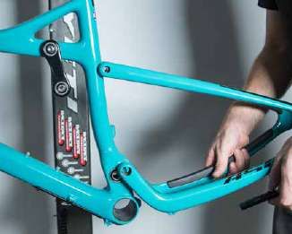
CABLE SETUP                                                                                                          03. REAR DERAILLEUR
      YETI TIPS                                                                                                            Measure the appropriate amount of shifter housing. There are going to be two segments; one from the
                                                                                                                           handlebar to the top housing stop port and one from the bottom housing stop port to the rear derailleur.
      The ASR-C uses internal routing for the derailleurs. By using internal routing we have eliminated                    From the shifter, run the housing parallel to the brake line around the head tube to the upper port on the
      exposure and cleaned up the look. This also reduces the entrance of unwanted elements such                           non drive side of the down tube. Thread the cable through the down tube to the lower port just above the
                                                                                                                           BB. Removing the lower housing stop port will make this easy. Thread the cable through the non drive
      as sweat and sediment into your shifting system. Use of internal cable routing will leave the
                                                                                                                           side of the housing stop and re install. Thread the cable through the 2nd housing segment and route the
      bike looking clean and keep your shifting smoother for a longer period of time.                                      housing along the underside of the drive side chain stay. Follow the housing guides to the derailleur, leaving
      Caution: The failure to properly route shifter housing can cause malfunction and unexpected shifting.
                                                                                                                           enough slack to allow for suspension movement. Adjust your derailleur according to the manufacturers
                                                                                                                           specifications. Note: You may want to route the front shift cable at the same time for easiest installation.

        01. INTERNALLY ROUTED DROPPER POST
        From the handle bar lever, your internally routed
        seat post line will parallel the rear brake line
        down the down tube. Curve the line around the
        bottom of the bottom bracket and up to the port
        on the back of the seat tube. The line should
        pass between the chain stay bridge and the front
        triangle. Each seat post is different, please follow
        the instructions from the manufacturer of your
        seat post for full installation procedure.

                                                                                                                           04. FRONT DERAILLEUR
                                                                                                                           Measure the appropriate amount of shifter housing. There are going to be two segments; one from the
                                                                                                                           handlebar to the top housing stop port and one from the bottom housing stop port to the front derailleur.
         02. REAR BRAKE                                                                                                    From the shifter, run the housing around the head tube to the upper housing stop port on the drive side of
         From the handlebar, the rear brake line is routed around the non drive side of the head tube. There are zip tie   the down tube. Thread the cable through the down tube to the lower port just above the BB. Removing the
         cable housing guides down the down tube from there to the bottom bracket. Loosely zip tie the housing to          lower housing stop port will make this easy. Thread the cable through the drive side of the housing stop and
         each guide to allow for adjustment. Follow the housing guides under the BB to the non drive side chain stay       re install. From the lower housing stop port there is a short segment of housing to the stop on the back of
         leaving enough slack to allow for suspension movement. The housing should be routed on the inside of the          the BB. Make sure there is a gentle curve in that segment to allow for smooth shifting. From there route the
         chain stay to the caliper. Once everything is in place tighten your zip ties all the way.                         bare cable to your front derailleur and set up according to manufacturer specifications.

18.                                                                                                                                                                                                                                         19.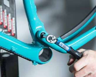
ASSEMBLY
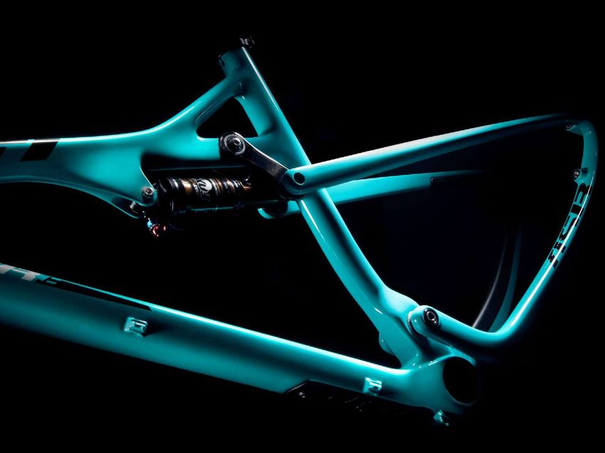
YETI TIPS TOOLS NEEDED
Make sure your tools are in good condition. • Dead blow hammer
A worn allen key can round the hex on a bolt • Two - 5mm allen keys
not allowing for proper torque. • 10mm allen key
• Guide pin tool
Torque settings are listed throughout the • Grease
instructions. It is import to properly prep all • Blue Loctite (248)
bolt threads. The instructions denote whether • Pink Loctite (222) 01. 02.
to use a Loctite compound or grease. Find and place the upper link spacers while While holding the upper link spacers slide the
holding the link. link in place. Have a Fox guide pin easy to reach
before you do this. Slide the guide pin through
the link, spacers and frame to hold everything in
Warning: Service on Yeti bicycles requires special knowledge place.
and tools. Yeti Cycles recommends that all service and
repairs be performed by an authorized Yeti Dealer
03. 04.
Using the Fox guide pin, insert the female upper Prep male bolt with blue (248) Loctite.
link pivot pin. Remove the guide pin and place in
an easy to reach place.
20. 21.ASSEMBLY ASSEMBLY
05. 06. 09. 10.
Loosely thread the male bolt into the upper link Finish tightening the upper link pivot using a well Slide the main pivot axle into the swingarm Thread the main pivot axle in using a 10mm allen
pivot pin on the frame. Do not overtighten. calibrated torque wrench set to 5 Nm through the non drive side. Using a Fox guide pin wrench and torque to 9 Nm.
to align the pivot sleeve slide the main pivot axle
through until it contacts the threads
Torque to 5 Nm Torque to 9 Nm
07. 08. 11. 12.
Prep the main pivot axle with grease. Slide the swing arm into place over the main pivot Prep the lower link shock spacers with a small Place the shock spacing washers against the
sleeve on the front triangle. amount of grease. This will help them stay in bearings on the inside of the link using the grease
place on the link. to hold them in place.
22. 23.ASSEMBLY ASSEMBLY
13. 14. 17. 18.
Use a Fox guide pin to align the link, spacers and Slip the front shock mount into the front triangle Using the guide pin slide the front shock Apply blue (248) Loctite to the male bolts for the
the swingarm. and use another Fox guide pin to align and hold mounting hardware through the frame and shock. shock mount and the lower link pivot at this time.
it in place. Use a soft mallet to tap it through if necessary.
15. 16. 19. 20.
pull the lower link guide pin back, leaving it Using the guide pin, slide the lower link pivot Using a well calibrated torque, wrench tighten the Using a well calibrated torque, wrench tighten the
partially in place. Give yourself clearance for the hardware through the swingarm, link and shock. lower link hardware to 6.5 Nm. front shock mounting hardware to 6.5 Nm.
rear of the shock to slide into place. Place the Use a soft mallet to tap it through if necessary.
shock into the link and reinsert the guide pin.
Torque to 6.5 Nm Torque to 6.5 Nm
24. 25.ASSEMBLY
21. 22.
Prep your collet bolt with grease. Thread the collet bolt into the main pivot axle.
Using a well calibrated torque wrench, torque to
13.5 Nm.
Torque to 13.5 Nm
23.
The completed ASR-Carbon frame. Now put
some parts on it and go for a ride!
26. 27.EXPLODED VIEW
30 2
25 1
29
21 20
21 18
19
9 8
GREASE LOCTITE
8
9
21
21 19
24
29
30
26
31 3
30
29
14 29 31 28
23 22
222
31
27
12
11
10
4 12
16 5 11 13
11
4
15 11 13
6 7
17
28. 29.EXPLODED VIEW PARTS LIST
ITEM# PART # DESCRIPTION QTY ITEM# PART # DESCRIPTION QTY
1 N/A ASR-C FRONT TRIANGLE 1 26 300030288 STUD YETI TI FEMALE 8.0OD X 54MM, M6 1
2 300070006 ICE AXE HEAD BADGE 1 27 300030150 BOLT YETI TI FEMALE 8.0OD X 36.5MM, M6 1
3 300060072 YETI SEAT CLAMP STANDARD 1 28 300030249 BOLT YETI TI FEMALE 8.0OD X 31.5MM, M6 1
4 300020045 BEARING F6902 2RS-MAX 28X15X7 2P5-OUT 2 29 300030151 BOLT TI MALE M6X12.0MM 4
5 300030272 SPACER 15MM X 23.75MM 1 30 300030062 WASHER 6.5X12.5X0.5 MM 3
6 300040442 PORT STOP, DOWN TUBE LOWER 1 31 300030069 WASHER 8.8X12.5X0.5 MM 3
7 300030244 BOLT BUTTON HEAD (M3X0.5X8) 1
8 300040441 PORT STOP, DOWN TUBE UPPER 2
9 300030215 BOLT FLAT HEAD (M3X0.5X8) 2
10
11
400100107
300030148
PROTECTOR ASR-C DOWN TUBE
WASHER 5.1X8.9X1MM
1
4 REBUILD KITS
12 300030010 BOLT-CAP H20 (M5 X 0.8 X 16MM) 2
PART # DESCRIPTION QTY
13 300030119 SCREW CAP (M5X0P8X10) 2
200020220 LINK ASR-C W/BEARING 1
14 N/A ASR-C REAR TRIANGLE 1
15 400100108 CHAIN STAY PROTECTOR ASR-C 29 1
200020225 ASR-C CABLE GUIDE KIT
400100117 CHAIN STAY PROTECTOR ASR-C 27.5 1
300030215 M3X.5X8 FLAT HEAD BOLT 1
16 400100109 SEAT STAY PROTECTOR ASR-C 29 1
300030244 M3X.5X8 BUTTON HEAD BOLT 2
400100118 SEAT STAY PROTECTOR ASR-C 27.5 1
300040441 PORT STOP DT UPPER 1
17 300060070 12X142 HANGER STD KIT 1
300040442 PORT STOP DT LOWER 2
18 N/A FOX FLOAT CTD 6.5X1.5 1
19 214-09-006 FOX MOUNT KIT 21.84MM (22MM) 2
20 200020203 ASR-C LINK 1
21 300020048 BEARING 608-SRS-MAX 22X8X7 1-IN 4
22 300040457 COLLET_AXLE_15X51.5SX12.0T_M15X1.5 1
23 300040454 COLLET-WEDGE ASSEMBLY 1
24 300020047 SHOCK SPACER 4.5MM 2
25 300040451 INNER RACE EXTENDER 2
30. 31.REBUILD KITS CONTINUED
PART # DESCRIPTION QTY PART # DESCRIPTION QTY
200020222 ASR-C MASTER REBUILD KIT 200020223 ASR-C HARDWARE KIT
300020045 BEARING F6902 2RS 28X15X7 OUT 2 300020047 SPACER 8MM X 4.5MM FOR SHOCK 2
300020047 SPACER 8MM X 4.5MM FOR SHOCK 2 300030062 WASHER SS 6.5MM ID 12.5 OD .5M 3
300020048 BEARING 608 FE 2RS 4 300030069 WASHER SS 8.8MM ID 12.5MM OD . 3
300030062 WASHER SS 6.5MM ID 12.5 OD .5M 3 300030150 BOLT-TI-FEMALE 8.0X36.5MM 1
300030069 WASHER SS 8.8MM ID 12.5MM OD 3 300030151 BOLT-TI-MALE M6X12MM 4
300030150 BOLT-TI-FEMALE 8.0X36.5MM 1 300030154 STUD-TI-FEMALE 8X54.5MM 1
300030151 BOLT-TI-MALE M6X12MM 4 300030215 M3X.5X8 FLAT HEAD BOLT 2
300030154 STUD-TI-FEMALE 8X54.5MM 1 300030244 M3X.5X8 BUTTON HEAD BOLT 1
300030215 M3X.5X8 FLAT HEAD BOLT 2 300030249 BOLT-TI-FEMALE 8.0OD M6X31.5M 1
300030244 M3X.5X8 BUTTON HEAD BOLT 1 300040441 PORT STOP DT UPPER 2
300030249 BOLT-TI-FEMALE 8.0OD M6X31.5M 1 300040442 PORT STOP DT LOWER 1
300030272 SPACER 15X23.75MM 1 300040451 INNER RACE EXTENDER ASR-4C 2
300040441 PORT STOP DT UPPER 2 300040454 COLLET-WEDGE ASSEMBLY GEN2 1
300040442 PORT STOP DT LOWER 1 300040457 AXLE COLLET 15X51.5SX12.0T 1
300040451 INNER RACE EXTENDER ASR-4C 2
300040454 COLLET-WEDGE ASSEMBLY GEN2 1 400100123 ASR-C PROTECTOR KIT 29ER
300040457 AXLE COLLET 15X51.5SX12.0T 1 400100107 PROTECTOR DOWN TUBE ASR-C 1
400100108 PROTECTOR SEAT STAY ASR-C 29 1
200020224 ASR-C BEARING REBUILD KIT 400100109 PROTECTOR CHAIN STAY ASR-C 29 1
300020045 BEARING F6902 2RS 28X15X7 OUT 2
300020048 BEARING 608 FE 2RS 4 400100123 ASR-C PROTECTOR KIT 27.5
300030272 SPACER 15X23.75MM 1 400100107 PROTECTOR DOWN TUBE ASR-C 1
400100117 PROTECTOR SEAT STAY ASR-C 27 1
400100118 PROTECTOR CHAIN STAY ASR-C 27 1
32. 33.WARRANTY
YETI LIMITED (5) FIVE YEAR FRAME WARRANTY in the form of cracks, fracture lines, deformation, dents, and any other visual indicators of
(applies to SB5c / SB6c / ASR-4 / 575 / ARC-C) abnormality. These safety checks for frame stress are important to prevent accidents, injury to
the cyclist, and product failure of a YETI frameset.
Yeti Cycles will repair or replace, at its option, any of the above listed frames it determines to
be defective due to defective materials and/or workmanship. The (5) five year limited warranty DISCLAIMER
is conditioned upon the bicycle being ridden under normal conditions and having been YETI Cycles is not responsible for any damages to you or others arising from riding,
properly maintained. This warranty does not apply to the components attached to the frameset transporting or other use of your bicycle. In the event that your frame breaks or malfunctions,
such as suspension components, wheels, drive train, brakes, seat post, handlebar and stem. YETI Cycles shall have no liability or obligation beyond the repair or replacement of your frame
This warranty applies only to the original owner and is non-transferable. This warranty is void if pursuant to the terms outlined in the warranty.
the bicycle was not properly assembled by an authorized Yeti dealer.
ADDITIONAL CONDITIONS *If you have a warranty concern, please contact your authorized Yeti dealer.
These limited warranties do not apply to normal wear and tear, nor to claimed defects,
malfunctions or failures that result from abuse, neglect, improper assembly, improper
maintenance, alteration, collision, crash or misuse. The original owner shall pay all labor
charges connected with the repair or removal of all components. Under no circumstance does
this limited warranty include the cost of travel or shipment to and from an authorized Yeti
dealer. In order to exercise your rights under these limited warranties, the bicycle or frameset
must be presented to an authorized Yeti dealer, together with proof of purchase.
*The above warranties have been in effect since January 2012. For warranty information on Yeti
frames sold prior to that date please consult your local authorized dealer.
NO FAULT REPLACEMENT POLICY YETI CYCLES
Yeti Cycles will make replacement parts available at a minimum charge to the original owner 621 Corporate Circle, Unit B
in the event of a crash or any other non-warranty situation. Yeti Cycles does this at its sole Golden, CO 80401
discretion and reserves the right to refuse this offer. (p) 303-278-6909
(f) 303-278-6906
PRODUCT LIFE CYCLE www.yeticycles.com
Every YETI frameset has a useful product life cycle. The length of that useful product life
cycle will vary depending on the construction and the materials of the frameset, maintenance BUSINESS HOURS
and care the frameset receives , and the amount and type of use the frameset is subjected to Monday-Friday
over its life. YETI recommends that an authorized YETI dealer should inspect the frame for 8AM-11:30AM, 1:00PM-5:30PM
stress annually. Frame stress could cause potential failure and the signs are usually apparent (Mountain Time)
34.You can also read