GL-CO-RFG361 1-Channel Gas Leak Alarm System
←
→
Page content transcription
If your browser does not render page correctly, please read the page content below
GL-CO-RFG361
Date of Issue: 01/11/2012
Issue Number: 5.6
Page 1 of 7
GL-CO-RFG361
1-Channel Gas Leak Alarm System
Features: Benefits:
Remote sensors for natural gas, LPG and Self-diagnosis fault system
CO Audio & visual alarms
1 x SPST relay outputs
DIN-rail as standard, panel mounting kit
available
Adjustable alarm thresholds
Technical Overview
The CL-CO-RFG361 is a single channel gas leak alarm system, that is designed for the detection of gas leaks in
spaces such as boiler plant rooms, workshops and other industrial gas installations, to provide safety alarm and
shutdown facilities on detection of gas leakage.
Tel: +44 (0)1732 861200. - E-mail: sales@sontay.com. - Web: www.sontay.com.
© 2012 Sontay Limited. All rights reservedGL-CO-RFG361
Date of Issue: 01/11/2012
Issue Number: 5.6
Page 2 of 7
Specification: Part Codes:
Power supply 230Vac ±10% @ 50/60Hz Controller
Power consumption 3VA GL-CO-RFG361
Radio disturbance VDE0875/0871 1 Channel gas leak alarm system (DIN rail mount)
Vibration test with 2g (DIN 40046)
Relay output SPDT, 250V @ 5(1) A Mounting option
Housing dimensions 115 x 53 x 70mm GL-CO-FMK3
(4.53 x 2.09 x 2.76”) Panel mounting kit
Housing materials:
Cover ABS Sensors
Base Nylon GL-CO-SRS150
Housing protection IP30 Natural gas sensor
Sensor dimensions 77 x 77 x 44
(3.03 x 3.03 x 1.73”) GL-CO-SRS250
Sensor material Nylon LPG, Propane sensor
Sensor protection IP44
Ambient: GL-CO-SRS350
Storage temp. -25 to + 60°C (-13 to 140°F) Carbon Monoxide sensor
Operating temp. 0 to 45°C (32 to 113°F)
RH Class F Din 40040
Country of origin Italy
The products referred to in this data sheet meet the
requirements of EU 2004/108/EC and 2006/95/EC
Tel: +44 (0)1732 861200. - E-mail: sales@sontay.com. - Web: www.sontay.com.
© 2012 Sontay Limited. All rights reservedGL-CO-RFG361
Date of Issue: 01/11/2012
Issue Number: 5.6
Page 3 of 7
Siting of Devices:
Detectors
These must be sited in a dry space which meets the relevant ambient requirements given on page 2.
If installed in a location classified as “Hazardous” it must be installed in a cabinet for electrical equipment constructed
according to the regulations in force for the class of danger concerned.
The controller can be mounted on a DIN rail and housed in a standard DIN enclosure.
Sensors
The correct siting of the sensor is fundamental for the correct functioning of the system. The position depends on the type of
gas to be monitored and, in particular, on its density in respect of air:
Methane (gas lighter than air which therefore tends to rise).
Position: at a distance of 10 to 50cm from the ceiling and, in any event, above doors or windows.
Propane (LPG) (gas heavier than air and so tends to move downwards).
Position: at a distance of 10 to 50cm from the floor.
Carbon monoxide (CO) (gas with a density very similar to that of air and which therefore tends to diffuse
uniformly)
Position: at a height of 150 to 200cm from floor.
Moreover, to ensure the correct operation of the detector and to avoid useless alarms due to a casual and momentary
presence of gas, the sensor must NOT be positioned:
Less than 1 to 2 metres from boilers or water heaters,
Less than 2 to 3 metres from kitchen ranges and ovens,
In spaces where air movement could be hindered (e.g. in corners or enclosed spaces),
Near to doors or windows,
Near to air extractors,
In places where dust or dirt could contaminate the sensor and so render it ineffective,
In places subject to possible sprays of water, particularly sensors positioned near the floor,
In places where the temperature or humidity could be outside the limits stated on page 2.
Solenoid shut-off valve
This must be installed on the gas distribution pipe, taking the following precautions::
If possible, in a different space from the one being controlled,
In an easily-accessible place, especially for the valves which have to be reset manually.
If installed outside, it must be protected against the weather,
In installations with external propane (LPG) gas tank, it must be installed downstream of the pressure-reducing valve
(30 to 40 mbar).
Tel: +44 (0)1732 861200. - E-mail: sales@sontay.com. - Web: www.sontay.com.
© 2012 Sontay Limited. All rights reservedGL-CO-RFG361
Date of Issue: 01/11/2012
Issue Number: 5.6
Page 4 of 7
Alarm Levels:
(In bold type threshold with Sensitivity = 0)
Methane Carbon monoxide (CO)
Alarm methane 0.5…0.8…1.25 % Warning: in detecting carbon monoxide (CO), the levels
5,000…8,000…12,500 ppm and intervention times are processed and controlled by
Pre-alarm methane 0.3...0.5...0.8 % a microprocessor. The “Sensitivity” control must be set
3,000...5,000...8,000 ppm in the “0” position.
Propane-GPL Carbon monoxide-CO alarm: "threshold + time"
Alarm propane-LPG 0.22…0.35…0.56 % < 50 ppm: no alarm
2,200…3,500…5,600 ppm 50...100 ppm: 60 minutes
Pre-alarm propane-LPG 0.14...0.22...0.35 % 100...300 ppm: 10 minutes
1,400...2,200...3,500 ppm >300 ppm: immediate alarm
Carbon monoxide-CO pre-alarm:
Time between exceeding alarm threshold and alarm
Installation:
1. The GL-CO-RFG361 should only be installed by a competent, suitably trained technician, experienced in installation
with hazardous voltages. (>50Vac & 75Vdc & 1500Vdc)
2. Ensure that all power is disconnected before carrying out any work on the GL-CO-RFG361.
3. Maximum cable is 2.5mm², care must be taken not to over tighten terminals.
4. Separate the base from the cover.
5. If DIN rail mounting clip onto the DIN rail.
6. Make connections as required using the following cables:
1.5 mm2 cross-section for power and relay control outputs,
1 mm2 cross-section for sensors positioned up to a maximum distance of 50 meters; or
1.5 mm2 cross-section for sensors positioned up to a maximum distance of 75 meters.
NB It is advised that no more than 2 cables be inserted into a single terminal. Use external junction boxes if
necessary.
7. Select the “link functions” to adapt the detector to the desired type of operational control.
Tel: +44 (0)1732 861200. - E-mail: sales@sontay.com. - Web: www.sontay.com.
© 2012 Sontay Limited. All rights reservedGL-CO-RFG361
Date of Issue: 01/11/2012
Issue Number: 5.6
Page 5 of 7
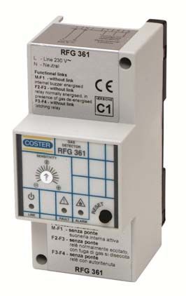
Fascia & Wiring:
Sensitivity adjustment Basic operation: Solenoid valve N/C:
Operational
control
Power LED Fault Alarm Reset button
Links:
Warning, when changing link functions ensure all power is disconnected first.
Link Functions:
M - F1 F3 - F4
No link Internal buzzer enabled No link Relay with latching alarm
Linked Internal buzzer disabled Linked Relay with non-latching alarm
F2 - F3
No link Relay normally energised when no gas present (1-3 closes 2-3 opens)
Linked Relay normally de-energised when no gas present (1-3 opens, 2-3 closes)
Latching alarm & reset:
F3 - F4 linked:
Alarm ceases when the gas concentration falls below the threshold level and the ALARM LED blinks slowly. Press the RESET
button to clear the LED status.
F3 - F4 unlinked:
Alarm continues even when the gas concentration falls below the threshold level. To deactivate press the RESET button for at
least 5 seconds.
Tel: +44 (0)1732 861200. - E-mail: sales@sontay.com. - Web: www.sontay.com.
© 2012 Sontay Limited. All rights reservedGL-CO-RFG361
Date of Issue: 01/11/2012
Issue Number: 5.6
Page 6 of 7
Operation:
Switching on
When it is powered the GL-CO-RFG361 does not start detecting immediately and does not signal any alarm for the first two
minutes of operation.
This is the time necessary for the gas-sensing elements to become stabilised so that their readout can be considered accurate
and reliable. This period for the stabilisation of the sensors is indicated, on the facia of the detector by the flashing of the
FAULT and ALARM LEDs. At the end of the stabilisation period the FAULT and ALARM LEDs, in normal situations, switch off.
Type of Fault Fault LED Alarm LED
Sensor self-heating element broken ON OFF
No connection to terminal G ON OFF
No connection to terminal B ON OFF
No connection to terminal M OFF ON
Connections G & B reversed ON OFF
Connections G & M reversed OFF ON
Connections B & M reversed OFF ON
Pre-alarm and alarm thresholds for methane and propane-LPG)
By means of the SENSITIVITY knob, the intervention threshold (sensitivity) can be increased or decreased according to the
particular conditions of the space in which the sensor is positioned, or for specific requirements:
Knob towards + = increase of sensitivity.
Knob towards - = decrease of sensitivity.
These adjustments, however, remain within the limits required by the regulations so it is always possible to intervene under
conditions of the maximum safety.
The intervention levels, referred to the LEL (Lower limit of Explosivity) = volumetric ratio in air of combustible gas or vapour
below which an explosive mixture is not formed) for the gases methane and propane LPG are as follows (the threshold values
with the “SENSITIVITY” knob = 0 are shown in bold type):
Type of gas LIE Pre-Alarm Alarm threshold
Methane 5% 0.2..0.5..0.8% 0.5..0.8..1.25%
50000ppm 3000..5000..8000ppm 5000..8000..12500ppm
Propane (LPG) 2.10% 0.14..0.22..0.35% 0.22..0.35..1.25%
21000ppm 1400..2200..3500ppm 2200..3500..5600ppm
Pre-alarm and alarm threshold for carbon monoxide (CO)
The danger of carbon monoxide (CO) does not derive from its inflammability or the danger of explosion, but from its very
high toxicity to the human body. Moreover, its danger does not depend only on the concentration of the gas in air, but also
on the length of time a person has remained in an atmosphere in which this gas is present.
The pre-alarm and alarm levels of the sensor are determined by the processing of a microprocessor which takes
into account the concentration of the gas in the air and the exposure time. For this reason the “Sensitivity” knob
on the detector must not influence the sensor readout and, even if there is only one carbon monoxide (CO)
sensor, it must be set in “0” position.
Tel: +44 (0)1732 861200. - E-mail: sales@sontay.com. - Web: www.sontay.com.
© 2012 Sontay Limited. All rights reservedGL-CO-RFG361
Date of Issue: 01/11/2012
Issue Number: 5.6
Page 7 of 7
Operation (continued):
The intervention modes of the detector are accordingly as follows:
Concentration < 0.005% (50 ppm): the safety of the persons is guaranteed for an indefinite length of time and so
the detector does not intervene,
Concentration 0.005...0.01% (50...100 ppm): within this concentration range, for 60 minutes the detector signals
a “Pre-alarm” situation and after this period switches to “Alarm”.
Concentration 0.01...0.03% (100...300 ppm): within this concentration range, for 10 minutes the detector signals
a “Pre-alarm” situation and after this period switches to “Alarm”.
Concentration > 0.03% (300 ppm): the safety of the persons present in the space is not guaranteed.
The detector immediately switches to the “Alarm” state. The concentration values and times taken into
consideration by the detector have been established allowing a large safety margin to ensure there is no danger to
the persons.
The action of the detector is of the “Dynamic” type: if the concentration passes from one level to another, the time
calculated increases or decreases as a consequence, thereby modifying the response of the detector. In particular, should the
concentration of carbon monoxide (CO) return below 0.005% (50 ppm) for more than one minute, the detector returns to
the “Normal” condition, cancelling all the times counted up to that moment and, if it has been programmed “Without
latching” any “Alarm” condition will be terminated.
Commissioning:
Power the device: LINE LED lights and FAULT LED and ALARM LED flash.
After 1.5…2 minutes the detector is enabled to acquire alarms and the LEDs FAULT and ALARM should go out.
Position the SENSITIVITY knob on "0".
Since the sensors are selective, and so not influenced by gases other than that for which they are dedicated, to
simulate the presence of gas it is necessary to use small gas cylinders containing specific gases at preset
concentrations, releasing the gas as near as possible to the detecting sensor. Only for sensors for detecting propane
(LPG) can gas from a normal cigarette lighter be used.
When the gas concentration exceeds the pre-alarm threshold the ALARM LED flashes.
With a delay (about 20 seconds) after exceeding the alarm threshold:
ALARM LED lights and stays lit.
The internal alarm and the outside warnings (only if without jumper M-F1) are switched on.
The operational relay closes the gas shut-off valve or switches on the aeration fan.
Stop erogation of gas. When gas concentration on the sensor returns below the threshold level:
If detector is “without latching” (with jumper between F3-F4), alarm ceases and ALARM LED remains
flashing slowly until RESET button is pushed
If detector is “with latching” (without jumper between F3-F4), alarm remains until RESET button is pressed
for at least 5 seconds.
If the detector controls a valve with manual reset, it is necessary to re-open manually also the valve.
Whilst every effort has been made to ensure the accuracy of this specification, Sontay cannot accept responsibility for damage, injury,
loss or expense from errors or omissions. In the interest of technical improvement, this specification may be altered without notice.
Tel: +44 (0)1732 861200. - E-mail: sales@sontay.com. - Web: www.sontay.com.
© 2012 Sontay Limited. All rights reservedYou can also read