Experimentation on Exhaust System Using TWC Converter For Diesel Engine Emissions
←
→
Page content transcription
If your browser does not render page correctly, please read the page content below
International Journal of Engineering Science Invention
ISSN (Online): 2319 – 6734, ISSN (Print): 2319 – 6726
www.ijesi.org Volume 2 Issue 9ǁ September 2013 ǁ PP.45-53
Experimentation on Exhaust System Using TWC Converter For
Diesel Engine Emissions
D S Jaheer Basha M.Tech1, M A Chakravarthy M.Tech2 ,
N Haranadh M.Tech.3
1,2,3
(Assistant Professor of Mechanical Engineering Department, sri venkateswara college of engineering &
technology (autonomous), chittoor, Andhra Pradesh, India--517127)
ABSTRACT : We prepared a new kind of exhaust after-treatment system having Diesel Particulate Filter,
Three Way Catalytic (TWC) converter (in substitution of SCR & Oxidation catalyst) to determine the scope for
enhancing the efficiency of a Three Way Catalytic (TWC) converter system. Our results show that there is a
~99% reduction in the CO and HC emissions after arranging the retrofit. We also found that on an average
there is a 72% reduction in the NOx.
KEYWORDS : Diesel engine, DPF, Emissions, SCR, TWC.
I. INTRODUCTION
The introduction of exhaust gas after treatment systems for diesel engines is a measure to fulfill the
legislation requirements [1],[2]. Selective catalytic reduction (SCR) are considered to be promising for this
better performance[3]. Therefore, in Europe, on road demonstrations of the SCR systems are conducted[4].
However, there are problems yet to be solved for practical usage of SCR systems. The first one is the low
activation for NOx reduction under low exhaust gas temperatures and transient conditions encountered in real
operating conditions.The selective catalytic reduction (SCR) process is a well-established concept, but yet
commercially not proved technology for nitrogen oxide [NO x] emission control for automobiles. In particular,
ammonia [NH3]SCR featured by a reductant [NH3] added to the exhaust gas is recognized as a flexible remedy
for mobile diesel NOx emission[5],[6]. One of the major challenges in the automobile application of the NH 3
SCR process is the enhancement of the de-NOx performance at low exhaust gas temperatures below 300ºC. One
of the feasible methods to promote de-NOx activity at low temperatures is to lead the reaction to pass through
the fast SCR path.The present investigation concern with experiment on Diesel engine test-rig inorder to
determine the exhaust gas emissions at the end of tail pipe at different loads by arranging the setup proposed.
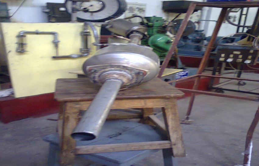
1.1.Diesel Particulate Filter
The catalyst commonly contains an alumina wash coat supported on a honeycomb shape ceramic brick
as shown in below Fig. 1.[7],[8],[9].
Figure 1: DPF
www.ijesi.org 45 | Page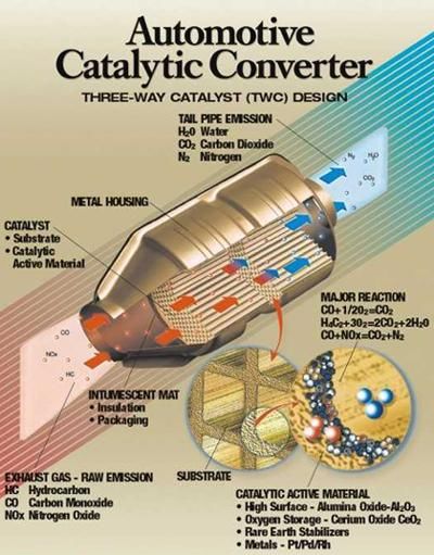
Experimentation On Exhaust System Using…
1.2. Three Way Catalytic (TWC) Converter
This catalyst takes its name from controlling the three major emissions in an engine that are NO X,
VOCs and carbon monoxide[10]. The catalyst commonly contains an alumina wash coat supported on a
honeycomb shape ceramic brick as shown in Fig. 2. Precious metals are coated onto the alumina[11]. The active
part of the catalyst is further divided into oxidation and the reduction catalyst sites[12].
Figure 2: Automotive Catalytic Converter (TWC)
The platinum/rhodium components act as the active sites to carry out reduction reactions, while
platinum/palladium acts as the active component for oxidation reactions[13],[14].
A: Reduction Catalyst
B: Oxidation Catalyst
C: Honeycomb Ceramic Structure
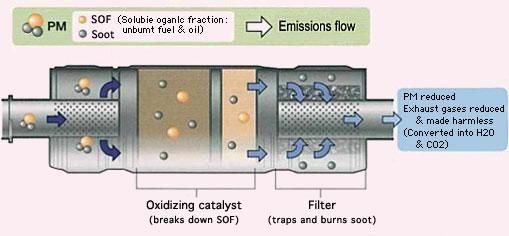
Reduction of nitrogen oxides to nitrogen and oxygen:
2NOx → xO2 + N2
Oxidation of carbon monoxide to carbon dioxide:
Figure 3: Section of TWC
2CO + O2 → 2CO2
Oxidation of unburnt hydrocarbons (HC) to carbon dioxide and water: CxH2x+2 + [(3x+1)/2]O2 → xCO2 +
(x+1)H2O.
II. EXPERIMENTAL DETAILS
2.1. Experimental Systems and Description
The experimental set up consists of single cylinder 4-stroke DI Diesel engine with 80mm bore-
diameter, 110mm stroke length, rated speed of 1500rpm, 5 BHP/3.7 KW rated power and water cooled engine.
2.2. Various parts of experimental setup {Refer : Fig.4}
1. kirloskar engine
2. alternator/dynamometer
3. alternative fuel tank
4. air filter
5. three-way valve
6. exhaust pipe
www.ijesi.org 46 | Page
Experimentation On Exhaust System Using…

7.    DPF
8.    multigas analyzer
9.    diesel tank
10    burrette
11.   three way valve
12.   control panel
13.   TWC (SCR+DOC)

                                                   13

               Figure 4: Line Diagram of Experimental Setup with Test-rig

                 DPF

                                                                            TWC

                     Figure 5:DPF+TWC Converter Experimental Setup with Engine

                                       www.ijesi.org                                     47 | Page
Experimentation On Exhaust System Using…
Figure 6: Auto Exhaust Multigas Analyzer Figure 7: DPF and TWC Converters
2.3 Experimental Procedure
As first said, pure diesel is allowed to run the engine for about 30 min, so that it gets warmed up and
steady running conditions are attained. Before starting the engine, the lubricating oil level in the engine is
checked and it is also ensured that all moving and rotating parts are lubricated.The various steps involved in the
setting of the experiments are explained below,
The tests were carried out after installation of the engine testrig with setup
Precautions are taken, before starting the experiment on selected engine.
The engine is started at no load condition.
After that engine is allowed to run at rated speed of 1500rpm atleast 10 minutes for stabilization.
The multigas analyser is prepared to take the required readings of engine emissions.
Then at 0 KW the probe of the multigas analyser is placed at the exhaust tail pipe and readings are
noted.
The above experimental procedure is repeated for different loads from no load to 2 KW load, for the
[1] same Engine at rated speed of 1500rpm in Two modes as follows:
[2] With-out connecting Diesel Exhaust Aftertreatment system at the end of exhaust tail pipe.
[3] With catalytic converters (DPF + TWC) connected at the end of exhaust tail pipe.
[4] After completion of the test, the load on the engine is completely relieved and then the engine is stopped.
III. RESULTS AND DISCUSSIONS
Experiments were conducted when the engine was fuelled with pure diesel. The experiment covered a
range of loads. The emission characteristics of the engine were observed in terms of concentration of CO, HC,
O2, NOx and CO2. The results obtained for with DPF+TWC converter +DEF system connected at the end of
exhaust tail pipe were compared with DPF+TWC converter connected at the end of exhaust tail pipe and
without connecting catalytic converter at the end of exhaust tail pipe.
www.ijesi.org 48 | Page
Experimentation On Exhaust System Using…

    Table I: Emission test Results for Pure Diesel (Without connecting catalytic converters at the end
                                       of exhaust tail pipe)

                               Load   Speed   CO      HC      CO2    NOX    O2
                       S.N0
                               kW      rpm    (%)     ppm     (%)    ppm    (%)

                         1      0     1500    0.074    52     1.1     44   19.08

                         2     0.5    1500    0.09     56     2.09   173   17.43

                         3     1.0    1500    0.084    81     3.5    532   15.32

                         4     1.5    1500    0.102   126     5.1    830   13.15

                         5     2.0    1500    0.155   239     8.2    942    9.05

Table II: Emission test Results for Pure Diesel (With DPF+TWC converter connected at the end of
                                         exhaust tail pipe)

                               Load   Speed   CO      HC     CO2     NOX    O2
                        S.N0
                                kW     rpm    (%)     ppm    (%)     ppm   (%)

                         1       0     1500    0       0      0.7    10    19.78

                         2      0.5    1500    0       0      1.4    60    18.65

                         3      1.0    1500    0       0      2.2    88    17.54

                         4      1.5    1500    0       0      2.6    231   16.7

                         5      2.0    1500    0       0      3.7    69    15.09

                 As per the above results tabulated the following graphs are drawn.

                                      Figure 8:Load against CO

                                      www.ijesi.org                                         49 | Page
Experimentation On Exhaust System Using…

   Figure 9: Load against HC

   Figure 10: Load against O2

www.ijesi.org                                   50 | Page
Experimentation On Exhaust System Using…

                                         Figure 11:Load against NOX

                                         Figure 12: Load against CO2
    As per the above results obtained the exhaust after treatment system with DPF+TWC converter is the best
                suitable for selected diesel engine to meet the diesel engine emissions legislation.

                                        IV.     CONCLUSIONS
Based on the values obtained for the tests conducted, the following conclusions are made
*    CO emission is zero for DPF+TWC converter system connected at the end of exhaust tail pipe when
     compared without connecting catalytic converter at the end of exhaust tail pipe. The CO emission is lower

                                          www.ijesi.org                                             51 | Page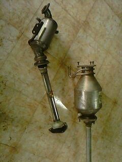
Experimentation On Exhaust System Using…

   when compared to the Bharat stage IV Norms for selected engine at all operated loads with retrofit
   arranged.
* HC emission is zero for DPF+TWC converter system connected at the end of exhaust tail pipe when
   compared without connecting catalytic converter at the end of exhaust tail pipe. The HC emission is lower
   when compared to the Bharat stage IV Norms for selected engine at all operated loads with retrofit
   arranged.
* Carbon dioxide emission is less for DPF+TWC converter system connected at the end of exhaust tail pipe
   when compared without connecting catalytic converter at the end of exhaust tail pipe.
* Oxygen concentration is more for DPF+TWC converter system when compared to without catalytic
   converter system at the end of exhaust tail pipe.
* Nitrogen oxides / dioxides (NOx) emission is less for DPF+TWC converter system when compared without
   connecting catalytic converter at the end of exhaust tail pipe. The NOx emission is lower when compared to
   the Bharat stage IV Norms for selected engine at all operated loads with retrofit.
*   From the above analysis the main conclusion is DPF+TWC converter system is suitable substitute for
   diesel engine exhaust after-treatment setup as this system produces lesser emission than existing at all loads.
Abbreviations
DI      Direct Injection
DOC     Diesel Oxidation Catalyst
DPF     Diesel Particulate Filter
SCR     Selective Catalytic Reduction
TWC Three Way Catalyst

                                            V.       ACKNOWLEDGEMENTS
          All praise to Almighty God (Allah) who is the only source of knowledge and without whose mercy
coming this far would only have remained a dream.
          Our special thanks to Professor A.RAMESH (I.C.Engines Lab Incharge), IIT-Madras for his kindness
and encouragement through our study period. Worth mentioning is the help, cooperation and encouragement
received from all our friends and co-researchers especially in the Reaction Eng & Catalysis Research group. We
Thank Assistant Professor A. VEERESH BABU, NIT-Warangal for some great and informative conversations
we had over the past few months. We would like to thank Department of Chemical Engineering & Mechanical
Engineering for the opportunity and the necessary facilities to carry out this research. We would like to highlight
our gratitude to Professor V.PANDU RANGADU for his constructive feedback and for the hours he put in
reviewing this work.
                                                        REFERENCES
[1]    “www.bosch-diesel.de” Robert Bosch GmbH 2011.
[2]    “www.wikipedia.org” Wikipedia®- trademark of the Wikimedia Foundation Inc- “Jan-2007”.
[3]    “www.epa.gov” U.S Environmental protection agency, website- “Jan-2007”.
[4]     “www.ec.gc.ca” The Green LaneTM, Environment Canada's World Wide Web site- “Jan- 2007”.
[5]    Heywood, J.B., “Internal Combustion Engine Fundamentals”, McGraw-Hill Book Co., Singapore, 1988.
[6]    Diesel Net website “www.dieselnet.com” copy right © 1997 - 2007 Ecopoint Inc “Jan-2007”.
[7]    Gallant, T.R. “Experimental Diesel Particulate Filter Capabilities at PNNL.” Diesel Exhaust Emissions Reduction Conference,
       Detroit, MI, August 24, 2006.
[8]    Blackman PG. Emission Control Options to Achieve Euro IV and Euro V on Heavy Duty Diesel Engines. SAE Journal. 2008;
       2008280021.
[9]    Saenz, N., H. Dillon, S. Carlson, and G. Maupin. “Advanced Metallographic Techniques Applied to Diesel Particulate Filters.”
       Microscopy Today, 2007: 15(5): p. 44.
[10]   Abdulhamid et. al, Influence of the type of reducing agent (H2, CO, C3H6 and C3H8) on the reduction of stored NOX in a
       Pt/BaO/Al2O3 model catalyst. (2004) Topics Catal. 30/31, p. 161.
[11]   Akira Obuchi et. al, Performance of platinum-group metal catalysts for the selective reduction of nitrogen oxides by hydrocarbons.
       Applied Catalysis B: Environmental Vol.2, Issue 1, 15 March 1993, Pages 71-80.
[12]   Andrea Scotti et. al, Kinetic study of lean NOX storage over the Pt- Ba/ Al2O3 system. Ind. Eng. Chem. Res 2004, 43, 4522-4534.
[13]   Burch et. al, A review of the selective reduction of NOX with hydrocarbons under lean-burn conditions with non-zeolitic oxide and
       platinum group metal catalysts. Applied Catalysis B: Environmental Volume 39, Issue 4, 20 December 2002, Pages 283-303.
[14]   Daniel Chatterjee, Olaf Deutschmann and Jurgen Warnatz(2001), Detailed surface reaction mechanism in a three way catalytic
       converter, Interdisciplinary Centre of Scientific Computing (IWR), Heidelberg University, 2001.

                                                   www.ijesi.org                                                            52 | Page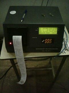
Experimentation On Exhaust System Using…

D. S. Jaheer Basha M.Tech                M A Chakravarthy M.Tech                 N Haranadh M.Tech
Advanced Internal Combustion Engines,    Advanced Internal Combustion Engines,   Advanced Internal Combustion
Engines,
P.G., Research Scholar,                  P.G., Research Scholar,                 P.G., Research Scholar,
Mechanical Engineering Department,       Mechanical Engineering Department,      Mechanical           Engineering
Department,
SVCET, Chittoor,                         SVCET, Chittoor,                        SVCET, Chittoor,
Andhra Pradesh,                          Andhra Pradesh,                         Andhra Pradesh,
India-517127.                            India-517127.                           India-517127.

                                        www.ijesi.org                                                53 | Page
You can also read