A coherent approach to managing geometry, idealisation and meshing for simulation
←
→
Page content transcription
If your browser does not render page correctly, please read the page content below

A coherent approach to managing geometry,
 idealisation and meshing for simulation

Emeritus Professor Cecil G Armstrong
School of Mechanical and Aerospace Engineering
Queen’s University, Belfast, N Ireland
Email: c.armstrong@qub.ac.uk
Publications: https://bit.ly/2MAsAdP
Presentation to Siemens Lecture Series on Geometry and Mesh Generation
25th February 2021

Acknowledgements

• Djinn
 • Cecil Armstrong, Adrian Bowyer, Stephen Cameron, Jonathan
 Corney, Graham Jared, Ralph Martin, Alan Middleditch,
 Malcolm Sabin, Jonathan Salmon https://bit.ly/3txpfgd
• QUB Academic:
 • https://www.qub.ac.uk/contact/Staff-directory/
 • Academic
 • Trevor Robinson, Declan Nolan
 • Recent Post Doctoral:
 • Chris Tierney, Flavien Boussuge flavien.boussuge@cea.fr, Liang
 Sun l.sun@ulster.ac.uk
• Recent PhD:
 • Benoit Lecallard, Dimitrios Papadimitrakis, Sriharsha
 Sheshanarayana, Andrew Colligan, Adam Clugston
• Siemens ex-QUB
 • Jonny Makem, Harry Fogg

Defining Simulation intent

Goal
• Capturing high level modelling & idealisation decisions in order to create a fit-for-
 purpose analysis model

 Equivalent
 geometries
 and
 meshes
Simulation Intent

• Need
 • Move from separate structural and fluid models (structures, gas paths, external
 and internal air flows etc.)
 • To a subdivision of space into cells of simulation significance, some of which are
 structural, some which are fluid etc.

• Maintaining a consistent, coherent description of the equivalent representations of a
 given region of space
 • Requires techniques for identifying the correspondence between different
 representations (geometry, mesh, surrogates, parameter sets, …)
 • Using geometric reasoning and relational learning to derive the equivalent
 representations
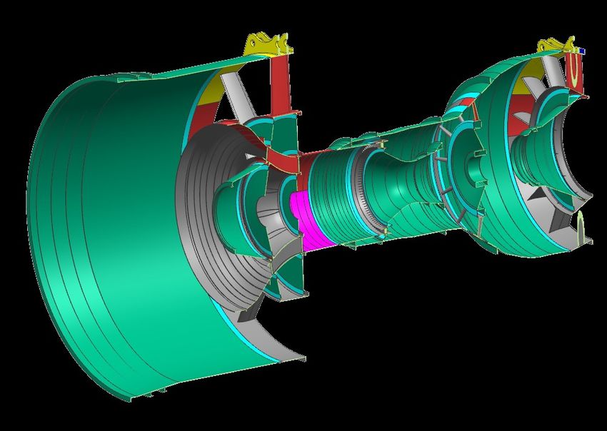
1. Cellular modelling

 Design volume divided into a non-manifold assembly of cells with simulation
 significance

 Multi-disciplinary Thin-sheet / long-
 slender
 Design geometry decomposition

 Structural and fluid cells

 Symmetry-based decomposition

CRESCENDO Engine used with permission from Rolls-Royce
2. Virtual topology
• No change in the underlying geometry
 • Abstract analysis topology: hints to mesh generator for vertices and edges to
 ignore
• Avoids time-consuming geometric operations
 • Use partitioning and de-partitioning to identify analysis topology on the same
 geometry
 Detailed design Abstract
 geometry analysis Mesh
 topology

 Heal sliver face
Partitioning

• Hard geometry e.g. to define Boundary Condition
• Soft geometry e.g. to define partitions for structured meshing

 Partition
Partitioning for hex meshing

 Investigating singularities in hex meshing, Dimitrios Papadimitrakis et al., submitted for publication
3. Equivalencing
• Specifying how different models represent the same region of space
 • Alternative geometric and analysis representations of the same cells or groups of
 cells
 • Equivalent models for different physics and fidelity

 Equivalent
 geometric and
 analysis models

 CRESCENDO Engine used with permission from Rolls-Royce
Lanyon building, Queen’s University Belfast

Applications of Simulation Intent
Robust boundary condition application
 Boundary conditions applied Boundary conditions do not
 to specific faces in the model propagate to new faces
 Design update
 causes topology
 changes

 Current approach

 Cellular modelling approach

 Solid-fluid interface

 Interface = FLUIDA ∩ ENGINE
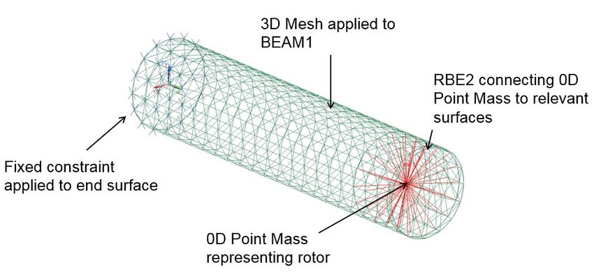
Re-use Simulation Intent
 Interfaces calculated
 Note: we can start with an abstract representation and
 add detail as the design evolves

 1D beam + 0D mass Simulation Intent:
 • A fixed constraint
 at the interface of
 Cantilever example
 BEAM1 and ROW1
 • BLOCK1 reduced
 Interfaces calculated
 to 0D point mass
 • BEAM1 3D tet
 meshed

 Different model same
 Simulation Intent
Lanyon building, Queen’s University Belfast

Equivalent representations: decomposition into
 thin sheet / long slender / complex 3D regions
Geometric reasoning: Medial Axis Transform

• Locus of centre of inscribed ball of maximal
 diameter
• Provides:
 – Lower dimensional skeleton
 – Proximity and local thickness
 – Aspect ratios
– Applications in
 – Dimensional reduction
 – Mesh generation
 – Detail finding and suppression
Multiple linked analysis models

 Tet
 elements
 Complex
 region
 Long,
 (yellow) Hex
 slender
 region (blue) elements

 2D shell
 elements
 1D beam
 elements
 Thin region
 (green)

 3D Tet elements (or 0D
 mass and inertia + links)
CRESCENDO Engine used with permission from Rolls-Royce
 J.E. Makem, C.G. Armstrong, T.T. Robinson, Automatic decomposition and efficient semi-structured meshing of complex solids, Eng. Comput. 30 (2012) 345–361.
 D.C. Nolan, C.M. Tierney, C.G. Armstrong, T.T. Robinson, Defining Simulation Intent, Comput. Des. 59 (2015) 50–63.
The problem with dimensionally-reduced models

• At joints, the solution to the FE problem is of full dimension
 • ∴ Mixed-dimensional models, coupled using MPCs
 • Error estimates from implied stress jumps (adaptive model refinement)
 • Abstracted as equivalent joint stiffness
 Rel Energy Error based on Stress Ju
 Stepped end loaded mixed dimensl mod
 0.0015

 Relative energy error
 0.001

 0.0005

 0
 0.25 0.5 0.75 1 1.25
 Distance per unit width to end of step

 Error energy/Total energy ratio

 R. W. McCune, C. G. Armstrong, and D. J. Robinson, “Mixed-dimensional coupling in finite element models,” Int. J. Numer. Methods Eng., vol. 49, no. 6, pp. 725–750, 2000.
 R. J. Donaghy, C. G. Armstrong, and M. A. Price, “Dimensional Reduction of Surface Models for Analysis,” Eng. Comput., vol. 16, no. 1, pp. 24–35, 2000.
Thick-thin decomposition

• Original bodies - 6503

• Thin-sheet = 7278 bodies (~65
% of volume)
• Thick = 6032 bodies
• (~33 % of volume)

• Number of unprocessed bodies
= 3595
• (~2% of volume)
• (55% of number of bodies)

 VESTA Engine used with permission from Rolls-Royce
 VESTA Engine used with permission from Rolls-Royce
Lanyon building, Queen’s University Belfast

Equivalent representations: exploiting axial
 symmetry
Quasi-axisymmetric models – dimensional reduction
• Gas turbine engines that have a lot of
 symmetry about the rotational axis!
• Starting from facetted model project all facets
 of 3D model to r-z plane
 • Identify facets
 • With zero area (F1-F5)
 • With non-zero area (F6-F9)
 • Silhouette edges
 • Adjacent facets change
 area sign
 • Build axisymmetric profile
 • Correct material properties
Quasi-axisymmetric models

• Automatically reduce to an axisymmetric model
• Calculate shape properties
 • Update material properties accordingly

 3D VS 2D-axisymmetric at
 sample points
 550

 3D temperatures (C)
 11 8 9
 14
 7 10
 450 5 12
 13 6
 350 3 1
 4 15
 2
 250
 250 350 450 550
 2D temperatures (C)
Features of interest for quasi-axisymmetric models

• Axisymmetric
 • For analytical surfaces, easy to identify those with symmetry about a given axis: cylinders,
 cones, spheres, tori, planes perpendicular to the axis etc
• Cyclic features
 • If there a rotational transform to bring a given geometry to = 0? Are there similar features
 at multiples of ?

 Face classification Virtual decomposition

 Cyclic grouping
Minimal meshable representation
• Using geometric reasoning to
 partition a model up into
 regions for which meshing
 strategies are known

• Minimal meshable
 representation is the minimum CRESCENDO assembly
 number of cells we need to Symmetry based
 mesh, to mesh the entire decomposition
 assembly

• Each different region type can
 be meshed using different
 strategies 60% - axisymmetric
 28% - cyclic
 5% - transition
• Transition cells can be used to 2% - sweepable
 create meshes to join different 1% - block topology Minimal meshable
 meshes together 4% - residual representation

 CRESCENDO Engine used with permission from Rolls-Royce 10.14733/cadaps.2019.478-495
Non-planar cuts for cyclic repeats

 1- Delaunay Triangulation of 2- Approximate medial edge from
 opposite edge features triangulation

 3- Generate cut surfaces and
 partition

 Benoit Lecallard (for Jonny Makem)
28th IMR, Buffalo, NY, USA
 Marie Curie Individual
 Fellowship: MUMPS

 APPLICATION OF TENSOR FACTORISATION
 Next Generation
TO ANALYSE SIMILARITIES IN CAD ASSEMBLY Digital Mock-Ups
 MODELS* for Multi-Physics
 Simulation
 Flavien Boussuge, Christopher M. Tierney,
 Trevor T. Robinson, Cecil G. Armstrong https://www.qub.ac.uk/research-
 centres/FiniteElementModellingGroup/Projects/
 mumps/

 *Best paper award, submitted to CAD
Statistical Relational Learning

All relationships between entities
are stored in one large tensor
• 0 : “is bounded by”, e.g. face 1 is
 bounded by edge 24
• 1 : “is type”, e.g. face 1 is planar
• 2 : “is interfacing with”, e.g. solid
 1 is interfacing with solid 5
• 3 : interface “is type” (contact, can be factorized as
 interference, gap) e.g. solid 1 is in ≈ , ∈ 1. .
 contact with solid 5 The returned matrix contained the “latent variables”
 for all entities
 Adjacency matrix is the same for all slices of
 defines the number of common factors in

 Nickel, A. “A Three-Way Model for Collective Learning on Multi-Relational Data”
Retrieval of Similar Entities
 Entities can be compared looking at their common factors in A.
 Selection of an entity: solid 78 Solids k
 373
 559 481 78 1.0
 Input78
 373 1.0
 481 1.0
 623
 559 1.0
 179 0.0
 788 295 0.0
 194
 388 889 295 889 0.0
 403 724
 953 968 724 0.0
 179
 788 0.0
 = 1e-5 623 0.0
 Similar entities to solid 78 953 0.0
 194 0.0
 388 0.0
 403 0.0
 968 0.0
Clustering of similar parts

 111111111111111111
 39 111222
 222
 4 4
 5
 5
 5
 36 5
 5
 5
 5
 5
 5
 33 10
 10
 10
 25 10
 10
 Clustering of solid 10
 25
 entities 10
 10 10
 10 10 10 10 Number of
 entities per
 cluster

 Cluster distance threshold:
 0.005 generating 56 clusters
Identifying inconsistencies in CAD parts

 (a) (c)

 Inconsistent filleting

 Interference between
 solids

 (b)

 Misaligned components
 (different distance from
 center)

 Inconsistent edges’ convexity
Lanyon building, Queen’s University Belfast

Thermomechanical design in Rolls-Royce
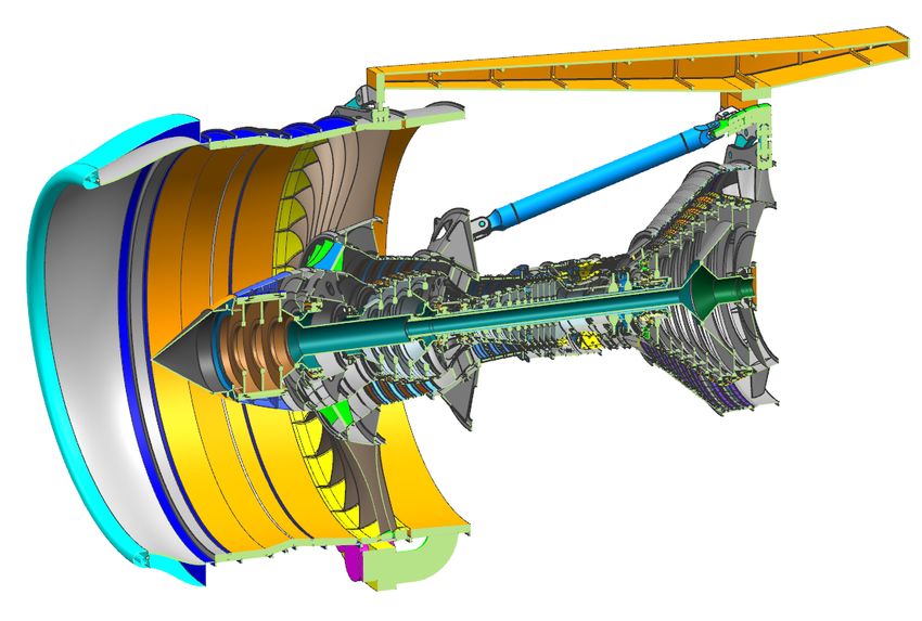
Gas turbine thermomechanical design

• Thermal expansion of the mechanical parts of the engine changes seal clearances
• Seal clearances affects thermal cooling flows and thus part temperatures
• Non-optimal seal clearances affect engine performance and life
• This requires a multi-physics model where
 • Cooling flows are modelled as an ‘air system diagram’, a network of 0D-1D
 chambers and flow resistances
 • The air system model provides thermal boundary conditions to a 3D
 thermomechanical FE analysis
 • The ‘air system’ and ‘structural’ models are developed independently
 • A change in one model is not automatically reflected in the other
 • Both require highly-skilled engineers, and a great deal of manual work
Automating the process using Simulation Intent
 ~3hrs in Parasolid ~10 mins ~3hrs

 Cellular Model Seal/Hole Fluid Domain
 extraction Identification Segmentation

 Cellular Model Fluid cavities
 Partition surfaces
Cell_Solid Cell_Interference

Cell_Fluid
 Main_Cavity
Cavities

 VESTA Engine used with permission from Rolls-Royce
Identification of Seal Inlet/Outlet
1 2 3
 • User selects 2 edges Tensor factorisation
 Generate partition
 of a seal inlet and 2
 surfaces
 edges of the outlet.
 • automatic for seal
 • Same operation for
Top and hole)
 any seal
edge • Added manually
 configuration
 three partitions
 (instantiation of seal
 (gaps)
 is automatic)
 Similar entities

 Pair similar
 entities by
 distance

 Bottom edge

 VESTA Engine used with permission from Rolls-Royce
Fluid segmentation
4
 Main Cavity

 Main Gas Path
 C5 C6

 R2
 C1 Cavity
 R1 C4
 + Segmentation surfaces S4
 C1 S1 Seal

 R1 C2 R1 Restrictor

 S3
 S2 C3

 VESTA Engine used with permission from Rolls-Royce
Lanyon building, Queen’s University Belfast

Cellular models as a carrier for simulation data
Trivial example – a tube carrying a fluid

• Domain captured with cellular model
 • Cell hasManifoldDimension 0 .. 3 Thermal and Structural Model
 • IsBoundedBy (relations between cells) of hollow tube with internal
 flow (next slide)
• Simulation attributes can be attached to 0, 1, 2, 3D cells
 • ‘I am standing on the internal wall of the tube watching
 the flow go by at xx m/s. The temperature here is yyoC.’
• Physics captured by hasGoverningEquations relation
 • ‘Ground truth’ is the equations to be solved
• Idealisations captured by hasEquivalentRepresentation
 relations
• Conventional material substance hasA
 • Modulus E
 • Conductivity
 • …

 Hyunmin Cheong & Adrian Butscher (2019): Physics-based simulation ontology: an ontology to support modelling and reuse of data for physics-based simulation, DOI: 10.1080/09544828.2019.1644301
 Flavien Boussuge, Christopher M. Tierney, Harold Vilmart, Trevor T. Robinson, Cecil G. Armstrong, Declan C. Nolan, Jean-Claude Léon & Federico Ulliana (2019) Capturing simulation intent in an ontology: CAD and CAE integration application, DOI:
 10.1080/09544828.2019.1630806
Structural and flow models for a hollow tube

 Flow
 Structural
 4
 hasGoverningEqns =
 8

 Transfer of pressure and
 ( ) temperature BCs through
 common boundary Flow domain
 hasGoverningEqns (Navier Stokes)

 4
 hasGoverningEqns EI = − = −
 4

Tube hasGoverningEqns

 . = − ; = hasEquivalentRepresentation
Lanyon building, Queen’s University Belfast

Finishing up
Conclusions

• Simulation intent can be defined independent of model geometry and topology
 • Makes simulation workflows much more robust

• Cellular modelling, virtual topology and equivalencing for:
 • Linking analysis attributes between different representations
 • Interface management within components and assemblies
 • Managing models of different fidelity and physics

• Streamline CAE workflows by:
 • Using analysis topology and virtual topology operations to ease geometry operations
 • Using Simulation Intent to automate time-consuming pre-processing activities
 • Utilising geometric reasoning and relational learning to facilitate the pre-processing of
 large, complex multi-physics models

• A next generation digital mock-up should incorporate these ideas
Grand Philosophical Musings

• Trevor Robinson, Acknowledgements, “Automated creation of mixed dimensional
 finite element models”, PhD thesis, 2007.
 • To Professor Cecil G Armstrong … “It has been his refusal to accept that some
 things are just not possible which led to many of the topics of work making it this
 far.” …
• A fanatic:
 • One who redoubles his effort when failure is certain
Acknowledgements

• We wish to acknowledge the financial support provided by Innovate UK through
 projects:
 • GEMinIDS (ref 113088): Slides: 16, 21, 31-33
 • Colibri (ref 113296): Slides 22

• We also thank Rolls-Royce for permission to publish this material
You can also read