A Study of Protocols for Low-Latency Video Transport over the Internet
←
→
Page content transcription
If your browser does not render page correctly, please read the page content below
A Study of Protocols for Low-Latency Video Transport
                      over the Internet
                                                  Ciro A. Noronha, Ph.D.
                                                         Cobalt Digital
                                                           Santa Clara, CA
                                                   ciro.noronha@cobaltdigital.com
                                                    Juliana W. Noronha
                                               University of California, Davis
                                                            Davis, CA
                                                      jwnoronha@ucdavis.edu

Abstract - The speed and quality of the Internet links             latency in the order of tens of seconds. For stored content,
available today have made it possible to employ them as            this is acceptable; it is better to have reliable delivery than
broadcast contribution links. However, Internet links              low latency. However, for many broadcast applications,
experience packet loss. The protocols that deal with this          latency needs to be low, and the protocol may need to “give
loss represent a tradeoff between latency and reliability.         up” on packets that cannot be recovered in a given window
This paper investigates two common packet loss recovery            of time.
protocols: Selective Retransmission (also known as ARQ)                 To date, the only standard protocol that satisfies this
and SMPTE-2022 FEC. We start with a statistical                    latency requirement while providing some packet loss
modeling analysis of these two protocols. Next, using an           recovery is SMPTE-2022 FEC [3] [4]. This protocol was
actual encoder/decoder pair, we present a few lab                  not designed to be used on the Internet; its primary purpose
measurement results using a network simulator specifically         was to recover from occasional packet loss on well-
designed for this test, as well as results from an Internet link   managed links. However, due to the lack of options and the
between locations in California and Illinois. We conclude          quality improvements on Internet links, a number of
with guidelines for broadcasters who are considering the           broadcasters have used SMPTE-2022 FEC with some
Internet as a low-cost contribution link, but are concerned        degree of success. However, in general, something better is
with latency and reliability. At the time of this writing, the     required.
Video Services Forum (VSF) has started a working group                  There are a number of proprietary solutions in the
called RIST (Reliable Internet Stream Transport)                   market today that use variants of the well-known Selective
specifically to standardize such a protocol.                       Retransmission technique. These solutions are usually
                                                                   denoted by ARQ (Automatic Repeat reQuest), described in
                     INTRODUCTION                                  many networking textbooks [5]. The ARQ technique is
                                                                   known to work significantly better than SMPTE-2022 FEC.
The speed and reliability of the Internet has steadily                  In this paper, we provide a comparison between
increased over the last few years. Over-The-Top (OTT)              SMPTE-2022 FEC and one standards-based implementation
services are routinely used by millions to watch high-quality      of ARQ, with the objective of providing low-latency
content. It is natural for broadcasters to consider using the      transport over the Internet. The comparison includes a
Internet as a cost-effective means to transmit contribution-       statistical analysis, a lab test with a custom network
grade video between locations, rather than purchasing              simulator, and one actual test over the Internet.
expensive dedicated links. Studios and TV stations all have
Internet access already, so why not use that for contribution
                                                                                    ACCEPTABLE PACKET LOSS
as well?
     The issue with this approach is that Internet delivery is     Even with the advances in the capacity and reliability of the
best-effort (since IP is best-effort), and one cannot set end-     Internet links, they are not yet fast enough to support raw
to-end priorities. Thus, there will be occasional packet           video transmission in an economical way. Therefore,
losses, primarily due to instantaneous congestion. Since           compression is needed, and the better job the compression
what is being transmitted is compressed audio/video, effects       does, the more important the resulting bits become, since
of uncorrected packet loss are quite noticeable.                   the amount of information they contain is higher. In other
     Transport protocols such as TCP can deal with packet          words, all the bits are important, and they must be delivered
loss and provide reliable delivery. However, there is a            with high reliability. Given that packet loss is unavoidable
fundamental tradeoff between reliable delivery and latency.        if there is a latency constraint, it is important to determine
Given enough time, a well-designed protocol can get every          what an acceptable level of packet loss is.
packet delivered. OTT applications, for instance, use HLS               A simple way to determine the acceptable packet loss is
[1] or DASH [2] for delivery; these protocols may impose a         to assume that every packet loss causes a glitch [6]. This is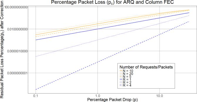
a reasonable assumption with compressed streams because matrix of C columns and R rows. FEC packets are
fundamentally, compression works by removing the computed per column. An optional second FEC
redundancy, and thus every bit is important. In addition, the flow may be computed per row.
effects of a loss may persist for a while, since decoding a The matrix arrangement enables the protocol to
video frame may depend on data from previous video correct burst losses of up to C consecutive packets
frames. In reality, a small fraction of the losses may not be in every group of R×C packets, with an overhead
noticeable or may be concealed by the decoder, but the of 1/R.
more conservative approach is to assume that every loss is a The use of optional row FEC packets enables the
noticeable glitch. protocol to correct single packet losses on each
Based on this approach, it is straightforward to derive row with an overhead of 1/C.
the glitch interval from the data rate and the packet size. The FEC packets for a given matrix are transmitted
Defining: during the next matrix. This makes the latency of
R: stream rate in bits/second this protocol equal to the transmission time of 2RC
B: packet payload size in bytes packets.
p: packet loss probability The protocol is strictly unidirectional. There is no
G: glitch interval in seconds communication from the receiver(s) back to the
The glitch interval is given by (1): sender, so it is well suited for one-to-many
applications.
8B SMPTE-2022 [3] limits R and C to 20 and R×C to
G (1)
100.
Rp
The latency and overhead of this protocol depend on
As an example, let us assume a 4 Mb/s video stream,
the matrix size and the bit rate. Table 2 shows a few
with the usual 1316-byte payload. Table 1 shows the glitch
common operating points.
interval given by (1) at different packet loss rates.
C R Recovery Overhead Latency Latency
Dropping one packet in Produces a glitch every
pkts/block 2Mb/s 10Mb/s
1,000 2.6 seconds
5 5 5/25 20% 263 ms 53 ms
10,000 26 seconds
10 5 10/50 20% 526 ms 105 ms
100,000 4 minutes 23 seconds
20 5 20/100 20% 1052 ms 211 ms
1,000,000 44 minutes
10 10 10/100 10% 1052 ms 211 ms
10,000,000 7 hours 19 minutes
TABLE 2: SAMPLE SMPTE-2022 OPERATING POINTS
TABLE 1: GLITCH INTERVAL AT 4 MB/S
Determining the acceptable packet loss is application- II. ARQ (Selective Retransmission)
specific, and, to a certain extent, subjective. A broadcaster ARQ stands for Automatic Repeat reQuest (or Automatic
may be willing to tolerate more frequent glitches on a live Repeat Query) and is the generic name for a class of
feed from a reporter in the field, but require a stricter retransmission strategies in face of packet loss. The most
standard for a studio contribution link. In any case, the useful technique for video transmission is Selective
acceptable packet loss can always be derived from the Retransmission, where the receiver only sends Negative
desired glitch interval using the method described above. Acknowledgements (NACK) if packet loss is detected. The
sender will then retransmit only the requested packets. This
PROTOCOL REVIEW is illustrated in Figure 1.
I. SMPTE-2022 FEC Sender Receiver
The SMPTE-2022 FEC protocol was designed to correct Internet
occasional packet loss. Its basic features are:
The actual audio/video transfer uses RTP. Network
The protocol adds parity (XOR) FEC packets to Transmitted
packets are
Round-trip
Delay
the stream to handle loss. saved for
A FEC packet protects a group of audio/video possible
retransmission
packets. If there is a single packet loss in this
group, the lost packet can be rebuilt from the
received packets and the FEC packet.
For the purposes of FEC computation, the FIGURE 1: ARQ ILLUSTRATION
transmitted audio/video packets are arranged in a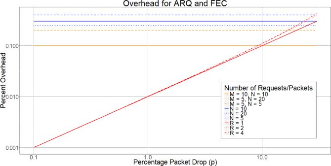
As indicated in Figure 1, the latency requirement for II. SMPTE-2022 FEC Analysis
this protocol is at least one round-trip delay. If multiple In SMPTE-2022 FEC, a group of packets is protected by
round-trip delays are allowed, a dropped packet can be one FEC packet. If there are two or more losses in that
retried multiple times (e.g., when both the packet and its group of packets, then correction is not possible. Finding the
retransmission are dropped). uncorrected packet loss in such a case is simply a matter of
There are a number of proprietary and incompatible calculating the probability of such an event.
ARQ implementations available in the market today. In the following discussion, we will use:
However, for the purposes of this paper, we will consider N: number of rows in the FEC matrix
the variant defined in RFC 4585 [7]: M: number of columns in the FEC matrix
The actual audio/video transfer uses RTP, in the
same fashion as SMPTE-2022 [4]. Column-Only FEC:
Retransmissions are requested using the Generic In Column-Only mode, the FEC packet protects N data
NACK packet from RFC 4585 [7]. packets, provided there is only one loss in the group.
A given packet may be requested multiple times. Therefore, the uncorrected packet loss is given by (4),
which is the probability of two or more losses in the group.
The overhead of the ARQ implementation consists of
the retransmitted packets, and thus is a function of the pc 1 (1 p) N 1 Np(1 p) N (4)
packet loss. In our overhead computations later in this
paper, we disregard the NACK packets since they are
typically very small, and flow in the opposite direction as Since there is one packet added for each group of N
the audio/video traffic. packets, the overhead is simply1:
1
STATISTICAL ANALYSIS OF THE PROTOCOLS H (5)
In this section, we provide a statistical analysis of the N
protocols. We assume that the packet loss process is an
independent and identically distributed process where each Row and Column FEC:
In order to compute the uncorrected loss for the row and
packet is lost with probability p and received with
column mode, we divide the correction process into two
probability (1 - p). In most real networks, the packet loss
process is more complex than this (since packets are usually parts: first, we apply row FEC, and recover whatever
dropped in bursts due to congestion), but this simplified packets are possible. Then, we apply column FEC to the
model allows us to derive useful results. resulting stream. This is how most existing systems
In this analysis, we derive results for the following operate, because the row FEC packet comes immediately
after the block being protected, while the column FEC
variables, as a function of the packet loss probability p:
packets come after the matrix is transmitted. In theory,
pc: uncorrected packet loss (after application of the
protocol) depending on the loss pattern, it may be possible to recover
H: protocol overhead - amount of extra data transmitted to additional packets by iteratively applying row and column
achieve correction, as a fraction of the total transmitted FEC multiple times. However, such a method is not
data required by SMPTE-2022 and we believe that the
improvement is negligible, so it is not included in our
I. ARQ Analysis model.
In ARQ, a packet will remain lost if all of its In order to find the uncorrected packet loss, we simply
retransmissions from the sender are also lost [6]. If we apply (4) twice, first for the row FEC, and then for the
denote the number of allowed retransmissions by R, the column FEC. For a matrix with M columns, the
uncorrected packet loss probability is given by (2), since we intermediate uncorrected loss probability after row FEC is
assume an i.i.d. process. applied is given by (6).
pc p R 1 (2) pM 1 (1 p) M 1 Mp(1 p) M (6)
The overhead is composed simply by summing the The resulting stream is then fed to the column FEC
retransmissions and is given by (3). stage, with an incoming packet loss probability of pM. The
final uncorrected loss probability is then given by (7), with
R pM given by (6).
H pi (3)
i 1
1
In reality, SMPTE-2022 FEC packers are slightly larger than the data
packets, but the difference is negligible and (5) provides a good
approximation of the actual overhead.pc 1 (1 pM ) N 1 NpM (1 pM ) N (7) independent of the packet loss (since FEC packets are
always transmitted regardless of loss). ARQ overhead will
increase with packet loss, but it is lower than FEC overhead
In this case, M column FEC packets and N row FEC packets until the loss is about 10%. As we will show in the next
are added to each M×N matrix, so the overhead is: section, this is past the useful operating point of a FEC
system.
M N
H (8)
MN
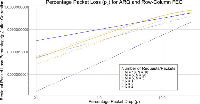
III. Comparison Plots
Plotting the uncorrected packet loss pc as a function of the
input loss probability p is a good way to compare the
protocols. For a given value of p, the protocol exhibiting
the lower pc has better performance.
Figure 2 shows a comparison plot between ARQ with
1, 2 and 4 retries (blue lines) versus column-only FEC with
5, 10 and 20 rows (yellow lines). It shows that ARQ
outperforms column-only FEC for all settings, and that there
is a significant improvement in ARQ performance as more FIGURE 4: PROTOCOL OVERHEAD
retries are allowed.
SIMULATOR TESTS
In order to evaluate the protocols in a lab environment, we
developed a simple network simulator to create a controlled
amount of packet loss. This section describes the simulator
and the tests performed with it.
I. Description of the Network Simulator
As indicated in Figure 5, the network simulator is simply a
software application running on a standard computer. The
simulator receives packets from the encoder and resends
them to the decoder, after imposing a certain amount of
packet loss. At the output of the decoder, there is an actual
FIGURE 2: ARQ VERSUS SMPTE-2022 COLUMN ONLY video monitor connected so the resulting video quality can
be subjectively assessed.
Figure 3 shows a comparison plot between ARQ with
1, 2 and 4 retries versus row and column FEC with 5×5, Encoder Decoder
10×10, and 20×5 matrices. In this case, for some operating
points at low loss rates, FEC can outperform ARQ with 1 or
2 retries. However, at 4 retries ARQ is still superior to
these FEC configurations.
Network
Simulator
FIGURE 5: NETWORK SIMULATOR TEST ENVIRONMENT
The features of the network simulator developed for
this testing are:
The simulator will receive packets from the
encoder and retransmit them to the decoder. It is
aware of SMPTE-2022 packets, and will
automatically forward them to the decoder if
FIGURE 3: ARQ VERSUS SMPTE-2022 ROW AND COLUMN
present.
Finally, the protocol overhead is presented in Figure 4. The simulator will also forward RTCP packets
The SMPTE-2022 FEC overhead is constant and from the decoder to the encoder. This is necessaryfor relaying the RFC 4585 NACK packets in ARQ Input video resolution: 1920x1080i 59.94
tests. Elementary video bit rate: 6 Mb/s
When the simulator decides to create packet loss, it Audio: MPEG-1 Layer II, stereo, 128 kb/s
will drop one or more consecutive packets from the Container: transport stream at 6.877 Mb/s
encoder to the decoder. If the encoder is operating
in SMPTE-2022 mode, FEC packets may also be The protocol parameters were:
dropped; if the encoder is operating in ARQ mode, ARQ: up to 4 retries per packet allowed
retransmissions may also be dropped. SMPTE-2022: 20×5 matrix, row and column FEC
The number of consecutive packets to be dropped
is determined as follows: For this test, we set Lmin = 1 for all trials, and set Lmax to
o The simulator is configured with a different values between 1 and 30.
minimum burst loss, denoted by Lmin, and
a maximum burst loss, denoted by Lmax, The test results are displayed in Figure 6, where we plot
with 1 ≤ Lmin ≤ Lmax ≤ 30. the packet loss at which the video became “not watchable”
o An individual loss drops a random as a function of Lmax. As expected, ARQ produces
number of packets, uniformly distributed significantly better results than SMPTE-2022 FEC. The
between Lmin and Lmax. Therefore, the latter breaks down as soon as the packet loss rate goes over
average packet loss burst is (Lmin+Lmax)/2. about 3%. ARQ, on the other hand, can reliably operate in
The actual loss events are generated at random. the 20% packet loss range, and does better with larger (but
The simulator is configured with an overall packet less-frequent) losses.
loss target, expressed as a percentage of the
packets being forwarded. If we denote the desired
packet loss probability by p, the loss event
probability used by the simulator is given by (9).
2p
PLoss (9)
Lmin Lmax
The simulator was implemented as Windows program
on a standard computer.
II. Test Methodology and Results
Our test methodology was:
Establish an end-to-end real-time flow from
encoder to decoder through the simulator using the FIGURE 6: SIMULATOR TEST RESULTS
protocol under test.
Configure the simulator for a specific burst loss INTERNET TESTS
setting.
We conducted one actual field test over the Internet,
Increase the packet loss rate until, in our subjective
between two Cobalt Digital facilities. For the tests, we used
assessment, the video was no longer “watchable”.
the normal Internet connections for each of the facilities.
Our definition of no longer “watchable” was the
These links were also carrying the normal business Internet
occurrence of noticeable glitches every few
traffic for each facility. The test characteristics were:
seconds.
Endpoints: Santa Clara, CA, and Champaign, IL.
Record this packet loss rate.
ISP (both sides): Comcast
Clearly, that the numerical results for this test will be Network round trip time: 75 milliseconds
highly dependent on the subjective definition of Number of hops: 12
“watchable”, as different viewers will have different Target bit rate: 3 Mb/s
standards. However, if all the tests are performed by the
same viewer, the relative strengths of the two protocols can The tests were performed with actual audio/video data
be assessed. In other words, the absolute numerical results using the same types of encoder/decoder as the simulator
will be viewer-dependent, but useful information can be test.
derived from their relative values.
I. Initial Link Characterization
The tests were performed under the following
conditions: The first step was to characterize the link without any
packet loss recovery protocol. The results are summarized
Compression type: H.264 High Profile
in Table 3.Test Duration 169 hours
Test Duration 25 hours 42 minutes Test Start Date 05/24/17, 12:30PM
Total Packets 26,381,219 Received Packets 173,490,315
Dropped Packets 8,187 Lost Packets 44,606
Packet Loss 0.031% Recovered Packets 44,471
Packet Loss Instances 2,464 Unrecovered Packets 135
Average Packet Drop 3.3 packets Network Packet Loss 0.0257%
Max Packet Drop 169 packets Corrected Packet Loss 0.000078%
Average Glitch Interval 37.5 seconds Correction Ratio 99.7%
Max Error Free Interval 16 min 17 sec Bandwidth Overhead 0.027%
Network Glitch Interval 46 seconds
TABLE 3: INITIAL LINK CHARACTERIZATION Corrected Glitch Interval 4 hours 7 minutes
Protocol Latency 400 milliseconds
The Table 3 results indicate what appears to be an
excellent Internet link, with only a 0.031% packet loss. TABLE 5: ARQ RESULTS – INTERNET LINK
However, the longest, glitch-free interval for this link was
16 minutes in a 25-hour period. On average, there was a
glitch every 37 seconds. The raw performance of this link IV. Discussion
is, by far, unsuitable for a broadcast application, even As predicted by both the analysis and the simulator test,
though by Internet standards it is a very good link. ARQ is far superior to SMPTE-2022 FEC concerning
It should be also noted that the characteristics of a packet recovery capabilities, and this is achieved with a
specific Internet link will change based on time of day and much lower overhead. This is not a surprise, since SMPTE-
day of the week. What is presented here is simply an 2022 was not specifically designed to provide error-free
average of one weekday. operation over the Internet, but rather as an additional
reliability layer for dedicated links (to recover from
II. SMPTE-2022 Test Results occasional packet losses). However, until the RIST group
The SMPTE-2022 FEC test was performed with a 20×5 in the Video Services Forum completes its protocol work, it
matrix, with both column and row FEC. Under these is the only low-latency IP transport that is a standard.
conditions, the protocol can recover a burst loss of up to 20 In the tests shown here, ARQ latency is also lower than
packets every 100-packet block, with an overhead of 25%. that of SMPTE-2022, but this is more an artifact of the
The test results are summarized in Table 4. relatively low bit rates used, coupled with the fact that the
round-trip delay in the test network was not very high.
Test Duration 65 hours SMPTE-2022 latency is independent of the network and is
Test Start Date 05/19/17, 3:50PM inversely proportional to the stream rate, while ARQ latency
Received Packets 67,185,790 will be a function of the network latency. Which method
Lost Packets 10.463 has lower latency will be highly dependent on the
Recovered Packets 8,670 environment.
Unrecovered Packets 1,793
Network Packet Loss 0.0158% CONCLUSIONS
Corrected Packet Loss 0.0027% Broadcasters can use the Internet today as a low-cost
Correction Ratio 83% contribution link for some applications. The questions to be
Bandwidth Overhead 25% asked are:
Network Glitch Interval 1 minute 13 seconds 1. Can the application accept occasional glitches, at
Corrected Glitch Interval 7 minutes 12 seconds the rate of one every few hours?
Protocol Latency 702 milliseconds 2. Can the application accept a transport latency on
the order of several hundred milliseconds?
TABLE 4: SMPTE-2022 FEC RESULTS – INTERNET LINK
If the answer to both questions is yes, then indeed the
III. ARQ Test Results application is a good candidate for transport over the
The ARQ test was performed with a latency setting of 4 Internet, and the advantage is a lower operational cost when
times the round-trip delay, thus allowing for each dropped compared to dedicated IP links. As shown in this paper, the
packet to be retried up to 4 times. The test results are protocols exist to support this application. SMPTE-2022
summarized in Table 5. can potentially be used if the links are of excellent quality
and overhead is not an issue. Alternatively, one of the ARQ
variants can be used for a wider variety of links, still with
acceptable latency. At the time of this writing, the ARQimplementations in the market are not interoperable, but a
standard is being developed [8].
For applications where latency is not a concern, a
transport such as HLS or DASH can be considered as well.
These will have several seconds of latency, but the protocol
is a standard nonetheless and the packet loss performance
will be very good for most networks.
Two aspects not covered on this paper that are
important on an actual deployment are:
Content protection and security: depending on the
content, it may be necessary to use end-to-end
encryption.
Firewall integration: encoders and decoders will be
behind firewalls, which need to be opened enough
for the protocol to operate, or, alternatively, a VPN
must be provided end-to-end.
REFERENCES
[1] Pantos, R., and May, W., “HTTP Live Streaming”, RFC 8216,
August 2017.
[2] ISO/IEC 23009-1, “Information Technology: Dynamic Adaptive
Streaming over HTTP (DASH)”, second edition, 2014-05-15
[3] SMPTE 2022-1-2007, “Forward Error Correction for Real-Time
Video/Audio Transport Over IP Networks”
[4] SMPTE 2022-2-2007, “Unidirectional Transport of Constant Bit Rate
MPEG-2 Transport Streams on IP Networks”
[5] Halsall, F., Data Communications, Computer Networks and Open
Systems, Fourth Edition, 1996, pp 169-170
[6] Noronha, C. and Jia, F., “Live Video Communication over Computer
Networks Using MPEG,” Combined Industry, Space and Earth
Science Data Compression Workshop, Snowbird, Utah, April 4, 1996
[7] Ott, J., Wenger, S., Sato, N., Burmeister, C., and Rey, J., “Extended
RTP Profile for Real-time Transport Control Protocol (RTCP)-Based
Feedback”, RFC 4585, July 2006
[8] Video Services Forum, “Reliable Internet Stream Transport "RIST"
Activity Group”, retrieved from
http://www.videoservicesforum.org/RIST.shtmlYou can also read