Advanced Safeguards Approaches for New TRU Fuel Fabrication Facilities - PNNL-17151
←
→
Page content transcription
If your browser does not render page correctly, please read the page content below
PNNL-17151

Advanced Safeguards
Approaches for New TRU Fuel
Fabrication Facilities

PC Durst   R Bean
MH Ehinger A Dougan
B Boyer    K Tolk
I Therios

December 2007
PNNL-17151

         1
PNNL-17151
Advanced Safeguards
Approaches for
New TRU Fuel
Fabrication Facilities
P. C. Durst, Pacific Northwest National
Laboratory
M. Ehinger, Oak Ridge National Laboratory
B. D. Boyer, Los Alamos National
Laboratory
I. Therios, Argonne National Laboratory
R. Bean, Idaho National Laboratory
A. Dougan, Lawrence Livermore National
Laboratory
K. Tolk, Sandia National Laboratory
Final Report
November 2007
Prepared for the U.S. Department of Energy
Under Contract DE-AC05-76RL01830
Pacific Northwest National Laboratory
Richland, Washington 99352PNNL-17151
Executive Summary 3
1. Background 6
2. Description of TRU Fuel Fabrication Facilities and Processes: 7
2. a. Reference Facility – Plutonium Fuel Production Facility (PFPF) 7
2. b. Reference Facility - J-MOX 10
2. c. Advanced Fuel Cycle Facility – Ceramic TRU (MOX) Fuel Line 11
2. d. Advanced Fuel Cycle Facility – Metallic (Pyroprocess) Fuel Line 15
3. The Current International Safeguards Approach for the Reference Facilities 19
4. Safeguards Approach Options – Ceramic TRU (MOX) Fuel Fab Lines 27
5. Safeguards Approach Options – Metallic Pyroprocessing Lines 29
5. a. Elements of a Safeguards Approach for Pyroprocessing Fuel Fab 29
5. b. Pyroprocessing Safeguards Approach Options 30
5. c. Metallic TRU-Fuel Fabrication Safeguards Approach Measures 31
6. Safeguards Challenges 33
6. a. Ceramic TRU Fuel Fabrication 33
6. b. Metallic (Pyroprocessing) TRU Fuel Fabrication 34
6. c. Varying Actinide Fuel Composition 36
6. d. Distributed vs. Collocated Facilities 37
6. e. Alternative Nuclear Materials
7. Safeguards Technology Needs and Gaps 38
8. Novel Safeguards Approaches – Possibilities 42
9. Conclusions and Recommendations 45
Appendix-A: 48
Glossary and List of Abbreviations
References 60
2PNNL-17151
Executive Summary
U.S. efforts to promote the international expansion of nuclear energy through the Global
Nuclear Energy Partnership (GNEP) and other Advanced Nuclear Fuel Cycle programs
will result in a dramatic expansion of nuclear fuel cycle facilities in the United States.
Demonstration Facilities, such as the Advanced Fuel Cycle Facility (AFCF), the
Advanced Burner Reactor (ABR), and the Consolidated Fuel Treatment Center (CFTC)
will use advanced nuclear and chemical process technologies that must incorporate
increased proliferation resistance to enhance nuclear safeguards.
The ASA-100 Project, “Advanced Safeguards Approaches for New Nuclear Fuel Cycle
Facilities,” commissioned by the NA-243 Office of NNSA, has been tasked with
reviewing and developing advanced safeguards approaches for these demonstration
facilities. Because a goal of GNEP and other Advanced Nuclear Fuel Cycle programs is
developing and sharing proliferation-resistant nuclear technology and services with
partner nations, the safeguards approaches considered are consistent with international
safeguards as currently implemented by the International Atomic Energy Agency
(IAEA).
This second report in a series of three reviews possible safeguards approaches for the new
transuranic (TRU) fuel fabrication processes to be deployed at AFCF – specifically, the
ceramic TRU (MOX) fuel fabrication line and the metallic (pyroprocessing) line. The
most common TRU fuel has been fuel composed of mixed plutonium and uranium
dioxide, referred to as “MOX”. However, under the Advanced Fuel Cycle projects
custom-made fuels with higher contents of neptunium, americium, and curium may also
be produced to evaluate if these “minor actinides” can be effectively burned and
transmuted through irradiation in the ABR. A third and final report in this series will
evaluate and review the advanced safeguards approach options for the ABR.
In reviewing and developing the advanced safeguards approach for the new TRU fuel
fabrication processes envisioned for AFCF, the existing international (IAEA) safeguards
approach at the Plutonium Fuel Production Facility (PFPF) and the conceptual approach
planned for the new J-MOX facility in Japan have been considered as a starting point of
reference. The pyro-metallurgical reprocessing and fuel fabrication process at EBR-II
near Idaho Falls also provided insight for safeguarding the additional metallic
pyroprocessing fuel fabrication line planned for AFCF.
This study concludes that an effective safeguards approach for the new ceramic TRU-
MOX and metallic TRU-fuel fabrication lines planned for AFCF could be based on
advanced safeguards measures, as have been applied to PFPF, and as planned for J-MOX
in Japan. In principle, it should be easier to safeguard these lines, because of the
relatively low throughput of 1 THM TRU fuel per year per line, compared to the
industrial-scale capacity of PFPF and J-MOX (apx. 40 MTHM and 100 MTHM,
respectively). However, there will be significant challenges in safeguarding both TRU
fuel fabrication lines, because of the experimental and flexible nature of the AFCF, as
3PNNL-17151
well as the complexity of the conceptual fuel fabrication processes (as currently
designed).
This report identifies the technical challenges and development “needs” for safeguarding
these new TRU fuel fabrication processes. Many of the “needs” identified for
safeguarding the new reprocessing processes are relevant here as well, although the TRU
fuel fabrication processes present additional safeguards challenges that differ from the
reprocessing processes. These needs are:
• Develop non-destructive assay (NDA) methods to accurately measure the
plutonium (Pu) and actinide content in TRU fuel fabrication process materials and
finished TRU fuel assemblies. (This is currently complicated by the presence of
other “minor actinides”. These methods should be capable of detecting “partial
defects in accordance with current IAEA criteria, i.e. having an accuracy of
approximately +/-5% total Pu and other actinides.) To demonstrate these methods,
samples of the TRU materials planned for the future facilities will have to be
prepared for testing purposes.
• Many of these NDA methods or systems will need to be designed “in-line” to
measure the materials in the process and during transfer from one fabrication step
to the next, to facilitate the timely verification of nuclear material transfers and the
taking of process inventory. These methods should be amenable to remote data
transmission to permit “remote monitoring” of the facility for more efficient
safeguards. Many of the NDA techniques are dependent on the geometry of the
container or assay station. So, once the assay techniques are selected, the assay
stations or TRU objects to be assayed will need to be “mocked-up” to prove the
techniques.
• Make greater use of automated, unattended/remote monitoring systems for
collecting safeguards data, while cooperating with the facility owner/operator and
national authorities to ensure protection of proprietary information. And develop a
more completely automated and integrated safeguards data collect and review
system for analyzing process and on-line assay data and surveillance imagery to
support verification of the nuclear material transfers, inventory, and operational
status of the facility.
• Establish an active dialogue with the IAEA to negotiate a more flexible
interpretation of the IAEA Department of Safeguards SGTS Policy #20,
concerning the joint use of equipment for safeguards purposes. The current
interpretation is very restrictive and limits the ability of the IAEA to use a broad
range of existing plant instruments because of the supposed need to derive
independent safeguards conclusions from these instruments. It is proposed that
this strict interpretation should be applied only to those instruments of primary
safeguards importance – and not to the extensive array of plant instruments, which
could still provide complementary data of safeguards relevance regarding
operation of the facility.
4PNNL-17151
• Cooperate with the facility owner/operator and national authorities to try to design
safeguards requirements and equipment into the conceptual design at the earliest
stages of the conceptual design of the facility.
• Make the inspection regime more efficient by using randomized short-notice
inspections, applying a “statistical process control” approach to verification of the
reprocessing facilities rather than a scheduled systematic verification of all major
transfers of plutonium-bearing materials. For this kind of approach to be effective
the facility operator would need to declare the major activities involving nuclear
material in advance. It would also be more efficient and effective to apply this
approach on a site, rather than facility level.
• Discuss the novel safeguards approaches presented in this report in an international
forum, and in the most promising cases, test them to determine if they would
improve the effectiveness and efficiency of safeguarding a modern TRU-fuel
fabrication facility.
• The conceptual process schematics for both the TRU-MOX and metallic (pyro)
fuel fabrication processes planned for AFCF are very complex, incorporating a
number of additional acid dissolution, solvent extraction and denitration process
steps – many of which are not normally seen in modern TRU-MOX fabrication
plants. Consequently, there is a need to review these conceptual processes to see if
they can be simplified – for the sake of stable process operations as well as to
facilitate nuclear material safeguards.
• The conceptual process schematics for the processes noted above also do not
indicate dedicated storage areas for Pu and TRU-bearing process materials such as
feed material in process, sintered pellets, fabricated fuel rods, or finished
assemblies. There is a need to review the current conceptual designs to see that
such secure storage areas are designed into the process to facilitate stable process
operation and to provide nuclear material inventory points that will facilitate
nuclear material inventory stock taking.
5PNNL-17151
1. Background
As the United States works to promote the global expansion of nuclear power through its
Global Nuclear Energy Partnership (GNEP) and other Advanced Nuclear Fuel Cycle
programs, the nuclear fuel cycle in the United States is expected to expand substantially.
New facilities will be constructed employing advanced nuclear and chemical process
technologies. In addition, it is envisioned that these new Demonstration Facilities will be
designed to be inherently easier to safeguard and more proliferation-resistant. Two of the
main objectives of GNEP and Advanced Nuclear Fuel Cycle programs are the recycle of
nuclear fuel using new technologies to recover more energy and minimize long-term
radioactive waste, and to reduce proliferation risks through the use of these new
“proliferation resistant” technologies.1 The facilities that will demonstrate this new
proliferation-resistant nuclear fuel-cycle include the Advanced Fuel Cycle Facility
(AFCF), the Advanced Burner Reactor (ABR), and the Consolidated Fuel Treatment
Center (CFTC, formerly called ESD).2
The ASA-100 Project, “Advanced Safeguards Approaches for New Nuclear Fuel Cycle
Facilities,” commissioned by the NA-243 Office of NNSA, has been tasked with
reviewing and developing advanced safeguards approaches for these Demonstration
Facilities. The United States has consistently demonstrated its support for international
safeguards, as evidenced by the US government having over 280 nuclear facilities listed
on the Eligible Facility List (EFL) under its Voluntary Offer (Safeguards) Agreement
with the IAEA. It is likely that these Demonstration Facilities would be placed on this
list as well. Furthermore, the development and sharing of proliferation-resistant nuclear
technology and services is a GNEP and Advanced Nuclear Fuel Cycle cornerstone.
Therefore, the conceptual safeguards approaches developed in this study are consistent
with international (IAEA) safeguards and practices.
This second report in a series of three reviews possible safeguards approaches for the new
transuranic (TRU) fuel fabrication processes to be deployed at AFCF – specifically, the
ceramic TRU fuel fabrication line and the metallic (pyroprocessing) line. Advanced
safeguards approaches for the new reprocessing processes to be deployed at AFCF and
CFTC had been addressed in the first report in this series.3 To date, the most common
TRU fuel has been fuel composed of mixed plutonium and uranium dioxide, also referred
to as “MOX”. However, under the Advanced Fuel Cycle projects being considered,
custom-made fuels with higher contents of neptunium, americium, and curium may also
be produced to evaluate if these “minor actinides” can be effectively burned and
transmuted through irradiation in the ABR. A third and final report in this series will
evaluate and review the advanced safeguards approach options for the ABR.
In reviewing and developing the advanced safeguards approach for the new TRU fuel
fabrication processes envisioned for AFCF, the existing international (IAEA) safeguards
approach at the Plutonium Fuel Production Facility (PFPF) in Japan has been considered
as a starting point of reference. The conceptual safeguards approach developed for the
new J-MOX Facility to be built at the Rokkashomura Site in northern Japan has also been
considered. The pyro-metallurgical reprocessing and fuel fabrication process at EBR-II
6PNNL-17151
near Idaho Falls provided insight for safeguarding the additional metallic pyroprocessing
fuel fabrication line planned for AFCF.
The safeguards objective addressed by the approaches presented in this report is
consistent with the goals of the IAEA; specifically, the timely detection of the diversion
of one significant quantity (SQ) of nuclear material.4 The over-arching objective then is
the detection of the diversion of 8 kilograms of separated plutonium within one month of
diversion.♣ It should be understood from this study that safeguards measures also apply
to uranium, although to a lesser extent, since the uranium used in fabricating TRU-fuel is
“indirect-use” material with a one year “timeliness” detection goal.∗ Since GNEP and the
GNEP demonstration facilities strive to improve proliferation resistance and nuclear
safeguards measures, safeguards may also be applied to alternative nuclear materials
“ANM” in the future, such as neptunium and americium.
Traditionally, safeguards have depended primarily on nuclear material accountancy (e.g.
accountability), supplemented with containment and surveillance. It is well recognized
that safeguards objectives in a facility with a large nuclear material throughput cannot be
met by nuclear material accountancy alone. To address this weakness, the conceptual
approaches considered in this report introduce other safeguards measures in addition to
accountancy that, in combination, will allow the inspecting authority to meet the
safeguards objective.
2. Description of TRU Fuel Fabrication Facilities and Processes
2. a. Reference Facility – Plutonium Fuel Production Facility (PFPF)
The Plutonium Fuel Production Facility (PFPF) is owned and operated by the Japan
Atomic Energy Agency (JAEA, formerly called JNC and PNC) and is located at the
JAEA Tokaimura nuclear site. The facility has a nominal capacity of producing 40
tonnes of plutonium-bearing mixed oxide (MOX) fuels and has been in operation since
circa 1988.5 MOX fuel is a nuclear fuel consisting of a blended mixture of UO2 and
PuO2 ceramic powder. Other MOX-fuel plants have been subject to IAEA safeguards in
the world, but PFPF is a good point of reference, because the safeguards systems in the
facility have been subject to extensive modernization by JAEA with the support of the
national inspectorate, the Japan Safeguards Office (JSGO). Many of the non-destructive
assay systems being considered for the conceptual J-MOX facility planned for the
Rokkashomura Reprocessing Site were developed originally at PFPF. Many of these
systems have been further developed to facilitate remote data transmission, so that the
IAEA could remotely monitor the facility to improve the efficiency of the safeguards
inspection regime – thus permitting remote verification of nuclear material at shorter
intervals than the prescribed timeliness detection goal.
♣
There are currently discussions at the IAEA about relaxing the timeliness detection goal for MOX
material and fuel in a country under “Integrated Safeguards”.
∗
“Direct-use” and “indirect use” nuclear material and their respective timeliness goals for the detection of
diversion are as per the IAEA Safeguards Glossary.
7PNNL-17151
PFPF was designed to produce MOX for light water reactors (LWRs), plutonium-bearing
fuel for the Advanced Thermal Reactor (ATR) Fugen and MOX for the Japanese fast
breeder reactors (FBRs) Joyo and Monju. 6 Consequently, the facility has two separate
ceramic MOX fuel fabrication lines – one for ATR and LWR MOX fuel and one for FBR
fuel. The capacity of the ATR/LWR ceramic MOX fuel line is approximately 35
MTHM∗ and the FBR line is approximately 4 MTHM per year. Both processes use
ceramic MOX fuel technology developed from pioneering work done at the Plutonium
Fuel Fabrication Facility (PFFF) on the JNC Tokai site, which started operation in 1972.
Following the sodium fire at Monju in 1995, PFPF has produced primarily MOX fuel for
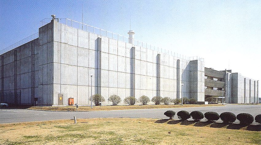
LWRs. A photograph of PFPF is shown in Figure-1 and a simplified process flow
schematic of the ceramic MOX-fuel fabrication process is shown in Figure-2. This
diagram also shows the principle key measurement points for plutonium assay by NDA,
as well as points being considered for containment and surveillance for the new J-MOX
facility.
Figure 1: Photograph of PFPF (Japan)
∗
MTHM is nominally the combined mass of uranium and plutonium in the MOX fuel, expressed in terms
of metric tonnes.
8PNNL-17151
Figure 2: Simplified Process Flow Schematic of
The Pu-MOX Fuel Fabrication Line at PFPF and J-MOX
The following is a simple description of the process. MOX powder produced at the
JAEA Plutonium Conversion Demonstration Facility “PCDF”, or shipped from foreign
suppliers, is received in canisters that contain up to four cans of MOX powder. The
canisters are assayed by NDA and weighed to determine Pu content. The canisters are
placed into a storage vault or unpacked in a plutonium glove box for further processing.
During processing, the plutonium content in the MOX powder is adjusted to the product
specification by blending with depleted uranium (DU). The final plutonium content has
varied in the past from 2% to 30% wt, depending on the fuel produced. The MOX
powder may be milled to improve the physical properties of the ceramic powder. After
blending to the final product specification, the MOX powder is pressed into green pellets
and sintered to a high refractory ceramic oxide pellet that will retain stability and shape
during the high temperature thermal cycling in a nuclear reactor. The sintered pellets are
ground to the final pellet specifications and stored in “pellet boats” in an automated MOX
fuel pellet store. The sintered pellets are removed from the store automatically as needed
and sent to the rod stacking station to be made into MOX fuel rods. The rods are
pressurized with helium gas and the tips are welded closed with an automated tungsten
inert gas (TIG) welder. The rods undergo quality control inspection for nuclear material
content, surface roughness, length, diameter, straightness, etc. and are then stored in the
9PNNL-17151
automated fuel rod storage area. Later these rods are removed from storage and
transferred to the fuel fabrication area to be assembled into finished MOX fuel
assemblies. The MOX fuel assemblies are placed into secured storage or are loaded into
MOX fuel shipping containers and sealed for shipping to Japanese customers. The
receipts and shipments of MOX-bearing materials are subject to verification by the IAEA
using custom designed NDA equipment. The plutonium content of these materials is
determined by gamma spectroscopy and coincident neutron counting. Samples for
destructive analysis are also collected by the IAEA from the process materials as
required. Because the timeliness goal for separated plutonium-bearing materials is one
month, the facility and its inventory of MOX materials is subject to rigorous inspection
by the IAEA once a month. The most relevant aspects of PFPF as a point of reference for
developing a safeguards approach for the new TRU fuel fabrication processes to be
deployed at AFCF are:
• Most stages of the fuel fabrication process are highly automated, and are
completely enclosed in alpha-containment glove box enclosures,
• The key process material storage areas and vaults are highly automated and
“hardened” for physical protection,
• Customized equipment has been designed for assaying the MOX materials in
various stages and containers in the process, through to the final form as a finished
assembly,
• Safeguards NDA and surveillance data collection is typically unattended and is
amenable to remote data transmission,
• Specialized glove box assay systems have been developed to survey work in-
process MOX materials that are still in the glove boxes to determine in process
“hold-up”.
The current safeguards approach at PFPF will be described in more detail in Section-3.
2. b. Reference Facility - J-MOX
Based on the successful operating experience of PFPF, the Japanese commercial
consortium Japan Nuclear Fuel Limited (JNFL) is planning to construct and operate a
large MOX fuel fabrication plant on the site of the Rokkashomura Reprocessing Plant
(RRP), which will be called “J-MOX”. The facility will process and fabricate MOX-fuel
for LWRs using the ceramic MOX fuel fabrication technology employed at PFPF.
However, this facility will be larger, having a capacity of 100 MTHM MOX fuel per year
and will be dedicated strictly to the production of MOX fuel for LWRs and will not
produce MOX fuel for FBRs or for the Japanese ATR Fugen.7 Construction of the
facility is planned for October of 2007, with completion and start-up projected for
October, 2012. The facility will consist of four levels and will process 50% wt. Pu MOX
powder from RRP, blending with depleted or natural uranium to fabricate MOX fuel for
LWRs having a nominal Pu content on the order of 2% – 16 % (of heavy metal). Even
though the J-MOX facility has yet to be constructed and there has been no experience as
yet safeguarding the facility, the similarities with the LWR MOX fuel fabrication line at
PFPF are so similar as to warrant close comparison of the safeguards approaches for the
two facilities. Also, the safeguards approach and equipment that had been developed for
10PNNL-17151
PFPF has evolved further for application at J-MOX – so mention of these evolutions is
worthwhile to consider where the safeguarding of TRU fuels is going.
As stated previously, fundamentally, the MOX fuel fabrication process flow is the same
as that shown in the simplified process diagram for PFPF in Figure-2. The J-MOX
facility will be divided into process sectors according the process operation (powder
processing, pellet processing, scrap processing, rod fabrication and final assembly, etc.).
This will facilitate the performing of short-notice random inspections (SNRI) by the
IAEA to meet the goal of timely detecting possible diversions of plutonium and other
nuclear material. The fabrication process steps are as shown in Figure-2, although there
will be considerable more process equipment than at PFPF to meet the higher fuel
fabrication throughput of 100 MTHM per year MOX fuel. It is also expected that the
facility will be more centrally controlled for process control and nuclear criticality safety.
The J-MOX safeguards approach will be described in more detail along with that for
PFPF in Section-3. However, the most striking features regarding the safeguards
approach is the extensive use of customized NDA equipment for assaying the MOX
process materials and finished assemblies for determining the content of plutonium, the
use of hardened secured locations for storing MOX process materials and finished fuel
assemblies, and the extensive use of containment and surveillance to maintain the
“continuity of knowledge” (CoK) over the MOX materials at all times.
2. c Advanced Fuel Cycle Facility – Ceramic TRU (MOX) Fuel Line
The Advanced Fuel Cycle Facility (AFCF) will be a conceptual research facility to
develop and test new nuclear fuel reprocessing and fuel fabrication flowsheets and
technology.8 The aqueous line of the facility will demonstrate and test aqueous
separations processes that will recover uranium, plutonium, and actinides from spent fuel,
which will then be fed to the fuel fabrication line to be made into advanced transuranic
mixed-oxide (TRU-MOX) fuel. This fuel can be rightly called TRU-mixed oxide,
because it will consist of a mixture of uranium and plutonium-dioxide, as well as
neptunium, americium and curium oxide.♦ One of the goals under the Advanced Nuclear
Fuel Cycle projects is the recycle of the long-term alpha-emitting actinides into fuel
assemblies for burning and transmutation into less long-lived fission products. So, in
principle, the ceramic TRU-fuel fabrication line at AFCF would be another “MOX” fuel
fabrication line and the international safeguards approach and methods that have been
used by the IAEA at PFPF and planned for J-MOX would also be applicable to the
ceramic TRU fuel fabrication line at AFCF. The feed material for the ceramic TRU-fuel
fabrication line will come from the aqueous separations line at AFCF, which will be
designed to process 25 MTHM per year. Initially, as LWR fuel is reprocessed, this will
produce approximately 250 kg Pu per year. At an average TRU content of 25% in the
TRU fuel, this equates to approximately 1 tonne of TRU-MOX fuel per year, initially.
However, the fuel fabrication capacity could be increased if stocks of Pu-MOX are sent
♦
The question of incorporating the minor actinides into the TRU-fuel versus fabricating americium and
curium targets separately is still being considered – although the safeguards measures for both cases would
be comparable.
11PNNL-17151
to AFCF from other storage locations. For the sake of the following discussion, the fuel
fabrication capacity of the ceramic TRU fuel fabrication line is assumed to be on the
order of 1 – 4 tonnes of TRU-MOX fuel per year, with a target to produce up to 8 lead
test assemblies “LTA” for the ABR per year.
A simplified diagram of the ceramic TRU-fuel fabrication schematic for AFCF is shown
in Figure-3.9 However, it should be noted that this has been simplified considerably
from the current conceptual schematic and that several processing steps have been
combined to facilitate a comparison between this TRU-MOX fuel process and the
reference Pu-MOX process depicted in Figure-2.
Figure 3: Simplified Flow Schematic of
Ceramic TRU-MOX Fuel Fabrication Line at AFCF
A summary of the conceptual ceramic TRU-fuel fabrication process planned for AFCF is
as follows: TRU/plutonium product will be removed from the storage vault on site or
will be received from off-site storage. This material will be mixed and combined in a
dissolver to meet the specified transuranic and isotopic content desired for the TRU-
MOX fuel. The mixed TRU material will be blended, dissolved and denitrated and
calcined to a mixed TRU-dioxide. This material will be further blended with UO2 to the
nominal composition of the MOX fuel to be made. The blended TRU-MOX powder will
12PNNL-17151
be milled to the desired particle size and pressed into green (un-sintered) TRU-MOX
pellets. TRU MOX powder, pellets that do not meet specification and other TRU scrap
material will be recycled through a wet-scrap recovery process, or returned to the
aqueous separations (reprocessing) line at AFCF. Green TRU-MOX pellets will be
sintered in a sintering furnace and ground to the final dimensions for the finished pellets.
These pellets will be quality-control inspected and loaded into zircaloy tubes to make
finished TRU-MOX fuel pins (or rods). The fuel rods will also be inspected and
assembled in a fuel fixture to make the final assembly. The finished TRU-MOX
assemblies will be stored in a secured area, awaiting shipment or transfer to the
Advanced Burner Reactor (ABR). TRU-waste and contaminated materials will be
collected and packaged for assay, prior to storage on-site in a TRU-waste storage
location. The safeguards approach and options proposed for this process will be
described in more detail in Sections-4 and 6. In general, the TRU-MOX material will be
weighed and assayed upon being fed to the fuel fabrication process. Containers of TRU-
MOX, containing MOX-powder, pellets, and rods will be assayed by dedicated detectors,
and will be characterized as required by grab samples and destructive analysis (DA). In
simplest terms, the safeguards approach will be verification of the nuclear material
received, verification of the nuclear material fabricated into finished assemblies,
verification of material between major process steps including waste streams, and
periodic verification of the nuclear material in the process inventory. The primary
safeguards focus will be to verify the plutonium, and to a lesser extent the uranium – but
since significant amounts of other actinides will be incorporated into the TRU-MOX fuel,
there will also be a need to verify and account for the neptunium and americium.
The process as described sounds straight-forward, and if the fuel were ceramic uranium
fuel, this would be the case. But the following issues will make the operation and
safeguarding of the ceramic TRU Fuel fabrication line at AFCF more challenging:
• Plutonium and the other actinides are highly radiotoxic and these materials will
have to be handled in completely enclosed gloveboxes. Only after the fuel rods
have been welded, cleaned and inspected is it likely that the nuclear material will
be removed from a glove box (in the form of a fuel rod);
• The final plutonium and actinide composition in the TRU-MOX fuel is highly
variable, depending on the purified nuclear materials available and the
transmutation experiments planned for the ABR. Consequently, it is difficult to
optimize the design of assay equipment to determine the actinide content, if the
composition of the fuel is not well defined prior to development of the assay
equipment (i.e. if you do not know what exactly the nuclear material is, it is
difficult to accurately measure and safeguard);
• There is some experience making experimental assemblies with slightly increased
levels of neptunium, americium and curium and targets of these materials, but not
a great deal of industrial experience – so the fabrication and processing technology
is less developed than for conventional Pu/U-MOX;
• The conceptual ceramic TRU fuel fabrication line flow-sheet for AFCF is
extremely complicated, incorporating a number of dissolution, denitration, and
flexible wet scrap-recovery steps that are not normally part of a dedicated uranium
13PNNL-17151
or MOX fuel fabrication line. These steps may be required, because of the
experimental and flexible nature of AFCF, but such process steps are likely to
introduce operational problems in the fuel fabrication line. Processes that are
subject to frequent shutdown are very difficult to safeguard efficiently;
• The conceptual ceramic TRU fuel fabrication flow sheet does not indicate the
presence of significant MOX-material storage areas, yet it is common practice that
such storage areas are necessary to maintain the process flow. It is likely that
storage areas will need to be created for TRU/Pu feed powder, sintered TRU-MOX
pellets, and TRU-MOX rods. If such storage areas are not provided, there may be
an undesirable accumulation of TRU-MOX materials staged in the glove boxes at
the various processing steps, which could constitute a nuclear criticality hazard, as
well as an increased process hold-up that would need to be regularly verified for
nuclear safeguards.
Regarding the variable fuel composition, the TRU-MOX fuel will be produced from
TRU-product materials recovered in the aqueous separations process at AFCF that is
expected to use a variant of the UREX+ process. Consequently the TRU feed for the
fuel fabrication process may contain any of the elements shown for the TRU
(Reprocessing) Product Stream in Table-1.
Table 1:
Comparison of TRU-Products from the AFCF Separations Line
To be fed to the TRU-MOX Fuel Line
Process Prod. # 1 Prod. # 2 Prod. #3 TRU Product Prod. #5 Prod. #6 Prod. #7
UREX+1 U Tc Cs/Sr TRU + Ln FP
UREX+1A U Tc Cs/Sr TRU All FP
UREX+1B U Tc Cs/Sr U + TRU All FP
UREX+2 U Tc Cs/Sr Pu + Np Am + Cm + Ln FP
UREX+2A U Tc Cs/Sr U + Pu + Np Am + Cm + Ln FP
UREX+3 U Tc Cs/Sr Pu + Np Am + Cm All FP
UREX+3A U Tc Cs/Sr U + Pu + Np Am + Cm All FP
UREX+4 U Tc Cs/Sr Pu + Np Am Cm All FP
Notes: (1) In all cases, iodine is removed as an off-gas from the dissolution process.
(2) Processes are designed for the generation of no liquid high-level wastes.
U: uranium (removed in order to reduce the mass and volume of high-level waste)
Tc: technetium (long-lived fission product, prime contributor to long-term dose at Yucca Mtn.)
Cs/Sr: cesium and strontium (primary short-term heat generators; repository impact
TRU: transuranic elements (Pu: Plutonium, Np: neptunium, Am: americium, Cm: curium)
Ln: lanthanide (rare earth) fission products
FP: fission products other than cesium, strontium, technetium, iodine, and the lanthanides
All FP: fission products plus lanthanides
14PNNL-17151
Regarding waste handling and packaging, the processes are not well defined at this stage
for the AFCF TRU-MOX fuel fabrication line. However, it is believed that the assay
techniques would be comparable to the NDA techniques used at PFPF to assay waste
cubes and TRU-waste drums for plutonium and actinide content.
And finally, the design and construction of AFCF will need to be flexible and adaptable
to accommodate the research and testing requirements specified by the GNEP or other
advanced nuclear fuel cycle programs. Therefore, the facility design will accommodate
changes as required to support the reprocessing experiments. It will also have extensive
remote maintenance capabilities: remotely operated cranes and master-slave or servo-
robotic manipulators and glove-boxes. The flexibility of the facility configuration will be
an additional challenge in safeguarding AFCF, especially when verifying the facility
design information.
2. d. Advanced Fuel Cycle Facility – Pyro (Metallic) TRU-Fuel Line
The AFCF Pyroprocessing fuel fabrication line is still in the early stages of design, but a
simplified schematic of the conceptual process is shown in Figure-4, below. The process
is designed to produce metallic, as opposed to ceramic, TRU fuel for recycle to the
Advanced Burner Reactor. The feed stock will be metal ingots containing transuranic
elements, plutonium and uranium (TRU/Pu/U) from the pyro processing line at AFCF, or
TRU-MOX from the TRU-MOX fabrication line or other storage locations. The facility
will be designed to fabricate 1 THM of fuel per year.
Figure 4: Simplified Flow Diagram of the
Metallic (Pyro) Fuel Fabrication Process at AFCF
15PNNL-17151
A conceptual layout of the pyroprocess and fuel fabrication part of AFCF is shown in
Figure-5, below.10
Figure 5:
Conceptual Layout of the AFCF Pyroprocess
(Pyro-Reprocessing and Metallic Fuel Fabrication Line)
A description of the process is as follows. The metal fuel production concept involves
receipt of casting feedstock to make U-TRU-Zr metallic fuel slugs using an injection
casting process. The current estimate considers 45% TRU, 45% depleted uranium and
10% zirconium. As per the conceptual design, the TRU feedstock would likely come
from the pyro process, but could also come from recovered oxide from the aqueous
process line. The TRU feedstock consists of plutonium, americium, neptunium and
curium, as well as, recycled U-TRU-Zr materials (casting heels, fuel slug end crops, out
of specification fuel slugs, etc.). In the conceptual design, about half of the casting charge
is eventually returned as feed for future castings, since more than half of this recycled
material is the casting heel (material left in the bottom of the crucible after casting).
Uranium and zirconium are added to make up the desired composition. These could be
supplied fresh or recycled from the aqueous recovery process of the AFCF. As noted, the
facility design includes the possibility to receive feed material in the oxide as well as the
metallic form. However, oxide feed material would require conversion to the metal. This
conversion process requires fluorination of the oxide and reduction to the metal form.
From this process, there will be issues with handling additional crucible residues and
casting wastes.
The mixed feedstock is induction melted and injection cast into molds, cooled, removed
from the mold and sheared to length. Three of these fuel slugs would be required to
16PNNL-17151
produce a rod for an ABR lead test assembly “LTA”. The slugs are stacked into a
stainless steel jacket, settled into liquid sodium in the jacket and then the jacket is sealed
by welding. The nearly finished fuel rod is then treated to ensure a good thermal bond is
created between the fuel and the stainless cladding (by the liquid sodium in the fuel rod).
The fabrication process is considered relatively simple and high yields are expected. Poor
yield batches, if they occur, can be recycled in to the casting feed. Shortcomings of the
process, as experienced to date with EBR-II fuel, are that excessive waste is produced
during de-molding and americium is expected to volatilize during the casting process.
The current scheme is to use quartz molds for fuel slug casting. The castings are retrieved
from the mold by breaking the quartz molds. The shards of broken quartz become a waste
stream. The molds, while coated with ZrO2 to prevent interaction between the molten fuel
and the quartz, are also a source of unwanted impurities in the fuel especially in the fuel
heel that remains in the crucible. An important research area is to eliminate the quartz
mold and replace them with a reusable form.
The main points regarding the process that have a bearing on safeguards are:
Varied TRU Feed Receipts: the varied nature of the materials and the varied actinide
content will present challenges for the application of NDA measurements. However,
oxide receipts could be sampled and analyzed by DA techniques.
Assay of TRU-Fuel Pins: individual fuel pins are cast from a molten metal in an
induction heated crucible. The mix in the crucible must be controlled and known.
Sampling and DA analysis of the molten metal in the crucible, along with the net weight
of the melt, would allow verification of nuclear material content. These data could be
supplemented or alternated with NDA verification, but the NDA will be complicated by
the minor actinides present.
Crucible Heels and Waste: it is anticipated that a considerable heel will be left in the
crucible and will be recycled with additional feed material, but there are also concerns
about build-up of contaminates in these heels. Clearly there will be a need to clean the
crucibles, dispose of failed crucibles that may have residual material, and measure the
contents of the crucibles at inventory periods.
Casting Waste: the metal TRU-fuel slug is cast in quartz molds. Upon cooling, the
quartz is shattered to remove the cast fuel slug. The quartz shard is a waste form that will
need to be verified by NDA to determine the amount of nuclear material in the waste.
Feed Oxide Reduction Waste: The process for conversion of the oxides to metal
involves fluorination of the oxides and reduction. This process also produces slag and
crucible wastes. This process will probably handle a variety of compositions from TRU-
fuel to uranium and zirconium feed. The waste will have a variety of characteristic and
composition requiring measurement development.
In general, there is a lot less experience with the metallic TRU fuel fabrication process
compared to the TRU-MOX fabrication process. However, the metallic (pyro) process
17PNNL-17151
was one of the first tested in an Integrated Fuel Cycle Center at the Experimental Breeder
Reactor-II (EBR-II) in the mid 1960’s.11 So, there is considerable process experience
with the process in handling small batches of metallic fuel for recycle to a test fast
reactor. However, there will have to be considerable development effort in safeguards
methods and equipment for this part of this process.
There are however, complications with the metallic fuel process as currently conceived.
First, considerable care will have to be exercised in blending the TRU/Pu/U to the desired
specifications, which could very well vary from batch to batch. Secondly, the
fluorination and reduction process for the potential TRU-MOX feed is a difficult
corrosive process not easily managed in hot cells with remote handling for high-gamma
radiation. Thirdly, the scrap recovery process appears to be very complex, as noted
above. Finally, the metallic (pyro) process itself is a high-temperature process that
normally corrodes the process equipment more aggressively than the TRU-MOX process.
These process and operational issues are noted, because it is more challenging to
safeguard the inventory of nuclear material in a process that is subject to frequent
equipment breakdowns. Nonetheless, the purpose of AFCF is to test and develop fuel
reprocessing and fabrication flowsheets and to assess the “safeguard-ability” and
proliferation resistance of such processes, so it is appropriate to evaluate this at AFCF.
As imagined at this stage, the safeguards approach would be comparable to what has
been discussed for the TRU-MOX fuel fabrication line at AFCF, as noted in the
preceding Section, which will also be discussed in more detail in Section-5.
A more detailed description of the pyroprocess is found in the references noted. 12, 13
Even though the description of the process in those references is for a larger
pyroprocessing line, the process steps at AFCF are expected to be very similar.
18PNNL-17151
3. The Current International Safeguards Approach for the Reference
Facilities (PFPF and J-MOX)
The safeguards approaches for PFPF and J-MOX were developed in the context of an
INFCIRC/153-type comprehensive safeguards agreement concluded between Japan and
the IAEA. The international safeguards approach applied to J-MOX is based
predominantly on the same safeguards criteria and foundation as the approach applied to
the JAEA PFPF plant in Tokaimura.14 This should be remembered when the application
of international safeguards may be in a weapons state under a Voluntary Offer-type
safeguards agreement with the IAEA, such as the United States. Nonetheless, the fuel
processes being considered for new TRU fuel fabrication facilities in the United States
could ultimately be shared with Japan, and conceivably with other nations, where the
application of international safeguards per comprehensive safeguards agreements would
be required.
The safeguards objective for PFPF and J-MOX is the timely detection of the diversion of
1 significant quantity (SQ) of nuclear material.15 The over-arching safeguards objective
then is the detection of the diversion of 8 kg of un-irradiated plutonium within one month
of diversion. Safeguards also apply to uranium, but to a lesser extent.
The safeguards approach for PFPF and J-MOX is based on the traditional approach
applied to all nuclear facilities in accordance with the IAEA safeguards agreement, which
provides for:16
• Defined Material Balance Areas (MBA) for nuclear material accounting
• Defined Key Measurement Points (KMPs) for measuring the flow and
inventory of nuclear material
• Defined Strategic Points for containment and surveillance (C/S) and other
verification measures
• Nuclear Material Accountancy, supported by review of operating records and
state reports
• Annual Physical Inventory Verification (PIV)
• Verification of domestic and international transfers of nuclear material
• Statistical evaluation of the nuclear material balance to determine “Material
Unaccounted for” (MUF)
• Routine, (monthly) interim inventory verifications (IIVs) for the timely
detection of possible diversion of nuclear material
• Verification of facility design information
• Verification of the operator’s measurement system
19PNNL-17151
However, at PFPF it was realized that traditional safeguards measures alone based mainly
on nuclear material accountancy would not meet the safeguards objective, so an approach
was implemented with the following additional operating features and safeguards
measures:17
• An Advanced centralized Accountancy System (AAS) for the plant operator
(JAEA), that can determine the nuclear material inventory within the facility
at key measurement points and process stations to support verification by the
inspectors,
• Hardened secured vaults and semi-automated storage locations for MOX feed
canisters, MOX pellets, MOX fuel rods and finished MOX fuel assemblies,
• An Advanced Containment and Surveillance System (AC/S) that consists of
several kinds of sensors, gamma-detectors, crane monitors, and surveillance
cameras, combined with a super-fast image processing system to detect
changes in the areas under surveillance,
• Continuous, Unattended custom-designed non-destructive assay (NDA)
systems to monitor and determine the plutonium content in the MOX feed
canisters (PCAS), in the accountancy glove box (MAGB), through out the
processing gloveboxes (GBAS), the fuel pin assay station (FPAS), and the
MOX fuel assembly station (FAAS).
• An Advanced Accountancy Verification System (AAVS) that makes use of
near real-time accounting (NRTA) for the purpose of continuously monitoring
the nuclear material in the process.
• PFPF was designed with safeguards and physical protection in mind, being
perhaps the first plutonium processing facility in the world in which the
“Safeguards by Design” concept was implemented.
In essence, the overall safeguards approach at PFPF is as follows: the MOX feed powder
is verified at PFPF upon receipt, using NDA and by weighing the canister. Since the
MOX-bearing materials are relatively clean (virtually no fission products and the amount
of Am-241 is well estimated based on the date of reprocessing), it is possible to
accurately perform this assay based primarily on coincident-neutron counting and gamma
spectroscopy. These receipts are also verified randomly by sampling for destructive
analysis “DA”. This constitutes the plutonium “input” into the facility. Once the MOX
fuel assemblies are fabricated they are verified by NDA and by determination of the
“active fuel length” at the end of the process. Together with the verification of the MOX-
bearing waste materials, this constitutes the facility plutonium “output”. In order to meet
the timeliness goal for detecting a possible diversion of nuclear material within one
month, the facility is inspected by IAEA inspectors monthly. During this time, the
inspectors download the extensive array of unattended NDA and surveillance systems
that monitor feed and process material transfers and compare to the facility operator’s
declarations to verify that all is (or is not) as declared by the operator. To quantify the
MOX material that is not readily accessible in the form of MOF feed, process powder,
pellets, or rods, customized glove box assay systems (GBAS) have been developed that
can be moved into place around randomly selected glove boxes containing large amounts
of MOX materials in process. These systems are very large coincident neutron counting
20PNNL-17151
systems that can be positioned and raised to cover the front and back sides of very tall
MOX process glove boxes. Containment and surveillance systems (redundant video
cameras and electronic and wire seals) are used to monitor the CoK of MOX feed,
materials in the process and finished MOX assemblies. Many such systems are
permanently installed, although some are deployed by the IAEA inspectors specifically to
sequester MOX materials during the monthly interim inspection verifications (IIV) and
annual physical inventory verification (PIV). The inspectors verification of nuclear
material received, shipped, and the resident inventories is further compared with the
national (state) declarations for inventory changes and with the facility operator’s
operating records to determine consistency. Additional safeguards measures such as
periodically verifying the facility design information, collecting environmental samples
and performing “Complementary Access” under the Additional Protocol are also used to
confirm that the facility is being used as declared and that there are no undeclared nuclear
material and/or activities. As a further safeguards enhancement, many of the unattended
NDA and surveillance systems at PFPF have been modified to permit remote
transmission (“Remote Monitoring”) of the safeguards data to the IAEA regional office
in Tokyo for timely evaluation by the inspectors residing in Japan.
The safeguards approach envisioned for J-MOX is very similar in principle to the
safeguards approach applied at PFPF. However, the following enhancements and
additional measures are being incorporated:18
• The process will be divided into sectors to facilitate short-notice random
inspections (SNRI) by the IAEA,
• Extensive use of unattended NDA and surveillance systems will be used to verify
100% of the MOX material flows between sectors,
• More extensive use of video surveillance will be used to monitor key MOX
material storage vaults and areas,
• All safeguards systems will accommodate automated facility operation (i.e. will
not necessitate the operator to shutdown the process monthly to accommodate the
activities performed for monthly verification,
• All MOX materials (MOX feed, process powder, pellets, rods and finished
assemblies) will be measured in the process,
• The safeguards verification system will be unattended, i.e. data for verification of
the MOX material will be collected automatically and remotely transmitted to a
dedicated review station,
• There will be some jointly-shared safeguards equipment,
• All safeguards systems will include features to permit authentication by the IAEA,
including instrument validation, software validation, and validation of data
collected by unattended systems,
• All unattended NDA and surveillance systems will be amenable to “remote
monitoring”, potentially for data transmission to the IAEA regional office in
Tokyo,
21PNNL-17151
• An On-Site Laboratory will process samples for destructive analysis (DA) to
determine plutonium content and to determine potential measurement bias, in a
measurement control program for the on-line NDA measurements,
• Early and detailed declaration of Facility Design Information (DI) by the national
authorities (JSGO) will facilitate design information verification (DIV) by the
IAEA,
• Very close communication between the IAEA, the facility operator (JNFL), the
national nuclear inspectorate (JSGO), and the technical support organization
(NMCC) will facilitate the effective implementation of safeguards,
• A Data Collection and Evaluation System (DC&E) will be provided to facilitate
the centralized integration and initial evaluation of the safeguards data.
A summary of the custom designed safeguards systems being developed and
constructed for J-MOX is shown below in Table-2:
22PNNL-17151
Table-2: Safeguards Equipment Planned for J-MOX∗
Equipment Equipment Name Remarks Provider of
Abbreviation (Quantity) Eqpt.(Supplier)♥
IPCA Improved Plutonium Unattended JSGO (LANL)
Canister Assay System (1) n, γ-Detectors &
ID Camera
IPLC IPCA Load Cell (1) Unattended load cell IAEA
DCPD Directional Canister Unattended IAEA (LANL)
Passage Detector (3) n-Detectors
DMOS Digital Multi-camera Surveillance Cameras IAEA
Optical Surveillance (20 estd.) (Canberra/Aquila)
System (6)
IMCG Inspector Multi-Channel Attended IAEA
Analyzer 2000 with γDetector/Analyzer (Canberra/Aquila)
Germanium Detector (1)
AISV Advanced Inventory Attended JSGO (LANL)
Sample Verif. Sys.(1) n, γ−Detectors
AMGB Advanced Material Unattended IAEA (LANL)
Accountancy Glove Box n,γ−Detectors &
Assay System (9) ID Reader
PSMC Plutonium Scrap Unattended JNFL (LANL)
Multiplicity Counter (1) n-Detectors
GUAM Glove Box Unattended Unattended JNFL (LANL)
Monitoring System (1) n-Detectors
AFPA Advanced Fuel Pin Assay Unattended IAEA (LANL)
System (2) n, γ-Detectors & ID
AFPM Advanced Fuel Pin Unattended IAEA (LANL)
Magazine Assay System n-Detectors &
ID Camera
AFAS Advanced Fuel Assembly Unattended JSGO (LANL)
Assay System(2) n-Detector & ID cam
“SCVS” “Shipping Cask Laser Reflectometer IAEA
Verification System” (1)
WPAS Waste Package Assay Attended JNFL (LANL)
System (1) nDetector/Analyzer
EBAL Electronic Balance (4) Attended JNFL
DC&E Centralized Data Design TBD IAEA
Collection & Eval. Sys.
∗
JSGO is the Japanese Safeguards Office, the national nuclear safeguards inspectorate in Japan. JNFL is
Japan Nuclear Fuel Ltd., the owner/operator of the J-MOX facility.
♥
Supplier of Equipment, where known. LANL is the Los Alamos National Laboratory, in the United
States.
Authentication method for the device to be determined (TBD).
23PNNL-17151
The basic features of the equipment are as noted in the remarks field above. The majority
of the NDA systems used for verifying the plutonium content of MOX materials have
used coincident neutron counting, together with high resolution gamma spectroscopy.
Gamma spectroscopy is used to determine the presence and relative proportion of
isotopes of Pu, U, Am, etc., while the coincident neutron counters are used to determine
the effective mass of Pu-240 present in the material assayed. Having both pieces of
information for a calibrated geometry allows the safeguards inspectors to determine the
total mass of total plutonium and indirectly the amount of uranium and other actinides
present.19 20 21 22 This technique works well for relatively clean MOX and plutonium-
bearing materials. However, this technique becomes challenged when trying to assay
scrap and waste materials. For this reason, the Plutonium Scrap Multiplicity Counter
(PMSC) was developed to more accurately determine the plutonium content in a mixed
matrix such as waste. It is also important to note that the future TRU fuel fabrication
processes that will be discussed for AFCF will have elevated amounts of Am, Np, and
Cm, which will complicate the non-destructive assay, and degrade the assay accuracy as
seen in existing instruments. This point will be discussed in more detail in Section-4 and
6.c.
Regarding the installed NDA equipment for J-MOX, additional equipment is also
identified where needed – such as video cameras to confirm the ID number of the object,
or independent load cells to confirm the gross weight of the container being assayed.
Most of the systems noted in the table above will be installed for unattended operation,
whereby the safeguards NDA data and/or surveillance imagery would be transmitted to
the inspectors shift office at J-MOX for data archiving and evaluation. It is expected that
much of this data will be taken back to IAEA headquarters in Vienna, Austria for further
evaluation – for estimating the “material unaccounted for” (MUF), the difference in
Operator vs. Inspector estimates of MUF (MUF-D), and the running cumulative MUF
(CUMUF). Even though in a modern TRU-fuel fabrication plant such as PFPF and J-
MOX, much of the safeguards equipment is permanently installed, it should also be
remembered that many systems, such as some of the glove box assay systems, can be
moved into position to survey those glove boxes that are randomly selected by the IAEA
to verify the hold-up of MOX materials that cannot be easily containerized and assayed
by dedicated systems. As noted above, it is envisioned that 100% of the process material
transfers will be verified, provided that these materials are in a regular form or can be
placed into standardized containers for assay, such as MOX powder feed canisters, MOX
powder cans, MOX pellet boats, MOX rods (or fuel pins), and finished MOX assemblies.
Although considerable progress has been made in the safeguarding TRU-fuel fabrication
plants such as PFPF, it is important to remember that the TRU-fuel fabrication processes
planned for AFCF will present some very different challenges that will be discussed later
in this report in detail.
Additionally, even though J-MOX is separate and apart from the Rokkasho Reprocessing
Plant “RRP”, there were lessons learned during the start-up of RRP that may also be
24You can also read