Aerospace Telemetry (IRIG 106 PCM & CHAPTER 10 intro)
←
→
Page content transcription
If your browser does not render page correctly, please read the page content below
www.dewesoft.com - Copyright © 2000 - 2021 Dewesoft d.o.o., all rights reserved.

Aerospace Telemetry (IRIG 106 PCM &
        CHAPTER 10 intro)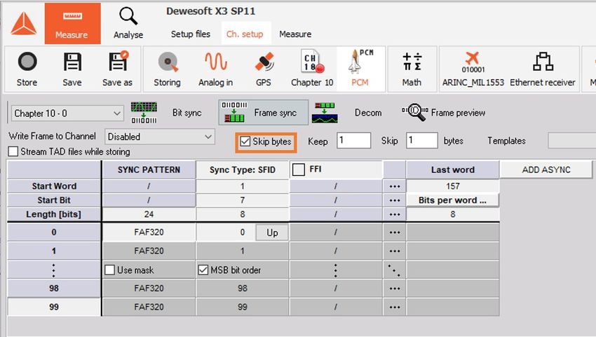
What is Telemetry?
  TELEMETRY is the process in which object characteristics are measured. These measurements result in transmitting
  these results to a faraway station where they are analyzed and displayed.

Telemetering information over wire had its origins in the 19th century. One of the first data-transmission circuits was
developed in 1845 between the Russian Tsar's winter palace and army headquarters. In 1874, French engineers built a system
of weather and snow-depth sensors on Mont Blanc that transmitted real-time information to Paris. In 1901 the American
inventor C. Michalke patented the selsyn, a circuit for sending synchronized rotation information over a distance. In 1906 a set
of seismic stations were built with telemetering to the Pulkovo Observatory in Russia. In 1912, Commonwealth Edison
developed a system of telemetry to monitor electrical loads on its power grid. The Panama Canal (completed 1913-1914) used
extensive telemetry systems to monitor locks and water levels.

Wireless telemetry made early appearances in the radiosonde, developed concurrently in 1930 by Robert Bureau in France and
Pavel Mochanov in Russia. Mochanov's system modulated temperature and pressure measurements by converting them to
the wireless Morse Code. The German V-2 rocket used a system of primitive multiplexed radio signals called "Messina" to
report four rocket parameters, but it was so unreliable that Wernher von Braun once claimed it was more useful to watch the
rocket through binoculars. In the US and the USSR, the Messina system was quickly replaced with better systems (in both
cases, based on pulse-position modulation).

Early Soviet missile and space telemetry systems which were developed in the late 1940s used either pulse-position
modulation (e.g., the Tral telemetry system developed by OKB-MEI) or pulse-duration modulation (e.g., the RTS-5 system
developed by NII-885). In the United States, early work employed similar systems, but were later replaced by pulse-code
modulation (PCM) (for example, in the Mars probe Mariner 4). Later Soviet interplanetary probes used redundant radio
systems, transmitting telemetry by PCM on a decimeter band and PPM on a centimeter band.

                                                                                                                                   1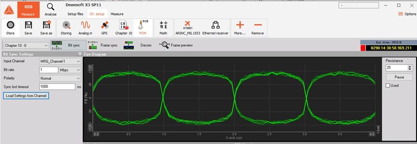
With telemetry, data can be transmitted via air, copper wires, or fiber cables.

If we want to use separate transmission channels for each measured quantity it soon becomes too expensive and very
impractical. That's why telemetry groups measurements into one single format, that can be transmitted as a single data and in
the end separated again into primary components in order to be analyzed properly.

Because of telemetry, we can monitor experiments from a safe distance.

                                                                                                                            2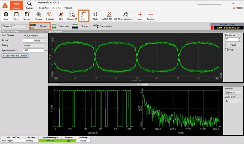
Learn Telemetry Basics
Telemetry is used when standard wireless communication like WiFi data transmission can't be completed because of the
larger distance between the antenna and the observed object. WiFi transmission gets limited really quickly, but with telemetry,
more than 10 billion kilometers have been covered.

The complete telemetry system can be seen in image 2.

As you can see, we distinguish between two sides when it comes to Telemetry:

              Airborne side (rocket, missile, aircraft).
              Ground side (ground station).

                                                                                                                                  3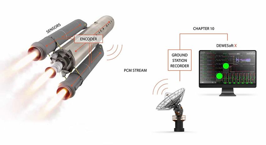
Airborne Side Telemetry System
The airborne side can be Rocket, missile or an aircraft. Let's take a rocket to describe this example.

When we launch a rocket there are many things we need to measure for real-time flight control and for future performance
developments. These measurements can be done with many different sensors (pressure, temperature, acceleration, etc.),
aircraft bus communication (ARINC 429 & Mil-STD-1553), GPS position, Discrete data, Flight computer information, and many
other things.

  ARINC 429 is a data transfer standard for aircraft avionics. It uses a self-clocking, self-synchronizing data bus protocol (Tx
  and Rx are on separate ports). The physical connection wires are twisted pairs carrying balanced differential signaling.

  MIL-STD-1553 is a military standard published by the United States Department of defense that defines the mechanical,
  electrical, and functional characteristics of a serial data bus. It was originally designed as an avionic data bus for use with
  military avionics, but has also become commonly used in spacecraft on-board data handling (OBDH) subsystems, both
  military and civil. It features multiple (commonly dual) redundant balanced line physical layers, a differential network
  interface, time-division multiplexing, half-duplex command/response protocol, and can handle up to 30 Remote Terminals
  - devices.

The role of the PCM Encoder is to measure all these signals in their own unique way. For all the analog channels that make up
a majority of the telemetry data, the PCM Encoder has built-in signal conditioning which provides excitation to each individual
analog sensor (just like our SIRIUS DAQ signal conditioning) and then measures the signal of each sensor. Behind the Signal
Conditioning, the PCM Encoder has A/D converters to measure the input voltages from each sensor and converts it digital
value. There are also special channels on the PCM Encoder for specifically measuring the other unique inputs the Flight
Instrumentation Engineer needs to see from other digital data sources on the aircraft (Aircraft Bus Channels, GPS, and more).

                                                                                                                                    4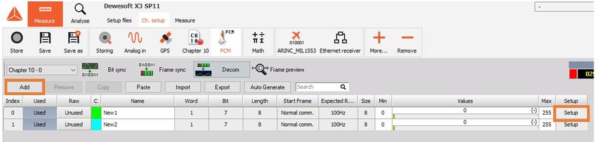
After all of the channels are properly sampled the data moves to the Time Division Multiplexer (also referred to as TDM.) TDM
pulls data from each sensor and creates the PCM Major Frame. The Major Frame can be divided up into Sub Frames or also
called Minor Frames. Each Minor Frame is separated using a Frame Sync pattern (FS). Frame Sync pattern is a known bit
pattern calculated to have a low probability of random occurrence. The Frame Sync pattern usually takes up 2-word locations
for better performance.

  Time-division multiplexing is a scheme in which multiple incoming digital signals are combined for transmission onto a
  single transmission line using interleaved time slots. Each incoming channel is allocated a specific time slot, and has full
  access to the transmission line during its allocated time slot. Some TDM systems allow for a variation in the number of
  signals being sent along the line, and will adjust the time interval of each slot to optimize the use of the available
  bandwidth.

Below is the standard frame sync pattern.

                                                                                                                                 5
When viewing the Major Frame the Frame Sync patterns will be lined up. Traditionally a Sub Frame ID counter channel is
added to the minor frame to know exactly which minor frame you are on in the Major frame.

Different signals acquire different sampling rates in order to keep proper channel resolution. Some signals need to be sampled
more than once per minor frame (vibrations, position) and some of them less than once per minor frame (fuel level). There is a
possibility to optimize our bit rate by sampling all the channels differently. These different types of sampling are referred to as
parameter commutation.

Normal Commutation - signal is sampled once every minor frame

SFID stands for Sub Frame Identifier.

                                                                                                                                      6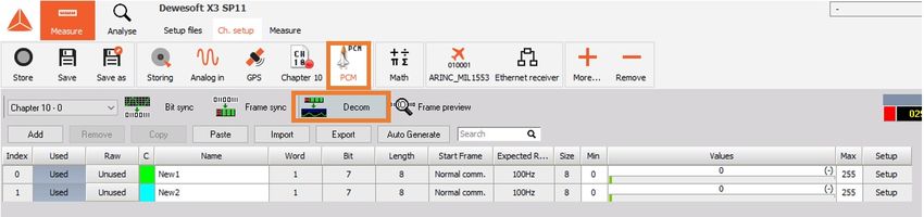
Super Commutation - signal is sampled multiple times every minor frame

Sub Commutation - signal is sampled less than once per minor frame

Random Commutation - signal is sampled randomly throughout the major frame. Not on an even interval in a minor frame or
subframes

Random Normal Commutation - signal is sampled randomly in a minor frame (not on an even interval) but sampled at the
same word location for every minor frame in the major frame

                                                                                                                          7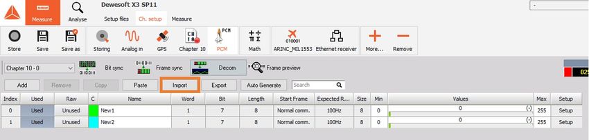
The best way to help visualize this Commutation is by using rotating gear. Signals have different sampling rates, so that
means that they will be sampled at different times.

With Time division multiplexer (TDM) each channel gets sampled for an instant by the multiplexer. When the wheel rotates
for the first time it samples the data from each sensor and writes it to the memory - puts it into the first minor frame. Then the
sequence starts all over again. We need to make sure that it always makes a full lap. This lap needs to be done fast enough in
order to keep the proper sampling rate. Sometimes some sensors need to be sampled at a lower rate than others. In this case,
we use sub commutation and in our rotating gear example, we add a second inner rotating gear. When we have a parameter
that needs to be sampled faster then we can use Super Commutation. This means we will sample it multiple times on our gear
example.

Once our major frame is configured the data is passed along to the PCM Generator. The role of the PCM generator is to take
each minor frame and line it up in a continuous data stream by separating each minor frame with a Frame Sync pattern. The
Frame Sync pattern is used to show the separation of the data so the ground stations can rebuild each minor frame.

                                                                                                                                     8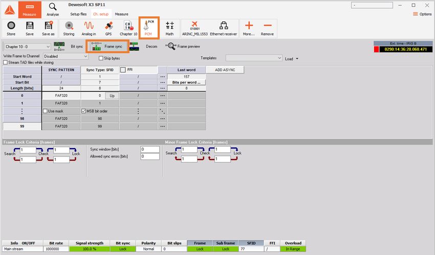
Once the data is in a single row then the PCM code type can be selected. The PCM Code types shown below are ways to
define the analog signal in comparison to a clocking signal. These are designed to allow other hardware to record the Analog
data in a digital format.

                                                                                                                               9
If interested you can find standards on a WSMR SRMY web page.
Next, the data is sent to the RF Transmitter to be sent to the antenna for transmission to the ground. The RF Transmitter will
only put the analog data (dropping the Clocking signal) onto the RF Carrier. The Transmitter will run a low pass filter to smooth
out the data signal that currently looks like a square wave. This filter will make our signal look more like a sine wave to allow
better modulation of the data to the RF carrier. The RF modulation is done using different RF modulation schemes. The most
common is Frequency Modulation (FM) in which the Frequency will slow down or speed up according to the analog data
signal.
Frequency modulation (FM) is the encoding of information in a carrier wave by varying the instantaneous frequency of the
wave.
FM is only one of many modulation schemes used in the Telemetry fields. Other RF Modulation schemes include but not
limited to BPSK, QPSK, and SOQPSK It is beyond the scope of this tutorial to go into detail on exactly how the RF Modulations
works.
Once the data is on the RF carrier the RF signal can be sent to the antenna on the exterior of the rocket to be transmitted to
the ground in real-time. The obstacles and challenges in dealing with the RF world are beyond the scope of this tutorial. Let's
move onto the ground side.
1011
Ground Side Telemetry - Ground Station
Ground Station Diagram

[Video available in the online version]

[Video available in the online version]

                                          12
What is Pulse - code modulation (PCM)?
Analog transmission is not particularly efficient. When the signal-to-noise ratio of an analogue signal
deteriorates due to attenuation, amplifying the signal also amplifies noise. Digital signals are more
easily separated from the noise and can be regenerated in their original state. The conversion of
analogue signals to digital signals, therefore, eliminates the problems caused by attenuation. Pulse
Code Modulation (PCM) is the simplest form of waveform coding.
Waveform coding is used to encode analogue signals (for example speech) into a digital signal. The
digital signal is subsequently used to reconstruct the analogue signal. The accuracy with which the
analogue signal can be reproduced depends in part on the number of bits used to encode the original
signal. Pulse code modulation is an extension of Pulse Amplitude Modulation (PAM), in which a
sampled signal consists of a train of pulses where each pulse corresponds to the amplitude of the
signal at the corresponding sampling time (the signal is modulated in amplitude). Each analogue
sample value is quantised into a discrete value for representation as a digital code word. Pulse code
modulation is the most frequently used analogue-to-digital conversion technique, and is defined in the
ITU-T G.711 specification. The main parts of a conversion system are the encoder (the analogue-to-
digital converter) and the decoder (the digital-to-analogue converter). The combined encoder/decoder
is known as a codec. A PCM encoder performs three functions:
sampling
quantisation
encoding
13Dewesoft X PCM Telemetry Plugin
What is the PCM Plugin?
The PCM Plugin is the plugin that includes the software Frame sync and Decommutation for PCM data
sources. These sources can be from hardware including the Dewesoft Frame Sync box, Chapter 10
Plugin or third-party hardware. The PCM plugin source is only needed so that the Plugin knows where
that data is coming from. As long as its PCM data it is all processed the same by this plugin.
What Does it Do?
This Plugin will do a full software frame synchronization on the PCM data source along with processes
embedded PCM streams. Then the Decom section allows the user to enter individual parameter
information along with the scaling units. Then this data can be combined with many other data sources
brought into Dewesoft X software as long as the time source is all the same.
Where Can I Get It?
The Dewesoft X PCM Telemetry plugin and it's manual can be downloaded and tried for free from our
Download Center -> PCM Telemetry Plugin.
14PCM Telemetry Plugin Setup
How to start?
After the Dewesoft X software has been properly installed, you must set up the PCM Plugin within
Dewesoft X. To do this, please run Dewesoft X. Go to the Settings menu in the top right of the screen
and then select Settings again. When you do this, the Settings dialog box will appear.
Click on the Devices button and you will see the list of all the Devices you can add to your software. If
you open this screen and you do not have anything listed please refer to the steps below. Select the
Chapter 10 and PCM options from this screen.
Make sure you've selected to install all the Addons when running the installer. You can check by
finding your Dewesoft X folder on your hard drive. Then look in the Bin/X3/Addons folder. If this is
empty please re-run the installer.
If your Addons folder has files in it please hit the register plugins at the bottom of the hardware
settings screen. *Note depending on IT restrictions you might have to exit the software and run it as
an administrator.
Locate the PCM plugin in the list and select change the unused to used to activate it. The PCM Card
15source selector gives you the option to choose from No device, Test mode (replay mode), and Tarsus
PCM card, Chapter 10, Dewesoft USB, and iNet:
1. No device - This is for when you have no PCM source at all and wish to see the setup screens
for the PCM plugin.
2. Test Mode - This is an Engineering troubleshooting tool with another ventors binary image file.
3. Tarsus PCM Card - This is for when you have a Tarsus card from Ulyssix Technologies, Inc.
installed and want to process raw PCM data
4. Chapter 10 - This is for when you want the PCM plugin to look at the Dewesoft Chapter 10
plugin for its PCM data source
5. Dewesoft USB - This is for when you are connecting a Dewesoft Frame Sync device.
6. iNet - This is for when you want the PCM plugin to look at the Dewesoft iNet plugin for its PCM
data source
The General settings selector allows you to select several settings to configure the software to your
application.
161. Bit Indexing: allows the user to define the order the bits are counted in the Decom. The options are
15...0, 0...15, or 1...16.
2. Word Count: This setting determines where your frame sync pattern falls in your word count. The
options (FS)1…N means the first word after frame sync is word 1 in the minor frame. (FS)3...N
describes the first word in the frame sync pattern as word 1.
The last thing to set up the software is going to Settings and selecting User interface. Please make
sure that time format is set to Telemetry (UTC).
17PCM Plugin: Bit Sync Configuration
Go to the Ch. setup screen either by clicking the Ch. setup tab in the top toolbar or by pressing F2 on
your keyboard. The setup screen will be shown. Click the PCM tab and then press the Bit sync button.
On this screen, you set up the channel source information. Depending on your data source the options
might change. With the Chapter 10 input source, you will be able to load which PCM channel source
and set up the bit rate unless it is in the TMATs section of your stream. Then you can click the Load
Settings from Channel button. This will set up the data and frame sync information if it is included.
If you are using the Dewesoft Frame Sync box you will need to tell the software a little bit more
information about your stream including bit rate, code type, polarity, etc. The Eye diagram will give you
simulated graphics when looking at chapter 10 and then it will be a scope of the data when working
with any other hardware.
If there are multiple PCM channels sources inside a single system they will run and are set up
independent of each other. Each stream can be selected by the drop-down menu shown below:
18Eye Diagram
This display shows the incoming PCM stream in the classic "eye diagram" graph (Simulated in Chapter
10 mode).
Using the Persistence selector, you can set how many plots are kept on the screen at once. The default
setting is 25 and generally provides the best visual reference. You can increase the persistence to 50
or 100, but this takes more computer memory and also takes longer to update the display. The
recommended setting for most applications is 25.
Use the Pause button to temporarily freeze the eye diagram for visual study. Press this button again to
resume the display updates. The used button allows you to view your eye pattern in a 2D Graph in
measure mode.
19Waveform Diagram
This display shows the incoming PCM stream (Simulated in Chapter 10 & iNet mode) in a conventional
Y/T (amplitude versus time, i.e., oscilloscope type) graph, where the amplitude is shown in percentage,
and time is shown in milliseconds (ms):
You can hover the mouse over the waveform and the display will calculate the amplitude (vertical Y-
axis), the time (horizontal X-axis), and show them numerically at the bottom of the graph.
FFT Diagram
This display shows the incoming PCM stream (Simulated in Chapter 10 & iNet mode) in an FFT
(magnitude versus frequency, i.e., FFT/spectral) graph, where the magnitude is shown in decibels (dB),
and the frequency is shown in Hertz (Hz, kHz, or MHz)
You can hover the mouse over the waveform and the display will calculate the magnitude in dB
20(vertical Y-axis) and frequency (horizontal X-axis) and show them numerically at the bottom of the
graph.
You may select the window type for the FFT display and the zoom level from the drop-down menu.
Rectangular does not influence the FFT decomposition at all, while the other selections are industry-
standard algorithms used for biasing the lobes of the FFT analysis in order to improve the calculations
based on different signal types.
Reference Bar
At the bottom of the bit sync setup screen is a reference bar which shows some important parameters:
The core elements, shown here, are also shown when you change to the other setup screens. These
include:
Info ON/OFF indicates which stream is being monitored.
Bit rate shows the bit rate for the selected stream.
Signal strength shows the strength as a percentage for the selected stream
Bit sync shows the status of the signal lock on the selected stream.
Polarity shows the current polarity (Normal or Inverted) for the selected stream
The headers of the parameters called Bit rate, Sig strength, Bit sync, and Polarity are actually buttons
that can be clicked.
Any of these parameters whose header button is pressed in will become available channels in the
Dewesoft X display screens under the status folder of each card. This allows you to display it on the
screen in a digital meter, status display, tabular display, recorder window, or in any of the graphical
display widgets available within the software.
21PCM Plugin: Frame Sync Configuration
Go to the Ch. setup screen either by clicking the Ch. setup tab in the top toolbar or by pressing F2 on
your keyboard. The setup screen will be shown. Click the PCM tab then press the Frame sync button.
On this screen, you define the framing of the data within the PCM stream including the data length,
frame format identifier, and any asynchronous embedded streams that may be present within the data.
Other important settings include the frame lock criteria of the major and minor frames.
Write Frame to Channel or Stream TAD file while storing – Only use if not in Chapter
10 source. Use these checkboxes to tell the software to automatically archive data to the hard drive in
a TAD (Ulyssix Data format) and/or C10 (IRIG Chapter 10 format if system is licensed) format file when
storing is underway.
22Skip bytes - this checkbox allows you to set a number of bytes to keep and skip, if you have a section
of the PCM data which should be ignored.
When you check the Skip bytes box, two fields labeled Keep and Skip will appear automatically. Simply
click into these fields and enter the appropriate number of bytes. The byte count starts at the first byte
in the frame sync pattern.
Templates - these are a time-saving method of saving a commonly used frame configuration for the
frame sync. If there is a template available under the selector, simply choose it and then click the Load
button in order to make it active.
23Or, to find another template to load, click the down arrow connected to the Load button, and this
submenu will appear.
Moving into the Frame setup table to define the total number of bits in the frame sync pattern from 16
to 33 bits. In image 34, default value was 24 and we have changed it to 32. T o change this value, simply
click into the field and edit the value shown on image 34.
If you are using the IRIG Standard frame sync patterns the hexadecimal value will be automatically
filled in. To change this value, simply click into the field and edit the value.
Select the Use Mask to set up a mask value that will cause the frame sync to ignore certain bits of the
sync word. If using a mask enter a mask value using the following logic rules : logic high or '1' in any bit
position to ignore that bit. For example:
24Sync word size: 32 bits
Sync pattern: FE6B2840 ( in Hexadecimal)
Mask value: 0000F000 ( in Hexadecimal)
This example will cause the Frame Sync to ignore bits 12 through 15 during sync detection. Any value
in the PCM stream where the '2' in the FE6B2840 pattern is located would cause a valid frame lock.
Now enter the number of minor frames per major frame (we have entered 63 in the image 36). Simply
click in the field and enter your number.
Now enter the Last word number in the minor frame (we have entered 160 in the image 37). Simply
click in the field and enter your number. Also, enter the number of Bits per word by clicking in the field
and typing the correct value. We have entered 16 on the image 37. This setting is dependent on the
Word Count setting under the Hardware Setup.
25If your frame definition has variable bits per word simply click on the Bits Per word label. Then the
screen will open below to set up your word size. *Note: you can copy/paste from excel to make entry
easier.
26How to Configure the Sub-Frame Sync?
To configure the Sub-Frame Sync select either SubFrame ID counter (SFID), Frame Code Complement
(FCC) or No minor frame sync (None).
Setup the SFID by entering the number of the word location in the frame of the SFID word . For example, if
you have a 32-bit frame sync pattern with 16-bit words and the SFID is the first word after sync then
the start word is 3.
Then enter the start bit in the SFID word and the total number of bits.
Next, select the word order, up or down, using the toggle button. If it says Up, clicking it will change the
direction to Down, and vice versa. Notice that the numbers will flip around to match your selection. In
the image 40 above, we have selected Up, and therefore the numbers count up from 0 to 63. If we
select Down, the numbers flip around to count down from 63 to 0:
Frame Format Identifier (FFI) word is used to allow the decom hardware to identify a unique pattern in
the PCM stream and perform a format switch.
If your data stream has one or more frame format identifiers (FFI's), you need to check this box and then
enter the integer value corresponding to the word location in the frame , and then enter the word length in
bits, appropriate to your data:
27When you put a checkmark in the FFI box, you will be prompted to enter the integer value of the FFI:
We have entered 129 into the dialog box, and then clicked OK to set this FFI value.
Enter the minor frame in which the FFI starts in the Start frame. For this example, it starts in the first
minor so we enter 0.
Enter the Interval on how many minor frames must go by before we see the FFI again. In this example,
we have a 1 so it will be every minor frame. If we placed a 100 for the interval we would see the FFI
every 100th minor frame.
To add another FFI, use the Add button to create one. The same dialog box will appear allowing you to
enter the value. As soon as more than one FFI exist, you can use the selector to choose among them,
and edit their properties.
28How to Configure the Asynchronous Embedded PCM
Stream?
If your PCM stream contains one or more asynchronous PCM streams, use the ADD ASYNC button to
add each one and then define it.
When you add an asynchronous stream, you must define where it is in the top-level PCM stream. Enter
the starting word and end word by clicking into the fields. If it is not a block of words in between the
Start and end word you can use the Super comm to set up an interval.
Use the ADD ASYNC button to add another asynchronous stream or the DEL ASYNC button to delete
the selected one. With these controls, you may add and manage multiple asynchronous streams.
Dewesoft X can process multiple asynchronous PCM streams at the same time. To set up each
asynchronous PCM frame format use the drop-down menu below to select between the different
streams.
29Frame Lock Criteria
Frame Lock Criteria, i.e., the allowed transitions the hardware requires before changing the frame
status from search -> check, and then from check -> lock. Then the allowed transitions the hardware
requires before changing the frame status from lock -> check, and check -> search. These must be
integers representing a number of frames, and normally low values are used of one or greater.
Sync window (bits) or also known as bit slips are the number of allowed bit errors in your total number
of bits per minor frame.
Allowed sync error (bits) are the number of bit errors allowed in the frame sync pattern to remain
locked to the data
Use the Data In Search Mode selection if the user desires data regardless of Frame Lock.
Minor Frame Lock Criteria, i.e., the allowed transitions the hardware requires before changing the
minor frame status from search -> check, and then from check -> lock. Then enter the number of
allowed transitions the hardware requires before changing the frame status from lock -> check, and
check -> search. These must be integers representing a number of frames, and normally low values are
used of one or greater.
30How to Configure the Decom?
On this screen, you will set up the system to decommutate the PCM stream. It sets up the software to
extract individual parameter data from the PCM stream. The extracted data will be identified,
combined, and processed which will then allow the user to visualize and analyze the PCM data.
Notice the selector which presently says "Main stream" in the image 47. You may use this to select
your asynchronous stream (if defined in the Frame Sync Setup), and the channels from that stream will
be shown on the main display. Click the selector and then choose the desired stream to define
parameters.
The Add/Remove buttons are to add or remove a new parameter to the decom setup.
The Copy/Paste buttons utilize the Windows clipboard to copy selected (the marked or darkened index
number) parameters to the clipboard. The user can then paste these same parameters to other cards
within the same system.
The Import button is for importing Dewesoft X registered parameter lists for easy loading of parameter
setups.
Parameter table heading definitions
31Parameter Description
Index Is the number from 0 to n (the total number of channels plus one) of the parameter
The used/unused status of the scaled output from this channel (when set to "Used", it can be
On/Off
displayed and recorded)
The used/unused status of the raw (unscaled) output from this channel (when set to "Used", it can
On/Off Raw
be displayed and recorded)
Defines the color of this channel. It can be set here by clicking the color icon or on the Channel
C
Setup screen
Name Defines the name of this channel. It can be set here or on the Channel Setup screen
Word Is the word number in the minor frame of this channel
Is the start frame of this channel, will be a number unless the channel is set to "Normal comm"
Start frame
instead of subcom or supercom
Rate Is the update rate of this channel from the Decom Setup
Size Is the bit length of this channel
Values Are a preview of this channel, scaled against the min/max values
Parameter Configuration
This is one of the most important aspects of the system because it is where you define the Parameters,
or "Channels" which are to be extracted and made available for display and recording within the
software.
Note - you can turn on or off the raw and scaled output values from each parameter independently.
Simply click on the Unused button in the same row as the desired parameter to change it to Used,
and vice versa.
Press the Add button to open a new channel setup window or modify an existing channel by pressing
the Setup button at the end of each parameter's row.
32Setting area Setting Description
Enter a name for this channel. This is what will be displayed in the
Name
caption in measure mode.
Description Optionally enter additional info about this channel.
Channel info Units Enter the engineering units for this channel (V, A, degrees, PSI, etc.).
-
Colour Click this windows widget to set the color for this channel.
here you can set up the top-level
properties of the selected Delay Enter the number of milliseconds that this channel is delayed by.
channel. Set the display scale for this channel: low side (This is for Auto Widget
Min value
setting along with Overload indicators).
Set the display scale for this channel: high side (This is for Auto Widget
Max value
setting along with Overload indicators
Note - the min and max values have no effect on the data being recorded. These fields only set the
default display scaling.
Setting area Setting Description
33This is how the data word extracted from the PCM stream is
Decoding and Scaling represented in memory. When Two's Comp or One's Comp is selected,
- the data will be represented as positive and negative values. These
Date Type values will be sign-extended when extracted from the PCM stream. The
here you set up how this channel
is interpreted by the software. Binary selection will treat data as positive binary values with no sign
extension.
Scaling values (A0, A1, A2, A3, A4, A5) you can enter the scaling values according to the formula
shown below the fields, where: A0 + A1 * x + A2 * x + x + A3 * x * x * x ... Enter as many scaling factor
values as you need for this channel; leave the others with the default zeroes in them.
Setting area Setting Description
Commutation
Select from Normal, SuperComm, or SubComm for parameter type.
Type
Used for your SuperComm or SubComm words. For SuperComm words
Interval this is the word interval in between the samples. For SubComm this is
the minor frame interval in between samples.
Here you define:
Start frame - Is the minor frame number the parameter data starts
Start word - Is the word number in the minor frame the parameter
Bit mapping data starts
table Start bit - Is the start bit in the word where the parameter data
starts
Length - (in bits) of the number of bits in the parameter data
34Bit Where you need to combine bits from different parts of the frame to
PCM Frame Location
- Concatenation make one parameter. Ex imbedded Time.
you can set the commutation type Use the [+] and [-] buttons to add indices to the bit mapping table. Then you can click
and bit locations for this channel. within each value in the newly created row or You can also select any index number.
Use the Trigger index if there’s more than one item in a bit mapping table; the user
can select what is a trigger index for writing a sample to a Dewesoft X channel.
Select ET (Embedded Time) to set-up embedded time in the PCM stream as a decom
word. The user can define each BCD time digit to a specific nibble in the PCM word.
Select Synchronous Channel to create a Dewesoft X channel as a synchronous channel,
constant rate.
Select Array channel with channels that have more than one sample (n-m samples, in
most cases it is a vector) and is used for special calculations; for example, Missed
Distance Calculations
A very useful tool to look at the values preview at the bottom of the
dialog to see the effect of your scaling against the real data. It also gives
an overall view of the parameter as you concatenate bits together to
build a parameter.
Values Preview
Use raw and scaled values, these checkboxes serve exactly the same function as the
Used/Unused buttons for the raw and scaled outputs from this channel, back on the
Decom setup screen. You can also set them here using these checkboxes.
35How to Import a Parameter List?
You may import a list of parameters which have already been defined in a TXT, TMATs Files, and CSV
import. Click the Import button as shown here on the decom setup screen:
And you will be presented with the Open dialog box, where you can navigate your computer and locate
the file that you would like to load.
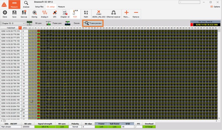
36What does the Frame Preview Screen show?
The frame preview screen gives you a clean look at the raw live frame dump of the major frame data in
hexadecimal. The first minor frame with the minor frame time stamp starts at the top. The channel
color labels show your parameter locations in the major frame.
By clicking on a word in the major frame a window will appear giving detailed information on that
individual word.
If that word is not defined as a parameter select: Add New Channel. This will automatically bring up the
37decom channel setup screen with the correct frame location information filled in.
38IRIG 106 CHAPTER 10 - Digital Recording Standard
A large number of unique and proprietary data structures have been developed for specific data
recording applications that required unique decoding software programs. The activities of writing
unique decoding software, checking the software for accuracy, and decoding the data tapes are
extremely time-consuming and costly.
In the late 1990s, the test ranges started to see the implementation of non-tape-based, high-data-rate
recorders, the most predominant of which were solid-state memory devices. Then, as high-data-rate
digital recorders were fielded and as solid-state technology began to emerge, the Telemetry Group
(TG) saw the need and formed an ad hoc committee for a computer-compatible digital data acquisition
and recording standard.
There is a need for a digital data acquisition and recording standard that supports a broad range of
requirements, including:
Data download and interface
One or more multiplexed data streams
One or more single data streams
Data format definitions
Recorder control
Media declassification
Data interoperability
Specifically, this digital recording standard shall be compatible with the multiplexing of both
synchronous and asynchronous digital inputs such as pulse code modulation (PCM) and MIL-STD-
1553 data bus, time, analog, video, ARINC 429, discrete, and RS-232/422 communication data.
This digital recording standard will allow the use of a common set of playback/data reduction software
to take advantage of emerging random access recording media.
The purpose of this chapter is to establish a common interface standard for the implementation of
digital data acquisition and recording systems by the organizations participating in the Range
Commanders Council (RCC).
This standard does not imply hardware architecture such as the coupling of data acquisition,
multiplexing, and media storage. The required interface levels are contained in this standard.
3940
Dewesoft X IRIG 106 Chapter 10 Plugin
What is the Dewesoft X IRIG 106 Chapter 10 plugin?

The Dewesoft Chapter 10 plugin is a specialized plugin to read a closed recorded data file or
a real-time Ethernet stream of Chapter 10 formatted data.

What does it do?

The Dewesoft Chapter 10 plugin will receive the incoming Chapter 10 data stream from a closed file
playback from the hard drive or from real-time Ethernet stream. The Chapter 10 plugin will then find the
embedded time in the Chapter 10 file to set the Dewesoft master clock too. Then the Chapter 10 Plugin
will look at each data channel included in the data stream to then prepare it for processing. For the Analog,
Video, and Discrete data the Chapter 10 plugin will put it into the proper data channels for processing and
display. It will then hand off the more complex data types like PCM and Arinc429/Mil-1553 data to their
appropriate plugins in Dewesoft for further processing to get to the individual measurement channels.

How to start?

If we want to start we need the following files:

         Dewesoft X Data Acquisition Software. You can download the latest version from
         https://download.dewesoft.com.
         IRIG 106 Chapter 10 plugin for Dewesoft X Software
         PCM Telemetry Plugin for Dewesoft X Software
         Telemetry Camera Plugin for Dewesoft X Software

All the above files can be downloaded from Dewesoft Download Center.

 NOTE: To download beta software, free registration and login is required.

Copy all plugin files under Dewesoft folder Addons. Now you can run Dewesoft X, go to Settings ->
Devices, and add Chapter 10 extension.

                                                                                                           41
In the Chapter 10 Hardware setting there are two modes that the Plugin can run in:
Recorder Mode: This is where the plugin will acquire data from different sources in the software
in real-time. Then Dewesoft X will either record this data to the hard drive of the computer in
a.CH10 file format or can real-time transmit it out the Ethernet stream in a Chapter 10 defined
packet structure for other devices to receive.
Reproducer Mode: This is where the plugin will read in a Chapter 10 format data stream to
process the data within Dewesoft X. The Input Type of Chapter 10 file is to read a. CH10 file
directly from the hard drive of the computer. The other input type of Ethernet: is to bring in the
Chapter 10 Ethernet packet from another device in real-time for processing.
42Then go to Channel setup and go to Chapter 10 tab. This is the screen that appears:
As you can see on the image 62, the file was not found. What we have to do next is to:
A) Select our ch10 file or multiple files (that have the same setup),
This is done by hitting the + button to add files and the - button to remove unwanted files. If using
the multi-file playback then the Up button can be used to reorder the files.
43B) Choose the start and stop position in the file we want.
This is done so use can playback just a small section of the recording. The "..." button will allow
you to set exact times for this. Then uses can replay file at a faster or slower rate. Continuous
Loop Mode is for repeating the Chapter 10 file on a loop for playback checkouts. Fast Playback
will ignore the speed of the recording and once the user hits the store button Dewesoft X will
process the Chapter 10 file as quickly as the computer can to a DXD file.
C) Add or remove channels, Import Channels and Auto-Scan
The Add and remove allow you to manually define channels in your Chapter 10 file. The Import
button will let you load a TMATs file for setup. Then the Auto Scan button will scan the Chapter 10
file for the TMATS built into it to configure the Chapter 10 plugin.
D) Enable wanted channels, change its names or see details in setup. *Note the Time channel must
always be selected when playing back any data type.
NOTE: Packets started to appear in format 0/n, where 0 is the number of error messages out of all
messages.
In this way, we can preview and enable any type of channels like AI, Time, UART, discrete, video data,
and more. The next chapters will show how to do this.
44Analog and Discrete Channels
To enable analog or discrete data packets, we set wanted channels to used:
To present it we go to Measure -> Design mode. We would want to present signals on two different
controls: Recorder for analog signals and Tabular values display for discrete signals. We add it to
wanted place and assign channels to it:
Discrete value channel is displayed in Raw scaling (a); on bottom left (b) Binary format was selected
from the menu on left (c) and on second display (d) Hex format was selected.
45Video Stream
To enable Video stream, add Telemetry video under Add Device -> Camera:
After that, go back to the Channel setup and you will see the Video tab is already generated with PCM
telemetry cameras inside.
46We can preview video stream under Setup. Present a video stream in Measure mode under add Widget
we choose Video visual control and assign the Camera 0 channel to it.
47PCM Stream
First, enable PCM channels:
Now we can show PCM channel values in Measure tab -> Design -> Add tabular display data -> select
PCM Data channel on right. Enable also Raw scaling and Hex format on in the left section:
48Decoding PCM Stream
Dewesoft PCM plugin supports the decoding of the PCM stream.
Go to Settings -> add Device -> and add PCM plugin. Select Chapter 10 as a PCM card.
Click OK, go to Ch. Setup, click PCM icon, select PCM data as Input Channel (it is available if
tetelemePCM channel is enabled in Ch.10 setup) and click Load Settings from Channel button to load
setting from Chapter 10 file (TMATS settings).
Now we can see the Frame sync window:
49To add channel go to Frame preview and click on the PCM frame -> Add New Channel :
New window opens where parameters of the new channel can be set:
5051
Measure

We can view all enabled channels in the Measure tab on appropriate visual control that we can select
and present in Design mode. To visualize wanted channels on the displays, we just click on the names
on the right panel.

Additionally, we can add live mathematics, or in Analysis mode on all channels under Ch. Setup ->
Math.

In the end, stored channels can be exported in various formats that Dewesoft X supports.

                                                                                                    52
You can also read