Assembling a Swarm Navigation System: Communication, Localization, Sensing and Control - DLR
←
→
Page content transcription
If your browser does not render page correctly, please read the page content below
Assembling a Swarm Navigation System:
 Communication, Localization, Sensing and Control
                       Siwei Zhang, Robert Pöhlmann, Emanuel Staudinger and Armin Dammann
         Institute of Communications and Navigation, German Aerospace Center (DLR), Oberpfaffenhofen, Germany
                                          Email: firstname.lastname@DLR.de

   Abstract—Autonomous robotic swarms have attracted increas-
ing attention in recent years due to their enormous, principally
unlimited, capability expansion from single robot systems. A
communication system, as the ‘glue’ in a swarm, plays an
essential role that goes beyond conventional data exchange into
localization, sensing, control, etc. Each building block of a swarm
can be rooted from specific well-addressed research topic such as
communications, signal processing, robotics, control, etc. How-
ever, an interdisciplinary view on swarm communication system,
specially its impacts on other sub-systems, is still missing. In this
paper, we share our experience in the assembling of a radio-based
swarm system, from module design to system integration, from
theoretical investigation to experimental platform development.
With that we aim to shed light on some essential issues when
designing a communication system particularly suitable for
swarms.
                       I. I NTRODUCTION                                 Figure 1: A conceptual swarm lunar mission, where the swarm
                                                                        composes a distributed phased array.
   Environmental monitoring, the search for life or resources,
particularly in inaccessible areas on earth or in space, is still a
challenge today. Exploring huge areas such as the deep sea or              In nature, swarm behavior refers to grouping of numerous
planetary surfaces with a single robotic system often appears to        biological entities, for example bird flocking or fish schooling
be a Sisyphean task or resembles the proverbial ‘search for the         [1]. Each entity, or agent, follows simple interaction rules
needle in the haystack’. To maximize the chances of success of          based on the observation of its surrounding [2]. Yet the
exploration missions, it is necessary to explore unknown areas          whole swarm acts as a single organ with emerging global
on a much larger scale and in comparably shorter time than it           situation awareness and collective behaviors, such as immi-
is done today. A major challenge is navigation and control of           grating, foraging or escaping from predators [3]. Autonomous
the exploration system, since such a system usually operates            robotic swarms, analogous to biological swarms in nature,
in unknown areas, where no navigation and communication                 are self-organized multi-agent systems composed of a crowd
infrastructure is available. Compared to a single robotic sys-          of collaborative artificial entities [4], [5]. Robotic swarm
tem, the application of a swarm of robots for exploration offers        systems attract increasing attention in sensing and exploration
numerous advantages:                                                    applications, e.g. for search and rescue [6], environmental
   1) Redundancy & Reliability: Due to the redundant design,            monitoring [7], and extraterrestrial missions [8], [9]. The size
the entire system can tolerate the failure of individual swarm          of a robotic swarm, referred to either its cardinality or its
elements.                                                               collective aperture’s size, varies depending on the applications.
   2) Speed: Due to parallel exploration the time required for          The cardinality, i.e. the number of agents in the swarm, differs
exploration is considerably reduced.                                    from a few dozens in laboratory demonstrations [10] to a few
   3) Coverage: A swarm is connected by a communication                 thousands in National Aeronautics and Space Administration
mesh network, which enables exploration of wide areas.                  (NASA)’s envisioned deep space exploration missions [11].
   4) Navigation accuracy: Cooperative localization methods             The collective aperture, i.e. the collective area covered by the
based on mutual ranging between swarm elements increase                 swarm, has also a wide range of sizes, from nanometer scale
navigation accuracy.                                                    for nano-swarms implanted inside the human body [12], to
   5) Large observation aperture and accuracy of exploration:           a few hundred meters for planetary surface swarm sensing
The swarm can be used as a large sensor array, which increases          and exploration in both terrestrial [13] and extraterrestrial
the accuracy of observations and enables new possibilities.             applications [14], and to hundreds of kilometers for orbital
   6) Scalability: By controlling the swarm topology, the               applications with a satellite swarm [4].
overall system properties can be adapted to the course of the              As an example, a conceptual lunar swarm mission is illus-
exploratory mission.                                                    trated in Figure 1. A swarm jointly synchronizes and localizes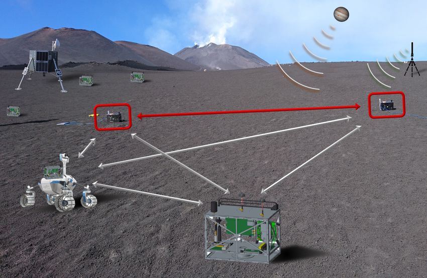
itself with the help of communication links (blue arrows), and              II. R ADIO S IGNALS E XPLOITED BY A S WARM
drives from the mission base (upper left) to a target area. The      A. Position Information in Generic Radio Signals
formation of the swarm is autonomously optimized, compos-
ing a distributed phased array. This array can be used for radio        In this paper, we place emphasis on exploiting radio signals
astronomy as a lunar-based radio telescope network, i.e. low         for swarm navigation. Before diving into the assembling of
frequency array (LOFAR), which senses extraterrestrial radio         a particular swarm navigation system, we first introduce a
signals like the Jupiter’s radio bursts (colored in green). Once     generic radio signal model and present the position informa-
the mission is accomplished, the array’s formation can be            tion embedded in the signal model. Assume a radio signal
readjusted for sensing the radio signal from the lander (colored     sv (t) is modulated onto a carrier ejωt with carrier frequency
in yellow) in order to return to the mission base.                   f and ω = 2πf . This signal is transmitted from an antenna
                                                                     at node v, propagates through the line-of-sight (LOS) path,
   A robotic swarm system consists of several generic building
                                                                     denoted with the index ’0’, and L non-line-of-sight (NLOS)
blocks, which are:
                                                                     paths and reaches an antenna at another node u as
   1) Communication: Data exchange among agents is re-                                                          τuv,l
quired to enable collaborative behavior. The communication                             L
                                                                                       X                    z      }|    {
system’s physical layer (PHY) and media access control layer               ruv (t) =         αuv,l sv (t − (duv,l /c − δuv )) + (t),   (1)
(MAC) with its channel access scheme, and protocols must                               l=0

meet requirements on throughput, latency, etc.                       with the path length duv,l , the relative clock offset δuv , the
   2) Localization: Control algorithms for a robotic swarm           speed of light c, the path delay τuv,l and the circularly-
need to know position as well as orientation of all the agents.      symmetric complex valued Gaussian noise (t). The path
The agents’ position is also required for sensing scalar fields      amplitude αuv,l can be further expanded with real valued
like temperature or vector fields like wind, water currents and      magnitude Auv,l and phase Φuv,l as
electromagnetic field.                                                                                          Φuv,l
                                                                                                          z      }|     {
   3) Sensing: The fundamental task of exploration is the                                              −j(ωduv,l /c − φuv )
                                                                                   αuv,l = Auv,l     e                      ,           (2)
reconstruction of a spatio-temporal process through parame-
ter estimation based on sensed physical quantities. Expected         where φuv denotes the relative phase offset. In principle
process change rates, described by partial first order deriva-       the position information can also be extracted by the path
tives, proportionally set the requirements on accuracy for           magnitude Auv,l and the NLOS components. However, most
self-localization and timing building blocks and determine           radio navigation systems exploit the phase and signal delay
communication latency.                                               of the LOS path, i.e. duv,0 = kpu − pv k, due to their
   4) Control: Control algorithms steering the individual            accuracy and observation simplicity. The notation k·k denotes
agents aim to optimize the exploration progress by, e.g., max-       the Euclidean norm of a vector. The signal delay τuv,0 can
imizing the information gain in each control step. In particular     be directly utilized to estimate the distance between node u
it is important to take safety criteria like collision avoidance     and v, once the clock offset is compensated, for example by
into account when operating in challenging environments.             two way ranging. Extracting distance directly from the phase
   5) Timing: All of the building blocks addressed before need       Φuv,0 is difficult due to the integer ambiguity. Therefore, phase
knowledge about time among all agents with certain accuracy,         difference is often exploited for example in direction of arrival
depending on the speed of exploration and the dynamics of            (DoA) estimation. In this case a multi-port antenna system
the physical process which shall be observed.                        with coherent multi-channel reception, like a phased array or a
                                                                     multi-mode antenna (MMA), is required. It is worth to mention
   In this paper we focus on communication, localization,
                                                                     that once successfully localized, a swarm can be considered
sensing and control out of the building blocks mentioned above
                                                                     as a distributed phased array, which can collaboratively sense
and discuss how to assemble a swarm navigation system from
                                                                     the sources of low frequency radio signals, in applications like
these building blocks. Subsequently, we
                                                                     LOFAR and return-to-base, see Sec. II-D.
  •   introduce the radio signals, which we use for communi-
      cation, ranging and localization,                              B. Self-Organized Channel Access
  •   discuss the observation of low-frequency radio signals as        For a swarm navigation system, it is essential to design
      an example application for a robotic exploration swarm,        a self-organized channel access scheme, which guarantees
  •   provide a method for the estimation of a swarm system’s        accurate localization with a high update rate and low-latency
      state, in particular its agents’ positions and orientations,   data exchange [15]. The widely applied opportunistic access
  •   address the principle of swarm control, which we use in        schemes like the carrier-sense multiple access with collision
      our swarm system,                                              avoidance (CSMA-CA) is not suitable for a swarm. The
  •   show the evolution of our experimental swarm system            increasing back-off time in CSMA-CA may lead to an un-
      platforms and                                                  bounded latency, which is unacceptable for both localization
  •   present selected results regarding swarm navigation per-       and data exchange. Self-organized time-division multiple ac-
      formance.                                                      cess (SOTDMA) is preferable for a swarm navigation system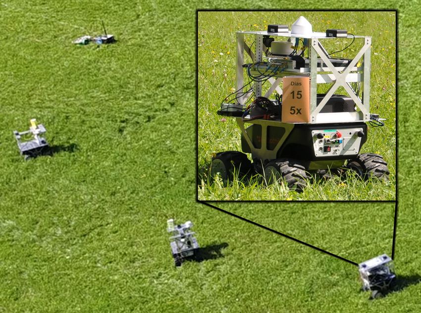
the swarm in conjunction with spatio-temporal correlation of
Activity process parameters, and the used low-cost clocks. Distributed
Agent 19
Agent 0
Agent 1
Agent 2
Agent 3
Agent 4
Agent 0
algorithms often require iterations among agents to converge,
and hence, the radio channel must be accessed frequently. We
designed the MAC for a network update rate of 100 Hz for 20
agents, resulting in slot lengths of 500 µs. Figure 2 shows the
Time
TDMA framing. Each agent has interference-free access on the
11 OFDM symbols radio channel for broadcasting, and self-synchronizes its own
transmission slot relative to TDMA slots of its neighbors. With
GT CP Preamble CP Data ... CP Data
this approach, no central master providing slot-boundaries is
required, and a single-point of failure is removed from the
Time
network.
Frequency In a second step we designed the PHY based on OFDM,
... ... ... ... which is driven by the expected radio channel characteris-
Preamble
... ... ... ...
...
...
...
...
...
...
...
... tics, maximum carrier frequency, and swarm mobility. The
... ... ... ...
...
...
...
...
...
...
...
... 10 Data maximum carrier frequency is 5.9 GHz and the expected
maximum relative speed among agents is 100 km h−1 . Radio
... ... ... ...
...
...
...
...
...
...
...
... symbols
... ... ... ...
propagation models based on channel-sounding measurements
Guard band Scattered pilots for carrier frequencies above 1 GHz are not available for lunar
922 allocable subcarriers and Martian surfaces. Therefore, we take reference in vehicle-
1024 subcarriers to-vehicle, air-to-air, and air-to-ground channel models in the
Time 5 GHz frequency band in hilly terrain environments and define
a maximum expected radio channel excess delay of 2 µs. The
Figure 2: TDMA and OFDM signal structure with GT as TDMA slot
final OFDM system parameters yield 1024 subcarriers for a
guard time and CP as cyclic prefix.
system bandwidth of 25 MHz, 2 µs of cyclic-prefix length, 11
due to its interference-free exclusive bandwidth (BW) occu- OFDM symbols per TDMA slot, and a TDMA slot guard time
pation, which is advantageous for localization. In addition, of 6.76 µs to take a maximum distance of 2 km between two
once a time-division multiple access (TDMA) structure has agents into account. Only 90 % of the system bandwidth is
been setup, the latency is upper bounded by the TDMA allocated resulting in guard bands at the spectrum’s edge to
frame length. Conventionally, an SOTDMA structure, like take filter responses of radio frequency (RF) signal chains into
used in the automatic identification system (AIS) in maritime account. The number of allocable subcarriers is therefore 922.
communications, is setup with a fixed slot length and frame The first OFDM symbol is an agent-specific preamble based
length. Therefore, it is suitable for a swarm with a relatively on Zadoff-Chu codes and is used for frame-synchronization,
stable topology and long duration signals like the orthogonal agent-identification, channel estimation, precise ranging and
frequency-division multiplexing (OFDM) signal in 3rd genera- clock tracking. Preambles are designed for differential corre-
tion partnership project (3GPP)-long-term evolution (LTE). An lation resulting in low processing effort to maintain the TDMA
SOTDMA frame structure can alternatively emerge with the frame structure. The following 10 OFDM symbols can be
concept of pulse coupled oscillator (PCO) [16]. In the PCO- freely allocated for data transmission, where a state-of-the-art
based SOTDMA, the TDMA slot length is inherently adaptive, (s.o.t.a.) 3GPP-LTE or 5th generation mobile networks (5G)
suitable for changing topology and splitting and rejoining of coding and modulation scheme can be used. For ranging and
swarms. It is suitable for impulse radio used by ultra-wide localization we dedicate up to 3 OFDM data symbols with a
band (UWB), but sub-optimal for signals with long duration. very strong forward error correction (FEC). Automatic repeat
In our current swarm navigation system, OFDM signals similar request (ARQ) schemes are not applicable for ranging and
as in LTE are designed for inter-agent communications and localization data, as the information broadcasted by one agent
ranging. Therefore, we applied an SOTDMA similar to the in one TDMA slot is already outdated in the next TDMA
conventional one to enable self-organized channel access. frame. Hence, data related to ranging and localization must
be decoded error-free under the worst reception conditions.
C. OFDM Signal for Swarm Synchronization and Ranging However, ARQ schemes can be used for time-insensitive
Our overall design is driven by the following aspects: data transmission in the remaining OFDM symbols. The last
Spatio-temporal characteristics of sensed processes, the ex- OFDM symbol contains scattered pilots used for 2D-filtering
pected radio channel on a lunar or Martian surface, mobility of the channel transfer function for all data symbols.
of agents, properties of available light-weight software-defined
radios (SDRs), robustness against agent failures, and a simpli- D. Sensing Low-Frequency Radio Signal
fied interfacing for its usage in the robotics domain. We have identified two use-cases for sensing a low-
In a first step we designed the MAC driven by the distributed frequency radio signal within a carrier frequency range of
algorithms for self-localization and sensing, the mobility of 1 MHz to 100 MHz with a robotic swarm: a LOFAR and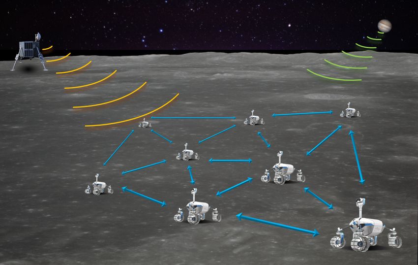
return-to-base navigation, as illustrated in Figure 1. Both uses-   where p/u is the positions of agents other than u and zvw is
cases demand a high self-localization accuracy in the order of      the measurement between agents v and w. Due to cooperation
decimeters, a high time-synchronization accuracy in the order       among agents, a 2(|A|−1) dimensional integral is needed for
of nanoseconds. A LOFAR is a distributed phase-coherent             an exact decentralized Bayesian estimator of pu , which makes
antenna array for radio astronomy. Such an array shall be           it impracticable. A popular approach to reduce the complexity
placed on the lunar far-side to observe the radio-sky without       of marginalization is belief propagation (BP), for example the
man-made interference and will consist of dozens to hundreds        SPAWN algorithm [19]. In SPAWN, an agent u approximates
                                                                                                                                 (K)
of distributed antenna elements. In return-to-base navigation       its marginalized a posteriori pdf p(pu |z) by the belief bu ,
a robotic swarm shall navigate back to a lander through             which is updated by exchanging belief with neighbors Au for
observing a low-frequency radio beacon. Swarm control is key        K iterations
for this use case: the robotic swarm must span a distributed                      Y ˆ
antenna array with optimal relative positions to jointly achieve    b(k)
                                                                      u  =  b (0)
                                                                              u         b(k−1)
                                                                                         v     p(zuv |pu , pv ) dpv k = 1, · · · , K.
highly accurate self-localization and radio beacon source lo-                   v∈Au

calization.                                                                                                                          (4)
                                                                    The SPAWN reduces the complexity to |Au | integrals with
            III. S TATE E STIMATION IN A S WARM                     four dimensions for each agent at each iteration. Depending
                                                                    on the distribution model, the marginalization in (4) can be
A. Swarm Localization                                               realized by Monte Carlo integration as in non-parametric belief
   A brief survey on network localization is provided in [17],      propagation (NBP) [20], by numerical integration for example
which can be generalized to a wide range of specific applica-       in cubature belief propagation (CBP) [21], or analytically with
tions including swarm self-localization. In particular for swarm    parametric belief propagation (PBP) for special distributions
localization, we are interested in decentralized localization       [22]. For the highly non-Gaussian and non-linear models in-
algorithms suitable for large-scale dense networks with high        volved in localization, NBP is often applied [23]. The proposed
reliability and low complexity. There are two major challenges      DiPNet is a variant of BP, where non-parametric belief is
in designing decentralized swarm localization algorithms: (1)       updated locally and only the first two moments of the belief
                                                                     (k)
incorporating neighbors’ position uncertainty while remaining       bu are broadcasted to the neighbors. In order to further reduce
low complexity, and (2) minimizing the stochastic propagation       the complexity, we propose a belief update based on the Fisher
effects, e.g. multipath and NLOS propagation. We proposed an        information (FI) theory. Hence, the mean square error (MSE)
algorithm dubbed direct particle filtering for decentralized net-   matrix Cp̂ of the position estimate p̂ can be assessed by the FI
work localization (DiPNet) in [18], which explicitly conquers       in snapshot case, and the Bayesian information (BI) in tracking
these challenges. DiPNet adapts the sum-product algorithm           case, i.e.
over a wireless network (SPAWN) algorithm introduced in                                        Cp̂ < I−1
                                                                                                      p .                        (5)
[19] to account for position uncertainty of neighboring nodes,      We denote either the position FI or BI by Ip to include
with further reduced complexity. In addition, it exploits the       both snapshot and tracking cases. With the help of FI, the
concept of direct position estimation (DPE), directly consid-       so called equivalent measurement likelihood (EL), denoted as
ering the received signals as measurements, instead of taking       p̃(k−1) (zuv |pu , pv ), can be found. The belief update can then
the range measurements as in traditional two step localization      be simplified as
algorithms. This approach exploits the advantage of a swarm,                          Y
that is a single measurement failure can be collaboratively cor-        b(k)
                                                                         u = bu
                                                                                 (0)
                                                                                            p̃(k−1) (zuv |pu , pv ) k = 1, · · · , K. (6)
rected by the highly redundant measurements. The propagation                        v∈Au
effects on DiPNet become insignificant for dense networks,          The concept of EL can be applied to two-step localization [24]
due to the multi-link collective PHY layer signal processing.       or to DPE as in DiPNet.
Consequently, DiPNet achieves a near-optimal performance
with low complexity, which is particularly attractive for re-       B. Swarm Attitude Estimation
altime dense-network localization.
                                                                       The attitude of a robot can be represented by the three
   Next, we provide a compact description of DiPNet and refer
                                                                    Euler angles roll, pitch and yaw. Knowing them is essential
the interested reader to [18] for more details. Assume a swarm
                                                                    for control, e.g. to drive in a certain direction, but also for
A with |A| agents at positions p = vec{pu : u = 1, · · · , |A|}.
                                                                    placement of sensors, manipulation etc. While roll and pitch
An optimal decentralized Bayesian localization at agent u
                                                                    can be determined from the gravity vector, which is measured
estimates its own position using the marginalized a posteriori
                                                                    by accelerometers, estimating yaw is more challenging. Start-
probability density function (pdf),
                                                                    ing from a known yaw, the relative changes could be obtained
                     ˆ              |A|
                                    Y                               by integrating the turnrate measured by a gyroscope. However,
  p(pu |z) ∝ p(pu ) p(p/u |pu )          p(zvw |pv , pw ) dp/u ,    due to drifting sensor biases, this leads to a quickly growing
                                  v,w=1                             error over time. On earth, the magnetic field could be used to
                                                             (3)    determine the yaw. For extraterrestrial exploration, this is in
general not an option, as e.g. Moon or Mars do not have a Similarly as in VI-A, the position MSE matrix is evaluated
dipole magnetic field like the earth. with FI or BI. With the causality awareness, the swarm
Instead, in our approach we estimate the yaw based on can actively optimize its position minimizing the uncertainty,
the DoA of received radio signals, i.e. azimuth γuv,l and which is referred to as information seeking swarm control.
elevation θuv,l of the impinging signal. Classically, phased The information seeking can be formulated as a cost function
antenna arrays are used for that purpose [25]. A phased array (+) −1
ΛIp , which is minimized with best effort. This type of
typically consists of multiple identical antenna elements in a information seeking is preferable in, e.g., low frequency source
certain arrangement, often with uniform spacing. Depending localization, where the source is considered as a special node
on the direction, an impinging signal arrives with slightly in the extended swarm network. Alternatively, the information
different phase at the different antenna elements. For low- (+) −1
seeking can be expressed as constraints, Emax −Λc Ip < 0,
power devices, another approach is to use multiple directive
where Emax is the maximally tolerated position error. This
antennas, and compare the received signal strength indicator
type of information seeking is suitable for, for example,
(RSSI), i.e. the signal power [26], [27]. Recently, MMAs
limiting the position error of the agents. In addition to the
have been proposed as a new approach for DoA estimation
information seeking, other mission cost functions f (b), like
[28]. They are designed based on the theory of characteristic
return-to-mission base, or constraints h(b) ≥ 0, like collision
modes, where each mode is excited independently. For an
avoidance, can be considered. The overall control objective of
MMA, the direction information is contained in both power
the swarm can be expressed as
and phase of the signals. First measurements results with an
−1
MMA prototype mounted on rover are presented in [29]. All minimize { diag{ΛI(+)
p } , f (b) } (10a)
b
three antenna types can be described by their antenna response −1
q s.t. Emax − Λc I(+)
pTable I: Evolution of our swarm navigation testbed. Table II: Our experimental activities.
Gen. Hardware Protocol Metrics Data Year Gen. Environment New features
TDMA, 2015 1.0 Grass field DiPNet
1.0 Custom FPGA Range no
unicast
2018 2.0 Gravel pit Real-time DPF
Single-channel SOTDMA,
2.0 Range yes 2018 2.0 IAC (indoor) Larger BW, payload box
SDR broadcast
2019 2.0 Mt. Etna (volcano) Scouting, first tests
Single/multi- SOTDMA,
2.1 Range, DoA yes 2020 2.1 Grass field DoA, ROS
channel SDR broadcast
2021 2.1 Mt. Etna (volcano) LOFAR
GNU Radio ROS
RX Raw
L/C-band samples ecosystem
Frame sync, VI. S ELECTED R ESULTS
FFT, CFO comp.
Inertial sensors Throughout the the evolution of the swarm navigation sys-
DoAs
DoA estimation tem, we have conducted numerous measurements and demon-
USRP Odometry strations. The most important milestones are summarized in
ToA estimation Table II. In 2015, we made measurements with the first version
of the system, where DiPNet was evaluated. In 2018, as a final
Demodulation, Data Decentralized PF project demonstration, six rovers navigated in a gravel pit for
Decoding gas source exploration. A real-time version of the DPF was
Position,
Clock tracking, Ranges implemented for that purpose. In the same year, we demon-
(Orientation)
2-way ranging strated the system indoors at the International Astronautical
Control Congress (IAC) in Bremen, Germany. The BW was increased
TX
Coding, Data and the hardware was integrated into space analogue carbon
Modulation Logging fibre payload boxes, which can be manipulated by a robot
SOTDMA
[31]. In 2019 a scout mission took place on the volcano
scheduling Visualization Mt. Etna in Sicily, Italy. In 2020, we integrated a multi-
HF/VHF
channel SDR and an MMA into our experimental platform
Snapshot RF sensing (generation 2.1), which enables real-time attitude estimation.
USRP
processing LOFAR A LOFAR demonstration as part of a space-analog mission
Optional [31] was scheduled in 2020, but shifted to 2021 due to the
Figure 3: Overview and flow-graph of the swarm communication, COVID-19 pandemic.
navigation, and timing system.
A. DiPNet Performance on Grass Field
calculate the RTT for distance estimation. On the transmit side, We conducted an outdoor experiment with six swarm nav-
we implemented the necessary coding and modulation, and the igation testbeds (generation 1.0) on a grass field in 2015
MAC for SOTDMA scheduling, which is closely coupled with [18]. Five stationary testbeds were placed in a pentagonal
the PHY. formation and the sixth testbed was mounted on a remotely
A challenge besides the design of the SDR architecture, controlled rover. The received OFDM symbols of 9900 unicast
PHY and MAC has been the interfacing into the other swarm two-way measurements from 330 snapshots were collected.
subsystems, and hence, into the robotics domain. We utilize The rover was driving smoothly with a moderate velocity
the robot operating system (ROS), which is a commonly used until snapshot 250, where maximum velocity and rapid turns
middleware in robotics to tackle this challenge. A distributed started. Three s.o.t.a. DPFs were implemented as comparison
particle filter (DPF) is realized in ROS with interfaces from to our proposed DiPNet, namely a two-step algorithm with
and to Gnuradio, e.g., data, ranges, and raw samples. This NBP marginalization, a two-step algorithm with EL and a DPE
realization in ROS enables real-time self-localization exploit- with NBP marginalization. The number of particles in each
ing ranging information or directly the radio waveform from DPF has been adapted, so that the overall complexity remained
the SDR, and other robot’s sensors available in the ROS consistent. The position root mean square errors (RMSEs)
ecosystem. Additional sensors including for example inertial comparison over snapshots are shown in Figure 4. The ranging
sensors and odometry, and estimated agent positions can be links were distorted with the multipath components (MPCs)
used in the ROS ecosystem by other entities. The robot’s local from surrounding metallic structures. Additionally, low signal
control can be accessed, such that information seeking with to noise ratio (SNR) is observed due to ground reflection. In
swarm control can be realized. Sensing low-frequency radio Figure 4, the gray markers at the bottom indicate the snapshots
signals is realized with additional USRP interfacing to the ROS where the mobile testbed received signals from less than three
ecosystem. stationary testbeds. The shaded area on the right indicates theFigure 5: Real-time demonstration of swarm navigation together with
a gas exploration mission in a gravel pit in 2018.
80
Figure 4: Experimental performance of swarm localization over
snapshots: Position RMSE comparison of DiPNet, two-step EL,two-
step NBP and DPE-based NBP.
60
snapshots with a high rover dynamics. DiPNet outperforms all
three other algorithms and achieves sub-meter level position
accuracy. Higher rover dynamics slightly reduces the DiPNet
accuracy due to higher uncertainty in the state transition. 40
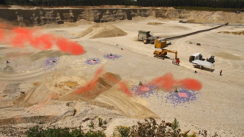
B. Swarm Navigation in a Gas Exploration Mission
As another milestone of our swarm navigation system 20
(generation 2.0), we have demonstrated the DPF performing
in real-time in a gas exploration mission at a gravel pit in
2018. The augmented reality (AR) picture in Figure 5 shows
the experimental environment. Three stationary testbeds were 0
0 20 40 60 80
located at the corners of the experimental area as anchors with
known positions. Five mobile testbeds, the rovers, moved au-
tomatically seeking for two emulated sources of gas dispersion Figure 6: Ranging performance versus true link distances.
[32]. The rovers positions were estimated by the DPF in real-
time. The particles are illustrated with blue dots and the point antenna real-time kinematic (RTK) system, which internally
estimates with the red squares. It can be seen that a sub-meter fuses global navigation satellite system (GNSS) and inertial
to meter level position estimation accuracy is achieved. In measurements. Figure 8 shows the estimated DoAs versus the
Figure 6, the ranging performance versus the true distances true DoAs w.r.t. the three anchors. For all three links, the
between all agent pairs are plotted. Accurate range estimates estimated and the true DoAs match well, resulting in an RMSE
can be obtained with our testbeds, except some outliers due of 3◦ ∼ 4◦ .
to multipath propagation.
D. Information Seeking Swarm Control
C. DoA Estimation with MMA The information seeking swarm control is a work-in-
The latest measurement campagin has been conducted in progress building block, which has been verified with simula-
2020 on grass field, see Figure 7. Four rovers and three tions and is not yet integrated in our swarm navigation testbed.
static anchor boxes were deployed. One of the rovers was We demonstrate here a swarm return-to-base application by
equipped with an MMA and USRP N310 in a setup with four simulation. After exploring an area of interest, the swarm
coherent channels, for details please see [29]. For an MMA, intends to return to its mission base. We consider a more
both amplitude and phase carry DoA information. The four challenge case, where only a single low frequency radio source
receiver channels have been properly calibrated beforehand, in is located at the mission base.
order to compensate phase and magnitude differences. During The swarm optimizes its formation to improve the localiza-
the measurement, DoA estimation was performed in real- tion performances of itself and the radio source, in order to
time. The rover was driving for about 10 min, making several navigate itself back. 34 agents are considered in the network.
turns among and around the anchors. A ground-truth reference Positions of agents and the radio source are exploited as the
for the DoA estimation was provided by a commercial two cost functions in (10). Meantime base approaching is set as(a) Step 1 (b) Step 2000
Figure 9: FI seeking swarm control for swarm return-to-base appli-
cation. The formation of the swarm is optimized to improve self- and
source localization.
Figure 7: Collecting measurement data with the rovers in 2020. The
highlighted rover features a multi-mode antenna for DoA estimation.
Figure 10: Scouting mission on Mt. Etna in 2019 and the envisioned
space-analog LOFAR mission in 2021.
and robotic capabilities in a lunar-analogue environment on
Mt. Etna (Sicily, Italy) in 2021 [31]. The demonstration
mission consists of three scenarios that scientifically focus on
geological research and radio astronomy, which are relevant
for future exploration activities. The first two scenarios ex-
Figure 8: Estimated vs true DoA for signals received from three static amine technical and operational aspects of geological in-situ
neighbours. The DoA is estimated with an MMA mounted on a rover, analysis and sample return. The third scenario demonstrates
which is driving for 10 min.
the autonomous installation and maintenance of a LOFAR
with heterogeneous robots, which is illustrated in Figure 10.
another cost function. The swarm formations at the initial LOFAR payload boxes are deployed by the lightweight rover
snapshot and after 2000 snapshots are shown in Figure 9. The and precisely synchronized and localized with our swarm
direction of the radio source is illustrated with the magenta navigation system. Low frequency radio signal transmitted
dashed line. Agents are represented as green dots, except the either from space or by an artificial transmitter is sensed by
two defining the swarm coordinate system, which are shown as this array. As highlighted in red color, the two-way ranging
the blue dots. Magenta ellipses indicate the position MSE of function has been verified with two payload boxes in the
agents inferred by FI. The swarm automatically spreads out scouting mission on Mt. Etna in 2019.
vertically to the direction of the source, which significantly
increases the effective aperture to improve source localization. VII. S UMMARY AND C ONCLUSION
Meantime, agents remain connected with a regular lattice In this paper we have addressed the assembling of a swarm
formation, to perform self-localization. In addition, the two navigation system. We have focused on communication, lo-
blue reference agents are separated, in order to optimize the calization, sensing and control aspects. The proposed swarm
swarm coordinate system. navigation system uses OFDM radio signals for both com-
munication between and localization of the swarm system’s
E. Space-Analog Mission on Mt. Etna agents. The radio channel access has been implemented self-
Within the project Autonomous Robotic Networks to Help organized and distributed among the agents, providing flexi-
Modern Societies (ARCHES) we demonstrate technologies bility in terms of the number of agents and preventing singlepoints of failure. We have introduced DiPNet as an algorithm [14] A. Wedler et al., “From single autonomous robots toward cooperative
which uses a distributed particle filter and estimates the agent’s robotic interactions for future planetary exploration missions,” in Proc.
of the Int. Astronautical Congr., IAC, Bremen, Germany, Oct. 2018.
positions directly from the observation of the OFDM radio [15] T. Andre, K. A. Hummel, A. P. Schoellig, E. Yanmaz, M. Asadpour,
signals, which are exchanged mutually between the agents. C. Bettstetter, P. Grippa, H. Hellwagner, S. Sand, and S. Zhang,
Experimental results for DiPNet show a localization accuracy “Application-driven design of aerial communication networks,” IEEE
Commun. Mag., vol. 52, no. 5, pp. 129–137, May 2014.
below 1 m. With that, DiPNet significantly outperforms a [16] J. Degesys, I. Rose, A. Patel, and R. Nagpal, “DESYNC: Self-
traditional two step approach which consists of mutual ranging Organizing Desynchronization and TDMA on Wireless Sensor Net-
between the agents and subsequent location determination works,” in 6th International Symposium on Information Processing in
Sensor Networks, 2007. IPSN 2007, april 2007, pp. 11 –20.
of the agents using the range estimates between the agents. [17] R. M. Buehrer, H. Wymeersch, and R. M. Vaghefi, “Collaborative sensor
Orientation estimation based on MMAs has shown an RMSE network localization: Algorithms and practical issues,” Proc. IEEE, vol.
of 3◦ ∼ 4◦ . 106, no. 6, pp. 1089–1114, Jun. 2018.
[18] S. Zhang, E. Staudinger, T. Jost, W. Wang, C. Gentner, A. Dammann,
The presented selection of results was obtained using our H. Wymeersch, and P. A. Hoeher, “Distributed direct localization suit-
experimental swarm system platform. Already the current gen- able for dense networks,” IEEE Trans. Aerosp. Electron. Syst., vol. 56,
eration of our platform provides evidence that swarm systems no. 2, pp. 1209–1227, 2020.
[19] H. Wymeersch, J. Lien, and M. Win, “Cooperative localization in
are able to navigate with sufficient accuracy in unknown and wireless networks,” Proc. IEEE, vol. 97, no. 2, pp. 427–450, Feb. 2009.
previously untouched exploration areas like planetary surfaces. [20] A. T. Ihler, J. W. Fisher, R. L. Moses, and A. S. Willsky, “Nonparametric
belief propagation for self-localization of sensor networks,” IEEE J. Sel.
ACKNOWLEDGMENT Areas Commun., vol. 23, no. 4, pp. 809–819, Apr. 2005.
[21] F. Meyer, O. Hlinka, and F. Hlawatsch, “Sigma point belief propagation,”
Part of the presented research has been supported by the IEEE Signal Process. Lett., vol. 21, no. 2, pp. 145–149, Feb. 2014.
Helmholtz Association project ARCHES (contract number [22] J. Lien, U. J. Ferner, W. Srichavengsup, H. Wymeersch, and M. Z. Win,
ZT-0033) and the German Aerospace Center (DLR) project “A comparison of parametric and sample-based message representation
in cooperative localization,” Int. J. of Navigation and Observation, pp.
Swarm-Navigation. The authors would like to thank Thomas 1–10, 2012.
Wiedemann and Stefano Caizzone for their support. [23] F. Meyer, H. Wymeersch, M. Froehle, and F. Hlawatsch, “Distributed
estimation with information-seeking control in agent networks,” IEEE
R EFERENCES J. Sel. Areas Commun., vol. 33, no. 11, pp. 2439–2456, Nov. 2015.
[1] M. Ballerini et al., “Interaction ruling animal collective behavior depends [24] S. Zhang, R. Raulefs, A. Dammann, and S. Sand, “System-level per-
on topological rather than metric distance: Evidence from a field study,” formance analysis for Bayesian cooperative positioning: From global to
Proceedings of the National Academy of Sciences, vol. 105, no. 4, pp. local,” in International Conference on Indoor Positioning and Indoor
1232–1237, 2008. Navigation (IPIN). IEEE, 2013, pp. 1–10.
[2] C. W. Reynolds, “Flocks, herds and schools: A distributed behavioral [25] M. Viberg, “Introduction to array processing,” in Array and Statistical
model,” in Proc. 14th Annu. Conf. Computer Graphics and Interactive Signal Processing, ser. Academic Press Library in Signal Processing,
Techniques, ser. SIGGRAPH ’87. New York, NY, USA: ACM, 1987, A. M. Zoubir, M. Viberg, R. Chellappa, and S. Theodoridis, Eds.
pp. 25–34. Boston: Elsevier, 2014, vol. 3, ch. 11, pp. 463–502.
[3] M. Moussaid, S. Garnier, G. Theraulaz, and D. Helbing, “Collective [26] A. U. Ahmed, M. T. Islam, and M. Ismail, “Estimating DoA from
information processing and pattern formation in swarms, flocks, and radio frequency RSSI measurements using multi-element femtocell
crowds,” Topics in Cognitive Science, vol. 1, no. 3, pp. 469–497, 2009. configuration,” IEEE Sensors Journal, vol. 15, no. 4, pp. 2087–2092,
[4] M. G. Hinchey, R. Sterritt, and C. Rouff, “Swarms and swarm intelli- Apr. 2015.
gence,” IEEE Computer, vol. 40, no. 4, pp. 111–113, Apr. 2007. [27] M. Hartmann, M. Wohler, M. Schühler, L. Weisgerber, J. Thielecke,
[5] S. Li, R. Batra, D. Brown, H.-D. Chang, N. Ranganathan, C. Hoberman, and A. Heuberger, “A dual frequency antenna for RSSI-based DOA
D. Rus, and H. Lipson, “Particle robotics based on statistical mechanics estimation — From theory to prototype,” in Proc. Days Diffraction (DD),
of loosely coupled components,” Nature, vol. 567, pp. 361–365, Mar. Jun. 2016, pp. 182–187.
2019. [28] R. Pöhlmann, S. A. Almasri, S. Zhang, T. Jost, A. Dammann, and P. A.
[6] M. Bernard, K. Kondak, I. Maza, and A. Ollero, “Autonomous trans- Hoeher, “On the potential of multi-mode antennas for direction-of-arrival
portation and deployment with aerial robots for search and rescue estimation,” IEEE Transactions on Antennas and Propagation, vol. 67,
missions,” J. Field Robot., vol. 28, no. 6, pp. 914–931, 2011. no. 5, pp. 3374–3386, May 2019.
[7] M. Dunbabin and L. Marques, “Robots for environmental monitoring: [29] R. Pöhlmann, G. Pedregosa, S. Caizzone, E. Staudinger, and P. A.
Significant advancements and applications,” IEEE Robot. Autom. Mag., Hoeher, “Multi-mode antenna enabled direction-of-arrival estimation for
vol. 19, no. 1, pp. 24–39, Mar. 2012. swarm navigation,” in Proc. 16th Workshop Positioning, Navigation and
[8] A. Seeni, B. Schfer, and G. Hirzinger, “Robot mobility systems for Communications (WPNC), Bremen, Germany, Oct. 2019, pp. 1–6.
planetary surface exploration – state-of-the-art and future outlook: A [30] R. Pöhlmann, S. Zhang, A. Dammann, and P. A. Hoeher, “Fundamental
literature survey,” in Aerospace Technologies Advancements, T. T., Ed. limits for joint relative position and orientation estimation with generic
London: InTech, Jan. 2010, pp. 189–208. antennas,” in Proc. 26th European Signal Processing Conf. (EUSIPCO),
[9] S. Zhang, R. Pöhlmann, T. Wiedemann, A. Dammann, H. Wymmeersch, Rome, Italy, 2018, pp. 697–701.
and P. A. Hoeher, “Self-aware swarm navigation in autonomous explo- [31] M. J. Schuster et al., “The ARCHES space-analogue demonstration
ration missions,” Proc. IEEE, vol. 108, no. 7, pp. 1168–1195, 2020. mission: Towards heterogeneous teams of autonomous robots for col-
[10] A. L. Christensen, R. O’Grady, and M. Dorigo, “From fireflies to fault- laborative scientific sampling in planetary exploration,” IEEE Robotics
tolerant swarms of robots,” IEEE Trans. Evol. Comput., vol. 13, no. 4, and Automation Letters, pp. 1–1, 2020.
pp. 754–766, Aug. 2009. [32] T. Wiedemann, D. Shutin, and A. J. Lilienthal, “Model-based gas source
[11] E. Vassev, R. Sterritt, C. Rouff, and M. Hinchey, “Swarm technology localization strategy for a cooperative multi-robot system—a proba-
at NASA: Building resilient systems,” IEEE IT Prof., vol. 14, no. 2, pp. bilistic approach and experimental validation incorporating physical
36–42, Mar. 2012. knowledge and model uncertainties,” Rob. Auton. Syst., 2019.
[12] N. R. Raz and M. Akbarzadeh-T., “Swarm-fuzzy rule-based tar-
geted nano delivery using bioinspired nanomachines,” IEEE Trans.
Nanobiosci., pp. 1–1, 2019.
[13] M. Schwager, B. J. Julian, M. Angermann, and D. Rus, “Eyes in the sky:
Decentralized control for the deployment of robotic camera networks,”
Proc. IEEE, vol. 99, no. 9, pp. 1541–1561, Sep. 2011.You can also read