ATHENA The AutoCAD application for curtain wall design and façade engineering - CAD-PLAN
←
→
Page content transcription
If your browser does not render page correctly, please read the page content below

ATHENA The AutoCAD application for curtain wall design and façade engineering

There are two key ingredients necessary to design impressive
façades that function well. The first ingredient is a capable designer
with experience and a knack for technically ingenious solutions.
The second is a powerful CAD application that is precisely tailored
to the designer’s requirement and provides the support for pro-
fessional, error free designs that require less work and are delivered
on time.
This is where we call upon our AutoCAD application, ATHENA, the
all-round software solution for design in
• metal and facade construction
• curtain wall and shopfront construction
• glass construction
• industrial construction
• lightweight steel construction.

ATHENA is the leading CAD based design software for curtain wall design and façade engi-
neering on the market—and not without reason. Our software has been subject to consistent
on-going development since 1989 and is used in metal construction companies, design
offices and universities—in ten languages and more than seventy countries.
Matched exactly to our users' requirements, ATHENA is a complete CAD software package,
offering practically everything to simplify the daily design tasks that confront the designer:
• A 2D drawing environment with practical routines and libraries for producing shop drawings
  (elevations, cross-sections and workshop drawings).
• A versatile 3D design section with the possibility of producing parts lists and production
  drawings directly from the 3D design.
• Powerful computational tools for structural analysis and building physics.
• A sheet editing program for sheet design and development.
In addition, ATHENA is independent from specific profile manufacturers’ systems and can
be matched to individual needs.

Four-way versatility!                             Functional Group 2: 3D design                       Functional Group 3: Sheet editing
                                                  The 3D design is used for the free planning         ATHENA now contains a complete sheet
ATHENA contains four functional groups
                                                  of complicated geometries, such as, sloping         editing program for the quicker design of
covering a range of performance for which
                                                  polygon façades, pyramids, glazed roofs             sheets with the associated developments.
you would have to procure four different
                                                  and bays. To achieve this, profiles or profile      Increased productivity during sheet design
programs.
                                                  groups are placed over the axes of a wire           comprises of clearly laid-out dialog boxes
                                                  model. Cut parts can be automatically com-          for the input of basic sheet data and pro-
                                                  puted and the components (e.g. profiles) are        cesses, a 3D viewer for continuous visual
Functional Group 1: 2D design                     output with the cut parts in a parts list or in a   checks and versatile options for the import
2D drawing functions are tuned for the            workshop drawing                                    and export of drawing data.
rapid production of section and elevation
                                                  Dedicated master data can be created, con-
drawings, plan views and production draw-
                                                  taining the profile geometries, material prop-
ings. Numerous little helpers particularly
                                                  erties, design rules or requirements from
promote productivity. For example, routines
                                                  production. Based on this master data, as           Functional Group 4: Engineering
for semi-finished products, membranes,
                                                  well as spatial elements you can design flat        Always on the safe side. ATHENA’s com-
thermal insulation, welded seams or panels
                                                  elements, such as windows and doors.                putational functions for structural analysis
or the very extensive standard parts library
which, apart from the illustration and labeling   The 3D design takes into account profile            and building physics are well-developed
of the parts, also provides information on        groups, cut parts, processes, sheet metal,          tools for the exact determination of, for
approvals and installation hints. Or the tools    glazing and also hardware. It can be dis-           example, centers of gravity and moments,
for the management of materials, layers           played as a 3D view, 2D view and through            thermal resistances or sound insulation di-
and blocks. Particularly, advantageous - all      any sections. The extracts can be output as         mensions. You can conveniently compute
ATHENA objects are intelligent ARX objects        parts lists or as production drawings. Op-          the required moments of inertia or maximum
and can be labeled and edited with a double       tionally, an NC-X generator is available with       deflections. You can also carry out thermal
click!                                            which the NC data for profile-processing            bridge analyses (isothermal calculations).
                                                  centers can be generated.                           In this way thermal bridges can be elimi-
A special advantage is that all ATHENA                                                                nated during the design stage.
objects are intelligent ARX objects and can       Interfaces to LogiKal (Orgadata) and ERPlus
be edited with a double click!                    (T.A. Project) are also provided.

  Ideal for international design: ATHENA labels all the customer
  objects fully automatically and is able to translate a drawing into
  each of the twelve languages currently contained in ATHENA on
  the press of a key.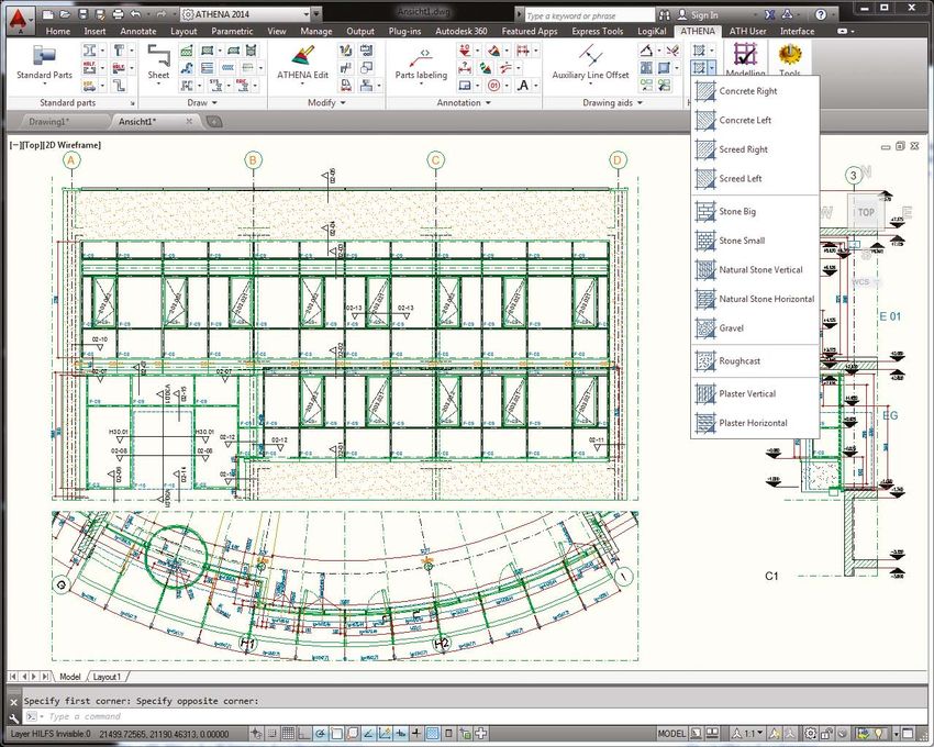
2D Design
    Classical two-dimensional construction takes up a particularly large part of the
    designer‘s workday routine—drawing views, generating cross-sections, drawing
    up detailed drawings, producing manufacturing documentation. The situation is
    also unlikely to change in the short term. The optimization of the work procedure
    with a special software solution leads to increased productivity and a higher-quality
    finished product. This is a big advantage for the designer who is no longer impeded
    by the limitations of the working tools and has a powerful assistant at his side to
    relieve much of the work.
    ATHENA has proven its capabilities over years and the 2D section especially profits
    from careful maintenance and on-going development.
    Numerous routines simplify the drawing of panels, insulation, membranes, welded
    seams, sheet or glazing cross-sections. Clearly laid-out dialog boxes gather im-
    portant information and with the positioning aids the object is conveniently placed
    in its position in the drawing. ATHENA handles everything else.                         Standard parts/manufactured parts
    Many vast built-in expandable libraries make light work of inserting objects into the   Standard parts are available in the standards DIN, ISO,
    drawing, e.g. profile systems, standard parts or screws and other hardware. Various     EN, GOST (Russian), GB/T (Chinese) and AISC (USA)
    international standards are also provided.                                              The selection of the standard parts or manufactured
    Dimensioning also becomes a pleasure with ATHENA: In addition to the AutoCAD            parts is carried out in the dialog box using illustra-
                                                                                            tions or pick lists. The presentation can be influ-
                                                                                            enced through the type of labeling and the display 1
    dimension functions there are efficient connected dimensions, fully automatic object
    dimensions, level and interrupted dimensions which are also implemented by
    viewports in the layouts, and are carried through associatively when geometrical        of the center lines, hidden lines, thread lines and
    changes occur.                                                                          hole center lines. Important: The parts are not “dumb”
                                                                                            blocks, but intelligent “variants”. This facilitates, for
    All ATHENA objects are ARX objects and can therefore be edited with a double            example, the stretching of a screw in steps according
    click. Object labeling is automatically adapted for changes of dimension.               to the standard. Non-standard lengths are also possible.
    The powerful 2D tools of ATHENA increase productivity, save work time and costs         The number of parts is huge and more are regularly
    plus also help the designer to concentrate on the essential aspects of his work.        added. They can be easily handled using convenient
                                                                                            find and filter functions. Standard parts are available in
                                                                                            six different views and as 3D parts. Profiles (e.g. steel
                                                                                            profiles) can be immediately adopted in 3D models.
                                                                                            Now new: Further information, such as for example,
                                                                                            approvals and installation information, is available for
                                                                                            manufactured parts.

                                                                                                           Screwed assembled joint
                                                                                                           ATHENA has a program for generating
                                                                                                           screwed assembled joints. Screwed
                                                                                                           joints consisting of a number of ATHENA
                                                                                                           parts (screw, washer, nut, hole) can be
                                                                                                           generated and also edited. Frequently
                                                                                                           used screwed joints can be saved in
                                                                                                           libraries for repeated use. Screwed joints
  Profiled sheet                                                                                           can be inserted into the drawing in 6
  The profiled sheet generator facilitates the                                                             different views and also as 3D objects.
  fast insertion of trapezoidal or corrugated
  sheets from various manufacturers. The sheet
  parameters are defined in a dialog box.

Façade Elevations
ATHENA offers many commands for producing windows, doors and façade
elevations. They can be conveniently generated and given profiles and infills
retrospectively. Section generation is possible, diagrams too.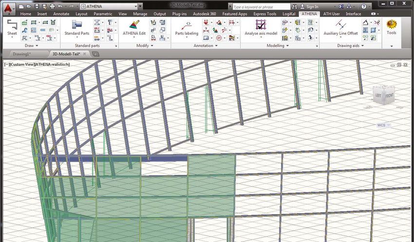
Silicone sealant
To create silicone sealants, click on two       Thermal insulation
lines (or polylines) to create a silicone       Regardless of how the insulation was created, it can          Parts labeling
sealant between them. This can then             be altered using grips or the stretch command, and            All parts are intelligent and can be fully
be pulled to shape using grips.                 made to fit an irregular area. The insulation depth           automatically labeled, also bilingually.
                                                can be specified independent of the thickness of the          Leader texts are adapted automatically
                                                insulation mats. Insulation can be displayed as soft or       when the labeled part is modified. Editing
                                                rigid. The most varied shapes are possible: Straight,         is also child’s play.
                                                curved, wedge-shaped, annular and flat, also with
                                                islands.
                                     2                                                             3                                                    4

                       1                    4                       5

                       2                                                                                      Sheet metal section
                                                                                                              You can create material specific sheet metal
                                                                                                              sections. The limbs can be straight or curved.
                                                                                                              With the sheet development routines the
                                                                                                              cross sections (also of composite panels)
                                                                                                              can be developed material-dependently.
                       3                                                                                      Sheets can also be used fully automatically
                                                                                                              for 3D models.

                                                                                                  6

                                                                                                                                                        5

                                                                                                                                                        6

                                                                Management of filling properties
                                                                The management of any type of filling, e.g., glass, metal panel or stone,
                                                                occurs in a dialog box. The filling properties can be saved in a data
                                                                base and then used in any drawing of the 3D module. Complex infill,
                                                                such as coated or offset glazing, is possible.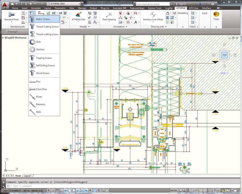
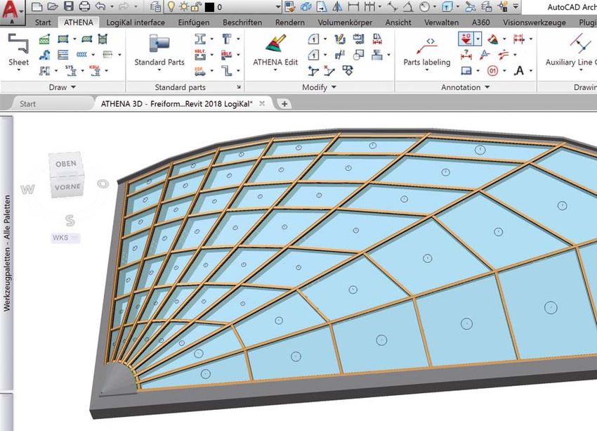
3D Design
  Never before was the three-dimensional design of curtain walls so easy. Sloping polygon façades, pyramids,
  glass roofs, bays and other complicated geometries can be quickly generated without complication.
  As a basis for the production of extensive 3D designs an axis model is used, to the axis lines of which single
  profiles or complete profile groups can be placed. With a simple function an analysis of the axis model can be
  carried out in which also the external side is defined. Thereafter ATHENA recognizes all the angles, field quan-
  tities and alignments within the axis model. Consequently, in conjunction with the application of the designer’s
  own assemblies a high level of automation can be achieved. For example, you can create a mullion and tran-
  som façade with all cut parts at inconceivable speed.
  Just a few working steps are necessary to provide a complete axis model with profile groups incl. joint
  components and hardware, to intercept nodes, to set infills, such as glazing or panels, and to generate
  production drawings or parts lists. There is also the possibility of assigning profile groups and assemblies
  in the form of joint components, drilled holes or other parts or processes which ATHENA can automatically                   Create profile groups
  transfer to bar joints in the 3D design and output them.                                                                    The Bar Assembly Manager
  The ATHENA 3D functionality is orientated for designing a complex three-dimensional facade and preparing it                 of profiles to form an assemb
  for production. Interfaces for transfer to cost calculation and ERP/PPC systems are available. A new feature is             insulator and cover section. W
  an optional NC-X or SAT output for production.                                                                              can be modified or reassigned
                                                                                                                              and mirrored, and the insertio

                                                                     Infills
Glazing
                                                                     Any infills can be generated which can consist           Assemblies
A glazing assembly with cover section, insulator and rubber          of different layers, e.g. panels. These infills are
seals can be composed separately from the basic design.                                                                       Apart from bar-shaped 3D asse
                                                                     assigned to boundary objects, such as transoms
Mullions or transoms can be assigned to this assembly in                                                                      (e.g. glazing or panels), now
                                                                     and posts, by means of freely definable insets.
the 3D design, which is particularly advantageous when                                                                        cesses such as glazing retain
                                                                     Stepped-edge glazing is also possible.
different mullion and transom profiles are used in the façade,                                                                standard parts (screws, nuts
but the glazing is always the same. Also different mounting                                                                   cross-sections and customize
thicknesses can be realized in a façade.                                                                                      semblies can be positioned o
                                                                                                                              grid. The parts of the assemb
                                                                                                                              evaluation (projection) of the
                                                                                                                              the assemblies are ordered ac
                                                                                                                              facilitates a detailed evaluatio

Simplified Display                                                                               Bar diagram
The profiles can either be displayed in full detail, or simplified. There are four dif-          The profile diagrams can be produced after carrying out
ferent display levels. The simplest display (rectangles) reduces the file size to 1/15th,        profiled or mitered). A 2D production drawing of the profile
and the working speed increases correspondingly.                                                 numbers and job data is automatically produced fully dime
facilitates the grouping of a number
bly, e.g. a transom with sealing strips,
Within a profile group, the components         Create parts lists
d. Also, the components can be rotated         Parts lists can be created directly from the 3D drawing from all parts used in the construction. Infill lists
on points can be displaced.                    and bar lists, including raw and cut lengths of the profiles, can be created. Here, tagging is employed, i.e.
                                               even complex 3D parts receive the same label if they are identical and the quantity is incremented. The
                                               lists are created in MS-Excel format.

 emblies (e.g., profiles) and area objects
w local assemblies, i.e. joints and pro-
 ners, can be generated. All ATHENA
s, etc.), holes/elongated holes, sheet
 ed contours can be applied. The as-
on 3D profiles singly or according to a
bly are also positioned during the 2D
 3D profiles. In the structured parts list
ccording to the profile or the infill, which
on in ERP systems.

                                               NC-X or SAT export (optional)
                                               These two optional programs can be used to generate NC data for ATHENA 3D profiles in NC-X format. In
                                               addition to all geometric information such as blanks and machining, the NC data contain order and part
                                               order information and are used for production, e.g. on a profile processing centre. On the other hand, SAT
                                               files can be output from ATHENA 3D profiles, which can also be edited on a profile processing centre using
                                               a postprocessor.

                                               BIM interface
                                               ATHENA includes a BIM (IFC) interface. IFC stands for
                                               “Industry Foundation Classes” and in construction it is the
                                               standard for the description of digital building models, also
                                               known as BIM (Building Information Modeling). Using the
                                               interface it is possible to transfer ATHENA 3D facade models
                                               to so-called BIM programs, such as for example, Autodesk
                                               Revit, and, say, to carry out collision checks with other project
                                               subsections. Along with the 3D objects, job-specific data,
                                               such as item or position numbers, etc. are also transferred.
t the automatic profile cut parts (e.g.
e with lengths, angles, processes, part        Also, objects can be transferred from Revit to ATHENA
ensioned.                                      and then be fitted with profiles, infills, sheets, etc. These can then be returned afterwards.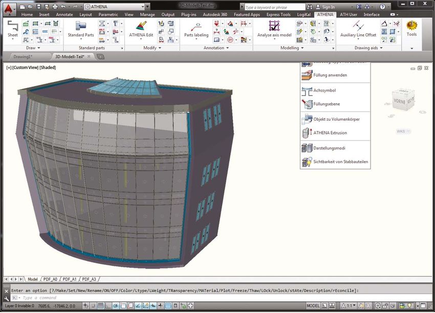
Sheet editing
  ATHENA contains a complete sheet editing program for the quicker
  design of sheets with the associated developments.
  Basic data, for example, sheet thickness and bending radius, form the basis
  of the sheet to be designed. The basic shape is applied to the sheet via
  a dialog box or from a free ATHENA sheet contour. Then, the various
  edges are set and copied in the easiest way to adjacent or opposite sides.
  Many different types of joint are available for the folds. Folds appended
  to a primary surface can be cropped and beveled with an angle.
  Visual checks of the sheet shape via the dynamic 3D viewer ensure
  error-free working.
  Holes or punch-outs can be set in the sheet body at any time. There are
  basic shapes such as circles, rectangles or free contours available for
  this purpose. Customized contours can be generated and saved in a
  library for reuse. The editing processes can be set absolute or associative
  and also rows of punch outs are possible.
  The description of the joint formation, which is important for the develop-
  ment, is easily entered in a dialog box, e.g. the gap dimension and nature
  of the corners of the fold. The computation of the development occurs
  according to the factor tables normally used in metal construction and
  can be saved as required.
  The produced sheet can be inserted into the drawing as a development
  or 3D model. The development can also be saved as a DXF file or
  transferred to MS Excel.

Composite Panels
Apart from normal sheets, composite
panels can be processed, e.g. Alu-                                              The advantages of the sheet editing program are
cobond and Reynobond. Various                                                   summarized below:
types of joint are also available.                                              • Any primary surfaces, folds, processes, separations and
                                                                                  types of joint.
                                                                                • Sheet generation by accepting a 2D cross-section or
                                                                                  directions in a dialog box.
                                                                                • Continuous visual checks via the 3D viewer with zoom/pan
                                                                                  functions.
                                                                                • Development computation via factor tables as is used in
                                                                                  metal construction.
                                                                                • Sheets are managed in libraries (order, partial order, etc.).
                                                                                • Development produced automatically in DXF format for
                                                                                  NC machine control.
                                                                                • Fully compatible to ATHENA 3D.
                                                                                • No procurement of additional “sheet-development
                                                                                  software” is required unless the processing involves
                                                                                  extremely complex metal sheets.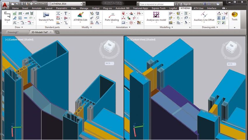
Placement plan for profiled sheets This new tool enables the fully automatic placement of profiled sheet-metal panels within any outlines, e.g. of walls or roofs, and the detailed output. A sheet placement plan with labeling is generated from the specification of the placement orientation (horizontal or vertical), the choice of a profiled sheet from the ATHENA database and an outline via two diagonal corner points. During this process, overlaps, tolerances and sheet thickness values can be determined. With just one step, a parts list, in which identical parts are summarized, can be output from the sheet placement plan. The sheets can be converted to 3D objects with the command “Object to solid body” – for example, to use them in a BIM project. Array Division With the function “Array Division”, any area can be divided into uniform rect angles at any angle with a definable starting point. This function is very versatile; typical applications include wall and ceiling panels, element fa- çades, shaped sheet metal façades, raised floor panels and many more. The output could be a position plan, parts lists or individual part drawings. Stair The „Stair“ module facilitates the design of a stairway and the subse- quent output of the single parts. The output can be provided both in 2D and in 3D and comprises the plan, pitch line, stringers and steps. No further stair software is needed for the design of stairs!
Engineering

Centre of Gravity and moments
This command calculates the center of gravity, moments
of force, centroid axes, radius of inertia, cross-section         Thermal resistance
information such as area, external outline and the weight
of one or more profiles. The center of gravity is marked          Establishment of thermal resistance values of chosen assemblies. The assemblies
and automatically dimensioned. This is ideal for the itera-       can be made of several layers (materials), which can be chosen from a freely
tive process of creating custom project-specific profiles.        extendable library.

                                                                                 Load-case structural analysis
                                                                                 With this static program, load case calculations of bars can be
                                                                                 performed by selecting the high degree of freedom conditions.
                                                                                 The requirements and/or conditions are defined in a dialogue
                                                                                 box. The results can be inserted as a report in the drawing. The
                                                                                 functions are as follows:
                                                                                 • Any number of supports
                                                                                 • Different types of bearing
                                                                                 • Any combination of loads (point and linear loads)
                                                                                 • Differentiation of usable load and permanent load
                                                                                 • Check of the entered values for requirements and reliability.
                                                                                               • Inclusion of safety factors (also freely definable)
                                                                                               • Indication of whether requirement criteria are
                                                                                                 satisfied
                                                                                               • Percentage figure for load factor
                                                                                               • Computation of the buckling stress and buckling
                                                                                                 force
                                                                                                                          • Report: Computation
                                                                                                                            results as table or graphs
                                                                                                                            (e.g. max. deflection, max.
                                                                                                                            stress in the cross section,
                                                                                                                            reaction forces, etc.)

                                                                                                                      Panel / solid thickness
                                                              Ucw – Mean thermal transmission                         calculation
                                                              coefficient                                             Thickness calculation for a panel
                                                              With this command the mean thermal transmis-            or solid body under a defined
Rw – Estimated sound insulation factor
                                                              sion coefficient of a window or a facade can be         loading case. The Bach plate
With this routine the sound insulation factor can be                                                                  formula is used as a basis for
roughly determined for a construction. A results              calculated. A results table can be optionally
                                                              inserted into the drawing.                              the computation.
table can be optionally inserted into the drawing.
Interfaces
Revit App for BIM (optional)
The Revit app “Family/DWG Exporter Importer” was developed to facilitate an
easier and faster BIM data interchange between ATHENA and Revit. This
plugin is used when, for example, in the Revit architect’s plan, the window/
façade elements are already available as “dummies” (rectangular frames).
They are then transferred to ATHENA in a type-oriented manner, where they
are converted to “real” smart façade elements and then transferred back to
Revit according to their type. Here, types are exchanged for the same type.
The “transformed” elements are evaluated in ATHENA.
IFC interfaces (BIM) App download at https://apps.autodesk.com (Search: athena).
Using the proprietary IFC interface, it is possible to trans-
fer ATHENA 3D models (glass roofs, façades, elements,
etc.) in the desired display quality (LOD) incl. all relevant Interface to ERPlus
information to a BIM-capable application, e.g. Revit or ATHENA has an interface to ERPlus with the following functionality:
Navisworks. Non-graphical parts can also be transferred.
• ATHENA standard parts (e.g. standardised parts) can be synchronized with
ATHENA is thus ideally suited for the BIM process.
ERPlus and queried (e.g. for stock availability).
• From a 3D model constructed with ATHENA, the parts (bars, fillings, small
parts) can be transferred to ERPlus.
Element interface to LogiKal and
ERPlus (plane elements)
ATHENA users now have a tridirec-
tional interface available with which
ATHENA, LogiKal and ERPlus can be
linked in real time. The special feature
here is that all three products access
the same data version. A change in a
façade element in one of the programs
leads to an automatic update in the
other two programs, irrespective of
whether it is a change of profile, fields
(e.g. Turn/Tilt to Turn), geometry or
quantities. This saves an enormous
amount of time and sources of error
are eliminated.
LogiKal construction interface
(3D models)
Using LogiKal frame master data,
complex and smart 3D models can be
created in ATHENA. After completion,
it is possible to transfer them to LogiKal
and to evaluate them there.
Optionally, the 3D models can be sup-
plemented in ATHENA, for example
the substructure, wall connections,
sheets, etc., and then transferred via
the IFC interface to a “BIM application”
such as Revit or Navisworks.ATHENA - the solution for curtain wall design and façade engineering.
• Independent of profile system System requirements
• Easy to learn AutoCAD under Windows
• With a high general validity
Please find the current requirements online:
• For engineering design, i.e. not only drawing, but also arithmetic (statics, isotherms, etc.) www.cad-plan.com/systemrequirements
and modelling (3D)
Hardware:
• Excellent list of references! ATHENA requires the same hardware configuration
• Leads the market for design programs for metal construction under AutoCAD, therefore a as AutoCAD.
sound investment. AutoCAD, Revit, Navisworks – registered trade marks of Autodesk Inc.
• Independent of language. A change of language is possible even during the design. The Windows, Excel – registered trade marks of Microsoft Inc.
LogiKal – registered trade mark of ORGADATA AG
following languages are available: ERPlus – registered trade mark of T.A.Project GmbH
- German - Dutch - Russian
- English - Spanish - Chinese
- French - Czech
- Italian - Polish
More information at www.cad-plan.com
CAD-PLAN sales network worldwide:
Czechia, Slovakia: CAD-PLAN Czechia
Germany: CAD-PLAN Slovenia, Albania, Bosnia and Herzegovina, Croatia,
Macedonia, Montenegro, Serbia: DevASI Projektiranje
Netherlands, Belgium, Luxembourg: CAD-PLAN Benelux
CAD-PLAN Poland
Switzerland, France: ACOSOFT
Lithuania, Latvia: AGA-CAD
Hungary: HungaroCAD Informatics
Romania: Window & Facade Technology
CIS: CAD-PLAN Russia
CAD-PLAN China
USA, Canada: CAD-PLAN Orgadata Middle East
Spain, Portugal: MEGA Ingenieras Orgadata India
Orgadata Turkey
Bulgaria: STUDIO CAD
Austria: Grabmayer & Sommer
CAD-PLAN Italy
Malaysia: IAN Metall Engineering
South Africa: Orgadata Middle East
CAD-PLAN GmbH
Hanauer Landstrasse 174
60314 Frankfurt
Germany
Tel. +49-69-800 818-0
info@cad-plan.com
www.cad-plan.comYou can also read