Efficient Symmetry-Based Decomposition for Meshing Quasi-Axisymmetric Assemblies - CAD Journal
←
→
Page content transcription
If your browser does not render page correctly, please read the page content below
478

Efficient Symmetry-Based Decomposition for Meshing Quasi-Axisymmetric
 Assemblies

 Christopher M. Tierney1 , Flavien Boussuge2 , Trevor T. Robinson3 , Declan C. Nolan4 ,
 Cecil G. Armstrong5 and Alexander E. Sansom6

 1 Queens University Belfast, christopher.tierney@qub.ac.uk
 2 Queens University Belfast, f.boussuge@qub.ac.uk
 3 Queens University Belfast, t.robinson@qub.ac.uk
 4 Queens University Belfast, d.nolan@qub.ac.uk
 5 Queens University Belfast, c.armstrong@qub.ac.uk
 6 Rolls-Royce Plc, Alexander.Sansom@rolls-royce.com

 Corresponding author: Christopher M. Tierney, christopher.tierney@qub.ac.uk

 ABSTRACT

 This paper describes a decomposition strategy for hex meshing CAD assembly
 models consisting of quasi-axisymmetric components. A symmetry-based
 decomposition technique is used to isolate portions of model boundaries based upon
 their cyclic symmetry attributes. The calculation of assembly interfaces enables
 symmetry attributes to be passed between adjacent components with the overall
 ambition of achieving a decomposition suitable for conformal hex mesh generation
 of assemblies with quasi-axisymmetric components. The decomposition facilitates a
 multi-sweep approach to hex meshing where axisymmetric and transition portions of
 the boundary are sweepable in the circumferential and radial directions respectively.
 The symmetry-based decomposition is reduced to its equivalent meshable
 representation where axisymmetric regions are represented by their 2D profile,
 reflective symmetry is exploited for transition regions and cyclic symmetric regions
 are defined by a master cyclic segment and a series of transformations. This
 equivalent meshable representation massively reduces the meshing burden for hex
 mesh generation.

 Keywords: Cyclic symmetry, axisymmetric idealization, 3D segmentation, non-
 manifold modelling, CAD assembly, geometric reasoning, hex meshing, simulation
 intent.
 DOI: https://doi.org/10.14733/cadaps.2019.478-495

 Computer-Aided Design & Applications, 16(3), 2019, 478-495
 © 2019 CAD Solutions, LLC, http://www.cad-journal.net

479

1 INTRODUCTION
Significant advances in computational hardware and engineering analysis tools have seen a dramatic
increase in the size and complexity of the models and physics being analyzed. However, resources
are still stretched to their limits when dealing with large CAD assembly models (e.g. whole-engine
aero models consisting of thousands of components) and more advanced analyses (e.g. non-linear
fan blade-off analyses). In many analyses symmetry properties of components, which include
geometry, loading, boundary conditions and material properties, are often exploited by the analyst
to reduce simulation run-time by reducing the numbers of degrees of freedom (DOF) in an idealized
analysis model. For example, it is commonplace for axial, reflective, cyclic and repetitive symmetry
to be exploited for analysis model reduction, provided both geometry and loading exhibit the
specified symmetry properties, e.g. a standard axisymmetric analysis model assumes geometry,
loads and boundary conditions do not vary in the circumferential direction.
 Whilst symmetry idealization of CAD components is a well-established pre-processing tool for
analysis model generation, it has not been fully exploited in automatic mesh generation workflows.
Mesh generation can often be a major bottleneck in analysis processes, especially for the creation
of hexahedral (hex) meshes [16]. In the absence of automatic hex meshing algorithms, the ability
to identify symmetry properties enables the partitioning of a complex model into simpler, repeatable
sub-domains. For example, detecting and isolating cyclic portions of the model boundary enables
one meshed instance to be repeated for all sectors. This reduces the manual meshing burden
required to generate hex meshes as only portions of the model need to be meshed, and the full
mesh can be generated by applying the appropriate symmetry operators used to partition the model.
 Another level of meshing complexity is introduced when dealing with assembly models where
there is often a requirement to have conformal meshes between adjacent components. Therefore,
assembly configurations require any symmetry-based component decompositions to have
compatible interface definitions between adjacent components. In order to achieve this, any
symmetry properties must be transferred between adjacent components. This leads to a
requirement to define how symmetry properties, and perhaps combinations of symmetry properties,
are transferred within assembly configurations. In this work an assembly refers to the Digital Mock-
Up (DMU) which consists of the set of geometric components that are spatially positioned within the
assembly reference frame without having any explicit link between them. The proposed approach
still works on assemblies within which assembly constraints are defined.
 In this work the aim is to detect and utilize the symmetry properties of CAD components, in
combination with assembly interface information, to decompose quasi-axisymmetric assembly
models into axisymmetric and cyclic-symmetric sub-regions and asymmetric residuals. Tracking
assembly interfaces, through symmetry definition changes or after partitioning, enables their
symmetry properties to be updated in order to achieve a conformal mesh. The symmetry-based
decomposition can be used to extract an equivalent meshable representation, which is a significantly
simplified and idealized decomposition. This decomposition is then utilized for hex mesh generation
using a multi-sweeping approach for the different regions in the decomposition.

2 BACKGROUND RESEARCH
Incremental approaches are often employed to help automate and reduce the complexity and manual
effort associated with the hex-meshing of standalone CAD components. These approaches focus on
extracting portions of the geometric model that exhibit certain geometric characteristics which allow
the resulting sub-regions to be meshed with robust hex meshing algorithms, such as sweeping and
mapping. Robinson [20] and Sun [23] both focus on extracting thin-sheet portions of the geometry
(with large lateral dimensions in comparison to the region thickness). Once isolated these regions
can be hex-meshed by sweeping a quad mesh through the thickness. Makem [11] and Sun [22]
extract long-slender regions (with the dimension along the length of the region much greater than
its cross-sectional dimensions). These regions can then be meshed by sweeping a quad mesh of the

 Computer-Aided Design & Applications, 16(3), 2019, 478-495
 © 2019 CAD Solutions, LLC, http://www.cad-journal.net
480

cross-section along the length of the region. These approaches, amongst others [21], [2], [10],
[30], are effectively attempting to generate a sub-division that enables the component to be hex
meshed by multi-sweeping [21]. These methods tend to focus on developing geometric reasoning
algorithms for certain classes of geometry, such as thin-walled components. The work in this paper
focuses on quasi-axisymmetric components and assemblies, where axial and cyclic symmetry
properties are dominant.
 Symmetry detection has been widely studied in the computer graphics community and can be
classified in terms of global or partial symmetry [25] and exact or approximate symmetry [9].
Numerous methods have focused on finding symmetries in mesh models [13] and B-Rep CAD models
[9]. Amongst other applications symmetry detection has been developed for assembly planning [7],
detecting design intent [12] and for restructuring feature trees [6].
 Limited research efforts have been focused on the use of symmetry properties for automatic
mesh generation. Suresh [24] detects global symmetry in 2D cyclic sketches and linearly 3D swept
solids. Tautges [26] uses a lattice structure to exploit symmetry and create meshes for nuclear
reactor geometry assemblies. These approaches are limited to geometries with simple profiles and
obvious sweep directions. This highlights the need for symmetry-based decomposition strategies to
extract partial symmetry properties from within complex 3D geometries that exhibit different
symmetry properties and can include non-symmetric properties. Cao [3] proposed an approach to
use a symmetry-constraint local Delaunay refinement for symmetric 2D or 3D sector meshes. The
proposed approach is limited to fully cyclic components and only focuses on tetrahedral mesh
generation.
 Automatic symmetry detection has often been focused on single components within assemblies
without proper consideration of assembly configurations [9]. Vilmart [28] describes the use of a
knowledge-based approach combined with the symmetry analysis from Li [9] and geometric
interface information to extract repetitive patterns of sets of components within assembly
configurations. This allows components to be grouped into their respective families and would be a
useful a-priori analysis that could instruct the decomposition method in this work as to which
component instances are repeated and only need to be meshed once. Other component instance
meshes could be derived from the master component mesh. In this work the aim is to use calculated
geometric interface information in the assembly to help propagate symmetry properties between
components to facilitate conformal hex meshing of assemblies.
 Non-manifold representations have been used to aid the mesh generation of assemblies, where
non-manifold topological entities, normally faces, between interacting components provide suitable
interfaces for conformal meshing [29]. Qian [18] describes the use of an octree-based approach for
generating unstructured hexahedral meshes for manifold domains and non-manifold assembly
representations. Non-manifold features, such as the interfaces between components in an assembly,
are detected and utilized to modify the base mesh using suitable refinement techniques. However,
a certain degree of element distortion remains at the interfaces. Quadros [19] introduced LayTracks
3D, an approach to generate hex-dominant meshes of solids and assembly models. Quadros
recognizes the increased complexity when meshing assemblies rather than single components.
Assembly imprints are respected and propagated to the medial object (a skeletal representation of
the 3D domain) to help generate a conformal mesh. In this paper interfaces and their symmetry
properties are combined to instruct and guide a decomposition for hex meshing. Modifications to
interface characteristics are tracked and used to enhance the decomposition in order to achieve a
conformal mesh.
 An alternative to using conformal meshing is to use gluing methods (mathematical constraints
between nodes) to join non-conformal meshes [6]. However, gluing approaches can significantly
increase analysis solution times and are also unsuitable for certain analyses. Advantages of the
gluing approach include the ability to reduce mesh propagation in assemblies and the parallelization
of the meshing task. In addition, non-conformal meshes can exist between adjacent components,
including facilitating the desired presence of gaps and overlaps. Clark [3] and White [29] also look
at addressing assembly gaps and overlaps to obtain a conformal mesh by using tolerant imprinting

 Computer-Aided Design & Applications, 16(3), 2019, 478-495
 © 2019 CAD Solutions, LLC, http://www.cad-journal.net
481

techniques. In this work only coincident interfaces are considered, with tolerant interfaces left for
future research.

3 SYMMETRY PROPERTIES OF COMPONENTS
Symmetrical properties of geometries include axial, cyclic (or rotational), reflective and translational
symmetries, or combinations thereof. Quasi-axisymmetric components and assemblies are defined
as having a major axis about which most of the geometry is revolved, and large portions of the
geometry are axisymmetric. These models can also contain certain non-axisymmetric features.
Therefore, in this paper the focus is on the identification and processing of the axisymmetric and
cyclic symmetric portions of the geometry that are prevalent in quasi-axisymmetric components.
 Symmetry around a central point in 2D, or an axis line in 3D, is referred to as cyclic symmetry
and is denoted by Cn, where n is the number of repetitions in the cyclic pattern. This n-fold cyclic
symmetry property helps describe a set of rotation transformations where the angle or rotation
is defined by α=2πi/n where n≥2 and ∈ [1, − 1]. Axisymmetric properties are considered a special
case of cyclic symmetry where n = ∞ and axis-symmetry is denoted by C∞.

 (a) C5 (b) (c) (d) (e) 5

Figure 1: Global symmetry-based decomposition: (a) B-Rep CAD model exhibiting C5 cyclic
symmetry, (b) cyclic sector, (c) sector decomposed into sweepable bodies for multi-sweeping with
arrows representing sweep direction for each sub-region, (d) sector mesh, (e) fully patterned mesh.

 Global symmetry properties of a component describe a transformation that maps the entire
object to itself. Axisymmetric and fully cyclic components exhibit global symmetry around a global
axis of rotation that passes through the component centroid. A component can have multiple
reflective symmetry properties through multiple global reflective planes that must pass through its
centroid. Partial symmetries refer to multiple combinations of symmetric and non-symmetric
properties existing in a single component. These symmetries are represented through the
decomposition of a component into sub-regions in order to isolate the distinct symmetry definitions.
Each distinct partial symmetry transformation is around a global axis or plane of the original
component. Fig. 1 illustrates an example exhibiting global cyclic symmetry, C 5 (i.e. there are five
instances). Once the cyclic sector has been extracted, further manual decomposition is carried out
to facilitate a multi-sweep meshing approach to generate the sector mesh. Cyclic, reflection and
translation symmetry transformations are Euclidean maps as original lengths and angles remain
invariant under transformation. They can be applied to the meshes generated on components
exhibiting these symmetry characteristics. This enables the full component mesh in Fig. 1 (e) to be
generated using the 5 transformations applied to the cyclic sector mesh shown in Fig. 1 (d).

 Computer-Aided Design & Applications, 16(3), 2019, 478-495
 © 2019 CAD Solutions, LLC, http://www.cad-journal.net
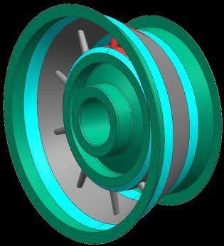
482

 (a) C5 & C∞ (b) (c) C∞ (d) 5 (e) C∞ and 5

Figure 2: Partial symmetry-based decomposition using Fig. 1 (a) as input model: (a) Isolation of
symmetry regions, axisymmetric (C∞) in green, cyclic (C5) in red, (b) equivalent meshable
representation, (c) axisymmetric mesh generation, (d) cyclic mesh generation, (e) full component
mesh.

 Whilst global symmetry can be exploited for simplifying FEA models, it is often desirable to
extract local or partial symmetry properties to aid with hex mesh generation, especially for complex
CAD models where global symmetry often doesn’t exist. Local symmetries are defined using local
axes and planes within a model. In this work we limit the detection to global and partial symmetries
around a global axis of rotation (the axis of rotation is user-specified). Local symmetry detection will
be a subject of future work. Fig. 2 shows decomposition and meshing of the component in Fig. 1
using the process described in [1] to extract the partial symmetry properties and in-effect generating
similar decompositions as required for the multi-sweep in Fig. 1 (c). This decomposition isolates
axisymmetric and cyclic symmetric regions in the component automatically, Fig. 2 (a), and generates
an equivalent meshable representation suitable for hex meshing, Fig. 2 (b), where axisymmetric
regions are represented by their 2D axisymmetric profile, Fig. 2 (c). This equivalent meshable
representation consists of the unique primitives, alongside their associated transformation matrices,
required to generate the full component mesh, Fig. 2 (e).

4 SYMMETRY-BASED DECOMPOSITION FOR HEX MESHING
Previous work [1] by the same authors describes a symmetry detection and decomposition approach
for B-Rep CAD models, depicted in Fig. 3. The main hypothesis is to classify faces as axisymmetric,
cyclic symmetric, pseudo-axisymmetric and non-axisymmetric and use these properties to
decompose the original model into meshable subsets, including axisymmetric and repeatable cyclic
regions. In this work the global symmetry axis is supplied as input by the user. Axisymmetric and
pseudo-axisymmetric faces are first identified. Axisymmetric faces have axisymmetric surface and
boundary definitions, e.g. a cylinder with two peripheral loops. Pseudo-axisymmetric faces have
axisymmetric surface definitions but non-axisymmetric boundaries, e.g. cylindrical faces with inner
loops or non-axisymmetric peripheral edges [1]. Quasi-axisymmetric properties relate to the global
properties of a body, whereas pseudo-axisymmetric properties relate to the local properties of faces.
 Cyclic faces are geometrically and topologically congruent and are repeated around a common
axis of rotation. Cyclic symmetry detection outputs repeated sets of cyclic faces where each face in
the set is congruent with all other repeated entities. These sets of faces are then grouped into cyclic
group patterns, denoted as Gn, with n-fold symmetry consisting of a combination of cyclic faces
defined within that pattern. A single component can consist of m cyclic group patterns. As for face
sets, each cyclic group is congruent to all others in the group set. Any remaining faces are classified
as non-axisymmetric.
 Once faces have been classified into their applicable symmetry group, symmetric portions of the
boundary are isolated as described in [1]. Fig. 3 (b) shows that for the assembly in Fig. 3 (a) which
consists of two components shown in grey and purple, the outer casing is identified as axisymmetric
since it is bounded by all axisymmetric faces. Boundary information of axisymmetric faces and

 Computer-Aided Design & Applications, 16(3), 2019, 478-495
 © 2019 CAD Solutions, LLC, http://www.cad-journal.net
483

suitable projections from pseudo-axisymmetric faces are used to isolate axisymmetric regions. After
isolating all of the axisymmetric portions of the model boundary, Fig. 3 (d) green subsets, cyclic
portions of the boundary are isolated, Fig. 3 (c) red. Prior to decomposition all faces in the cyclic
boundary portion must be cyclic, axisymmetric or pseudo-axisymmetric. After decomposition all
faces become cyclic with attached transformations to define any repeated definitions. The limitation
with the decomposition in Fig. 3 and the work in [1] is that there is no consideration of the assembly
configuration and relationships during the decomposition. This yields an independent decomposition
for each component in the assembly. Therefore, mesh conformity at component interfaces is not
assured.

 (a) (b) C∞ (c) C10 (d) C∞ and C10

Figure 3: Symmetry-based decomposition: (a) CAD assembly, (b) outer casing identified as
axisymmetric (green), (c) identification of cyclic faces and groups (red faces are the master group
and grey the repeated), (d) decomposition of hub into axisymmetric (green), cyclic (red is cyclic and
grey is repeated).

4.1 Interface guided decomposition
Whilst a valid hex mesh can be generated for each of the sub-domains in the decomposition shown
in Fig. 3 (b) an (c), each cell will be meshed without considering its adjacent cells and so connection
elements are required to couple the incompatible meshes of the inner and outer structures. In order
to achieve a fully contiguous hex mesh the interfaces between components need to be identified. To
achieve this Fig. 4 shows the workflow for the overall assembly decomposition approach.

Compatible interface definitions require the imprinting of adjacent component boundaries on one
another. Non-manifold Boolean union operations are used to combine components into a single non-
manifold assembly with multiple connected sub-regions from which the desired non-manifold
interfaces are extracted, Fig. 5 (a). Interface definitions between components are identified in a
standalone non-manifold application developed using the Parasolid Geometric Modelling Kernel [17].
The interface definitions are calculated on a tagged Parasolid assembly file automatically exported
from within Siemens NX [15] and then transferred back within the manifold CAD environment of
Siemens NX which is the tool used for the symmetry detection, decomposition and meshing. This is
achieved by using the appropriate non-manifold boundary information, extracted from the Parasolid
tool, to imprint the equivalent manifold faces in Siemens NX, thus creating exact matching faces
either side of the interface, Fig. 5 (b), and a fully connected assembly representation. Since the non-
manifold interfaces are propagated to the manifold assembly in NX, the Parasolid model can be
discarded once the information has been extracted. These interface definitions are defined after the
initial classification of component faces into their respective symmetry groups.
 After the imprinting operation has been carried out, the simulation attributes of the assembly
interfaces, in this case their symmetry properties, are automatically propagated between
components. This approach is different from the work in [28] where interfaces and component

 Computer-Aided Design & Applications, 16(3), 2019, 478-495
 © 2019 CAD Solutions, LLC, http://www.cad-journal.net
484

symmetries are used to form relationships between collections of components to help identify sub-
assembly symmetries. Keskin et al. [8] describe a novel contact meshing approach whereby the hex
meshing process is simplified by allowing mismatching meshes at ‘glued’ interfaces. This enabled
the generation of all-hex meshes with better quality and a lower total element count but with the
drawback of stress and displacement error in the contact regions. Here the symmetry properties are
transferred from one component to another to help generate a fully compatible and connected hex
mesh at the interfaces. The main assembly interface types that have been considered are based on
the symmetry attributes (axisymmetric, pseudo-axisymmetric, and cyclic) of the faces and are
classified based on the interaction of these properties. How these interfaces are treated dictates the
downstream meshing recipe and the equivalent meshable representation that is created, Section
4.3.

 Figure 4: Workflow of assembly decomposition approach.

 Computer-Aided Design & Applications, 16(3), 2019, 478-495
 © 2019 CAD Solutions, LLC, http://www.cad-journal.net
485 4.1.1 Axisymmetric-axisymmetric interfaces For contiguous meshing purposes interfaces between axisymmetric bodies can be treated in one of two ways. Either the axisymmetric bodies on both sides of the interface can be merged, or the same mesh density can be assigned to all axisymmetric edges in adjacent bodies. This is all that is required to generate a compatible mesh between axisymmetric regions. However, to generate this mesh, matching axisymmetric faces must be generated either side of the interface. Axisymmetric- axisymmetric interfaces can only interact in three different ways: Boundaries of the axisymmetric faces are coincident and therefore the axisymmetric faces are exact matches. Axisymmetric faces overlap, i.e. none of boundaries of the axisymmetric faces are coincident. This means three new axisymmetric faces will be generated with one in common to both axisymmetric bodies, and one unique to each component One axisymmetric face is engulfed by the other. The engulfed face will be common between both bodies and either one or two new axisymmetric faces will be generated depending whether one of the boundary edges is coincident. From the possible axisymmetric interactions listed above it is obvious that only axisymmetric faces can be generated from the interaction between two axisymmetric faces. (a) (b) (c) (d) Figure 5: Interface guided decomposition: (a) assembly interfaces, (b) imprinted interfaces, (c) new decomposition of outer casing, (d) new symmetry properties of outer casing. 4.1.2 Axisymmetric-cyclic interfaces For axisymmetric-cyclic interface types the axisymmetric faces will always inherit the properties of their adjacent cyclic faces from another component. As the axisymmetric and cyclic faces share the same axis of rotation they can only interact in two ways: The cyclic faces are engulfed by the axisymmetric face. The cyclic faces intersect the axisymmetric boundary. From either scenario above, the axisymmetric face is partitioned into a pseudo-axisymmetric face (bounded by the outer boundary of the cyclic faces and the original axisymmetric edges) and a number of cyclic faces. The number of partitioned cyclic faces is equal to the number of loops in a cyclic face (outer and inner loops) multiplied by the cyclic pattern Cn. The cyclic boundaries are then used to decompose the axisymmetric face. Fig. 5 (b) shows the imprinted faces on the outer casing which inherit the C10 cyclic symmetry properties of their adjacent cyclic faces. Since there are two loops in each cyclic face (one outer loop and one inner loop) the number of subset cyclic faces is 20 as the cyclic pattern is C10. Half of these faces are one-one maps with the original cyclic faces themselves, the other half are new cyclic faces generated from the cyclic inner loops. As a result the cyclic groups and face classifications specified are automatically updated after the imprinting operation. Computer-Aided Design & Applications, 16(3), 2019, 478-495 © 2019 CAD Solutions, LLC, http://www.cad-journal.net
486 Using the methodology from [1] the outer casing is then decomposed into the axisymmetric and cyclic regions as shown in Fig. 5 (c). Pseudo-axisymmetric-cyclic interfaces are treated in the same manner as axisymmetric-cyclic interfaces, provided there is no interaction between the cyclic faces and the non-axisymmetric entities bounding the pseudo-axisymmetric face. 4.1.3 Axisymmetric-pseudo-axisymmetric interface A number of different configurations can exist between interacting axisymmetric and pseudo- axisymmetric faces. These configurations depend on the symmetry classification of the edges bounding the pseudo-axisymmetric face and also the nature of the interaction. Fig. 6 depicts some axisymmetric-pseudo-axisymmetric interface interactions and shows how the symmetry properties of the interface can differ from that of the interacting face where: Fig. 6 (a) shows how the pseudo-axisymmetric boundary intersects the axisymmetric faces generating an exact imprint of the original pseudo-axisymmetric face (grey) Fig. 6 (b) and a series of cyclic faces (red). Thus, cyclic faces (red) are generated where cyclic boundary edges of a pseudo-axisymmetric face isolate a subset of an axisymmetric face. Another possible scenario is illustrated in Fig. 6 (c) where the pseudo-axisymmetric interface is engulfed by the axisymmetric face. This results in the generation of two pseudo- axisymmetric faces. Once boundaries of an axisymmetric face are used to partition a pseudo-axisymmetric face the resulting imprinted faces can be either cyclic, axisymmetric or pseudo-axisymmetric depending on the type of interaction and the symmetry properties of the edges bounding the pseudo-axisymmetric face, Fig. 6 (e-h). The important point is that not only do the symmetry properties of the face itself dictate the interface type, but also the symmetry properties of the edges bounding those faces, especially the edges bounding pseudo-axisymmetric faces. Any non-axisymmetric portions of the pseudo-axisymmetric face will be reflected in the adjacent component and subsequently isolated as a non-axisymmetric volume. Likewise, any inner loop in a pseudo-axisymmetric interface will generate a new face on the opposing face which will inherit the symmetry properties of the inner edges. (a) (b) (c) (d) (e) (f) (g) (h) Figure 6: Axisymmetric-pseudo-axisymmetric interactions: (a) two component assembly with pseudo-axisymmetric (left) axisymmetric (right) interface, (b) imprinted interfaces with cyclic (red) and pseudo-axisymmetric (grey) of (a), (c) pseudo-asymmetric interface reduced, (d) imprinted Computer-Aided Design & Applications, 16(3), 2019, 478-495 © 2019 CAD Solutions, LLC, http://www.cad-journal.net
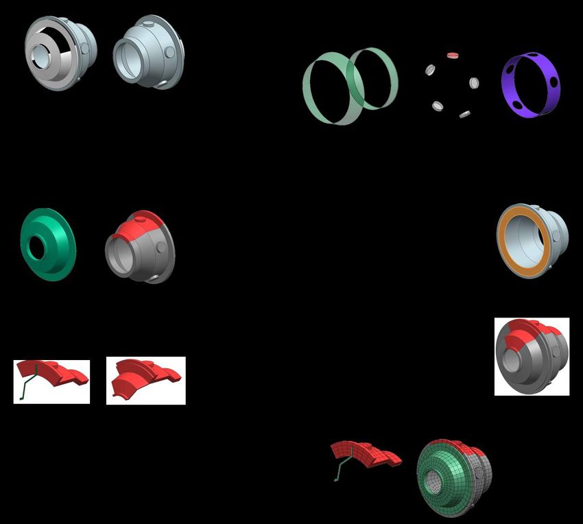
487

interface of (c), (e) pseudo-axisymmetric interface increased, (f) imprinted interface of (e), (g)
axisymmetric interface reduced, (h) imprinted interface of (g).

4.1.4 Cyclic-cyclic interfaces
Cyclic-cyclic interfaces will generally only occur in assemblies when cyclic faces from interacting
components have the same, or similar, cyclic patterns. In addition, the surface definitions of
interacting components will be compatible but they may have different face topologies. Variants in
cyclic patterns between assembly interfaces are most likely to occur after the decomposition where
cyclic patterns from within components propagate to the interface region. This scenario is presented
in the next section.

4.2 Tracking assembly interfaces
The previous sub-section demonstrated how interfaces are treated based upon their symmetry
properties. This section describes how interfaces must be tracked throughout the decomposition to
determine if their symmetry classification and their resulting interaction is altered due to partitioning
at the interface. After the imprinting operations the mapping between matching coincident faces is
stored, i.e. two manifold faces either side of an interface are paired together. This mapping is tracked
after the decomposition phase in order to process interfaces that have been partitioned and whose
symmetry definition has been modified.
 Fig. 7 shows the tracking and updating of assembly interface definitions for two adjacent
components with different cyclic patterns. The original assembly interfaces in Fig. 7 (a) exhibit
axisymmetric symmetry. However, once the decomposition has been performed, Fig. 7 (b), it can
be seen that the original axisymmetric interfaces have been modified to become two distinct cyclic
symmetric definitions, shown in Fig. 7 (d) and (e). In order to achieve a conformal mesh these
symmetry changes must be propagated between the interface regions. Fig. 7 (f) and (g) show
imprints (highlighted in red) from one interface onto the other. In effect, this imprint operation can
either change or maintain the symmetry definition of these interfaces once again. On one side the
C10 master interface is partitioned into two cyclic symmetric faces, Fig. 7 (g). This means the master
interface maintains its C10 cyclic relationships with its slave interfaces enabling the master mesh
(red) to be repeated for the slave meshes (grey), Fig. 7 (h).
 On the other side of the interface the C4 master interface is partitioned into three different faces,
of which two are cyclic. Based upon the partitioning after the imprinting operation the relationship
between the C4 master and slave interfaces is modified to a C2 pattern, Fig. 7 (i), with a reflective
pattern in the y-axis, Fig. 7 (j). However, in meshing terms, since the two cyclic subset faces in the
C4 master interface is a slave interface in the C10 interface definitions it is possible the cyclic pattern
between C4 master and slave interfaces is maintained and used to generate the patterned mesh,
Fig. 7 (k).

 (a) (b) (c) (d) C∞ converted to C10

 (e) C∞ converted to C4 (f) C10 imprint on (g) C4 imprint on (h)
 C4 C10

 Computer-Aided Design & Applications, 16(3), 2019, 478-495
 © 2019 CAD Solutions, LLC, http://www.cad-journal.net
488

 (i) C4 converted to (j) Reflection in y (k)
 C2

Figure 7: Tracking interfaces after decomposition: (a) two component assembly, (b) decomposition
with different cyclic patterns, (c) front view of interface patterns, (d) modified C 10 interface, (e)
modified C4 interface, (f) C10 imprint on C4, (g) C4 imprint on C10, (h) cyclic mesh for (g), (i) cyclic
pattern modified after imprint, (j) new reflective interface symmetry, (k) cyclic mesh of (f).

4.3 Equivalent meshable representation
Simulation Intent [14] refers to the high-level analysis decisions required to generate fit-for-purpose
analysis models. Different Simulation Intent definitions can be utilized on the same design geometry
to produce the different analysis models that may be required for different applications. Tab. 1
illustrates how different simulation intent definitions are used to create different decompositions
required to generate fit-for-purpose meshes. An initial decomposition is carried out to isolate the
axisymmetric and cyclic regions in the model, first decomposition in case 1 in Tab. 1. This initial
decomposition corresponds to the first simulation intent definition of the analyst where a local fine
mesh is desired for a detailed stress analysis. Depending on the simulation intent new appropriate
decompositions are also produced to satisfy analysis requirements. For example, case 2 in Tab. 1
corresponds to an analysis requirement to reduce the number of DOF in the model for a global
assessment of mechanical behavior.

Once the appropriate decompositions are generated the analysis representation is reduced to its
equivalent meshable representation. The equivalent meshable representation is the minimum
number of cells in the specific assembly decomposition from which the full assembly mesh can be
generated by applying the sweep operations or transformation operators defined during the
decomposition phase. As an enhancement to the work in [1], here the equivalent meshable
representations are automatically derived from the decomposition and the full hex meshes are
automatically generated for the different Simulation Intent definitions and are shown in Tab. 1. It is
also demonstrated how different equivalent meshable representations are generated from the same
Simulation Intent definition but can generate the same resulting mesh, e.g. the equivalent meshable
representations generated for the case 1 decomposition. Thus, two different equivalent meshable
representations can be automatically generated to define the same fine mesh. The only difference
being in how the axisymmetric regions are treated.

 Computer-Aided Design & Applications, 16(3), 2019, 478-495
 © 2019 CAD Solutions, LLC, http://www.cad-journal.net
489

 Decomposition Equivalent meshable Equivalent mesh Full conformal
 representation assembly mesh

 Case 1

 Case 2

Table 1: Different decompositions and equivalent mesh representations based on simulation intent.

As the first decomposition (case 1 in Tab. 1) is produced in order to yield a fine mesh the small
element size from the cyclic regions is propagated through adjacent axisymmetric regions. This is
achieved using either of the two following equivalent meshable representations.
 The first equivalent meshable representation that can be utilized to achieve this fine mesh is to
propagate the cyclic partitions into the axisymmetric regions. This means that the axisymmetric cells
in the decomposition are converted to C10 cyclic cells, which makes them sweepable in the
circumferential direction. The mesh density is propagated across the cyclic-axisymmetric interface
and the resulting swept mesh is repeated using the cyclic transformation 10
 for all the cyclic subsets

in the decomposition.
 The second equivalent meshable representation idealizes the axisymmetric regions to their
equivalent 2D axisymmetric profile. The 2D idealized representations are then quad meshed and

 Computer-Aided Design & Applications, 16(3), 2019, 478-495
 © 2019 CAD Solutions, LLC, http://www.cad-journal.net
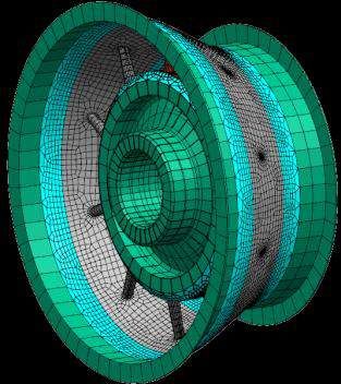
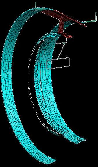
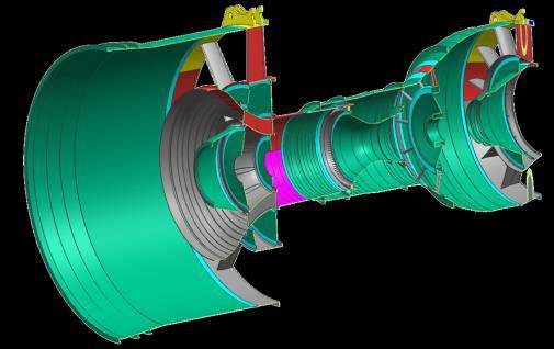
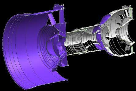
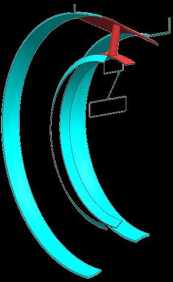
490

revolved to generate 10 × hex elements around the circumference, where N is the number of
nodes on the cyclic-axisymmetric interface. For both options any cyclic periodic faces (the cyclic
partitioning faces) are constrained to have compatible division numbers on equivalent cyclic periodic
edges, thus enabling fully contiguous hex meshes to be generated.
 As the second decomposition (case 2 Tab. 1) is defined for an analysis where there is a
requirement to reduce the number of DOF in the hex mesh it is desirable to transition between
smaller mesh densities in the cyclic regions, where typically detail exists, to larger mesh densities
in adjacent axisymmetric regions. To achieve this the axisymmetric regions are decomposed further,
with an axisymmetric partition, to create transition regions at the axisymmetric-cyclic interfaces,
case 2 Tab. 1 blue regions. In transition regions the mesh is swept through the thickness of the
region. This is in contrast to axisymmetric regions that are swept along the circumferential direction.
Since the transition regions originate from an axisymmetric region they contain C∞ reflective planes.
Therefore, only half of the transition regions need to be represented in the equivalent meshable
representation. A reflection transformation is used to generate the remainder of the mesh.
 The more detailed mesh from case 1 above consists of 38,870 element and 75,480 nodes while
the more efficient mesh generated in case 2 consists of 12,024 elements and 22,728 nodes. This
shows a 70% reduction in the number of elements and nodes between the two models. For case 1
two equivalent representations are used to generate the same final mesh of the assembly. The first
representation is a fully solid decomposition requiring the direct generation of 2,719 hex elements.
This represents only 7% of the overall mesh, with the remaining 93% of elements being cheaply
patterned. The second representation is a mixed-dimensional model consisting of 2D axisymmetric
profiles and solid cyclic regions. This representation requires the direct generation of 823 hex
elements and 110 quad elements, which is only 2.5% of the overall mesh, where the remaining
97.5% of elements generated through either patterning or revolve operations. The decomposition
in case 2 produces a mixed-dimensional model where only 2,168 hex elements and 47 quad elements
are directly generated. This represents 18% of the overall mesh for this decomposition as the
transition zones consume some of the axisymmetric region and the mesh is much coarser than that
of case 1. A benchmark tet meshed model with global 10mm element size (taken as average from
finer hex mesh of case 1) consists of 110,000 elements. Both the fine and efficient hex meshes are
65% and 89% less respectively. It is worth mentioning this gain is with only one element in the
thickness, and as more elements are utilized in the thickness the gains will become more apparent.
 It is worth noting that the aim of this work is to show the automated workflow of the
decomposition strategy, how this is represented as the minimal decomposition and how this can be
meshed and transformed to generate the complete mesh of the assembly. Validation to date has
focused on achieving a fully automated workflow producing a fully connected mesh with no hanging
nodes. Therefore, little effort has focused on mesh quality, such as ensuring there are a suitable
number of elements through the thickness which can differ for different applications. Such
improvements will be the topic of future work where for example multi-block decomposition methods
will be used on the axisymmetric profiles and element division numbers will be automatically
calculated using integer programming routines whose constraints can be informed by the symmetry
properties extracted during the decomposition.

 (a) (b)

 Computer-Aided Design & Applications, 16(3), 2019, 478-495
 © 2019 CAD Solutions, LLC, http://www.cad-journal.net
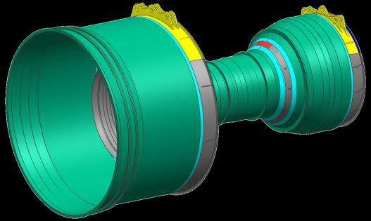
491

 (c) (d)

 (e)

Figure 8: Interface guided decomposition for use-case industrial example: (a) Original assembly, (b)
section view of original assembly, (c) symmetry-based decomposition of assembly, (d) section view
of (c), finally (e) is the equivalent meshable decomposition of (c).

5 RESULTS AND DISCUSSION
Fig. 8 (a) shows the use-case utilized in this research which is a simplified aero-engine model
supplied for academic research as part of the CRESCENDO project [5]. The assembly consists of 5
components with a total of 1112 faces, 2381 edges and 1433 vertices. The described approach has
been implemented using the C# language and .NET framework APIs in Siemens NX [15] and
Parasolid [17]. The automated identification and decomposition, shown in Fig. 8, takes 3 minutes
12s (on 64-Bit Windows machine with a 3.7GHz Intel Zeon E5-1630 CPU with 32GB RAM). This
includes the symmetry-based decomposition, Fig. 8 (c) and (d), and the generation of the equivalent
meshable representation, Fig. 8 (e), which comprises the tracing and creation of the axisymmetric
2D profiles. The equivalent meshable representation resulting from the decomposition reduces the
complexity of the hex meshing problem where: 60% of the original model volume is now represented
as axisymmetric bodies (green); 28% is identified as cyclic (red and grey); 5% as transition regions
(cyan) and 4% is non-axisymmetric (yellow). The remaining 3% is comprised of the sweepable /
long-slender (blue) and block topology regions. Therefore 60% of the original volume has been
reduced to a 2D meshing problem, as the 2D axisymmetric profile are quad meshed and revolved.
Transition, sweepable and block regions can all be easily meshed with existing sweep and mapping
algorithms. This leaves only the cyclic and non-axisymmetric regions to be dealt with. Since the
cyclic region meshes are generated with n repetitions of a master mesh, only 3% of the cyclic subsets
need meshed with the residual 25% being repeated. Of this 3% of master cyclic cells, approximately
half are identifiable as sweepable (using the topological algorithm in [27]). This means with only the

 Computer-Aided Design & Applications, 16(3), 2019, 478-495
 © 2019 CAD Solutions, LLC, http://www.cad-journal.net
492

remaining 1.5% cyclic and 4% non-axisymmetric cells there is merely 5.5% of the original assembly
that needs to be further processed for hex meshing.
 Currently the example in Fig. 8 cannot be automatically meshed due to the further effort required
to mesh the un-sweepable cyclic and non-axisymmetric subset cells. However, the example provided
in Tab. 1 shows the generation of two distinct symmetry-based decompositions from an original
assembly. The different decompositions facilitate the creation of different fit-for-purpose meshes.
The decomposition, generation of equivalent meshable representations, generation of the meshing
recipe and meshing are all automated for the example in Tab. 1, with each automated process taking
493

 is how the interactions between symmetries at the interfaces will be processed and how this will
 constrain the downstream meshing process. For example, for rotating components the
 decomposition strategy will need to be altered to avoid the creation of sliver entities at the interface.
 Another consideration when treating moving interfaces is the possibility of mesh inconsistencies at
 the interface, e.g. mismatching meshes may result when components either side of the interface
 move or mesh penetration may occur, where nodes on one side of the interface penetrate elements
 on the other side. In this work the interface between adjacent components is explicit, meaning once
 common mesh is correctly defined between them by assigning the correct division numbers, these
 issues can be managed at the interface.

 6 CONCLUSIONS
 This paper introduces a symmetry-based decomposition approach for quasi-axisymmetric CAD
 assembly models. Faces in all components are classified based upon their symmetry properties. Next
 interfaces between components are identified and used to propagate symmetry properties between
 adjacent components. Those interfaces completely engulfed by their adjacent face transfer their
 symmetry definition to the adjacent components. Where boundaries of interface regions intersect
 the resulting imprinted faces inherit symmetry from the partitioning edges. Axisymmetric and cyclic
 portions are extracted from each component. Interfaces are re-evaluated to determine if their
 symmetry properties have been modified during the component decomposition. Modified interfaces
 are utilized to generate an enhanced decomposition consisting of compatible interface suitable for
 conformal meshing.
 Different equivalent meshable representations and therefore different fit-for-purpose hex
 meshes are automatically defined depending on the simulation intent specified by the analyst.
 Distinct equivalent meshable representations can be generated from the decomposed geometry,
 both of which adhere to the same Simulation Intent definition and are used to create the same fit-
 for-purpose mesh. Also, different Simulation Intent definitions can be used to create considerably
 different decompositions for the same design geometry. Utilizing the equivalent meshable
 representations with the appropriate transformations significantly reduces the burden required to
 mesh the overall assembly, as can be seen in the use-case where less than 6% of the model wasn’t
 instantly hex meshable using this approach.

 7 ACKNOWLEDGEMENTS
 The authors wish to acknowledge the financial support provided by Innovate UK via the GEMinIDS
 (project 113088), a UK Centre for Aerodynamics project, and also the support provided by the
 European Commission via the MUMPS project (704557), a H2020-MSCA-IF-2015 founding scheme.
 The authors acknowledge Rolls-Royce for granting permission to publish this paper.

 Christopher M. Tierney, http://orcid.org/0000-0003-3341-6902
 Flavien Boussuge, http://orcid.org/0000-0002-1407-898X
 Trevor T. Robinson, http://orcid.org/0000-0002-6595-6308
 Declan C. Nolan, http://orcid.org/0000-0002-9388-6183
 Cecil G. Armstrong, http://orcid.org/0000-0001-8695-5016

REFERENCES
[1] Boussuge, F.; Tierney, C. M.; Robinson, T. T.; Armstrong, C. G.: Symmetry-based decomposition
 for meshing quasi-axisymmetric components, 26TH International Meshing Roundtable, 2017,
 375-387. https://doi.org/10.1016/j.proeng.2017.09.812

 Computer-Aided Design & Applications, 16(3), 2019, 478-495
 © 2019 CAD Solutions, LLC, http://www.cad-journal.net
494

[2] Boussuge, F.; Léon, J.-C.; Hahmann, S.; Fine, L.: Idealized models for FEA derived from
 generative modeling processes based on extrusion primitives, Engineering with Computers,
 31(3), 2015, 513–527, 2015. https://doi.org/10.1007/s00366-014-0382-x
[3] Cao, W.; Li, M.; Gao, S.: Optimal Rotational Symmetry Cell Mesh Construction for FE Analysis
 by Symmetry-constrained Local Delaunay Refinement, Computer-Aided Design and Applications,
 11(3), 2014, 326–334. https://doi.org/10.1080/16864360.2014.863505
[4] Clark, B.; Hanks, B.; Ernst, C.: Conformal assembly meshing with tolerant imprinting.
 Proceedings of 17th International Meshing Roundtable, 2008, 267–280.
 https://doi.org/10.1007/978-3-540-87921-3_16
[5] CRESCENDO, Collaborative and robust engineering using simulation capability enabling next
 design optimization. [Online]. http://www.crescendo-fp7.eu. Accessed 4 February 2018.
[6] Eguzkitzaa, B.; Houzeauxa1, G.; Calmeta, H.; Vázqueza, M.; Sonib, B.; Aliabadib, S. Batesc, A.;
 Doorlyc, D.: A gluing method for non-matching meshes, Computers and Fluids, 110, 2015, 159-
 168. https://doi.org/10.1016/j.compfluid.2014.09.036
[7] Jiang, J.; Chen, Z.; He, K.: A feature-based method of rapidly detecting global exact symmetries
 in CAD models, Computer-Aided Design, 45(8), 2013, 1081–1094.
 https://doi.org/10.1016/j.cad.2013.04.005s
[8] Keskin, A.; Kober, M.; Stelldinger, E.; Kuehhorn, A.; Boehm, H.; Hornig, A.; Hufenbach, W.: On
 the quantification of errors of a pre-processing effort reducing contact meshing approach, 53rd
 AIAA Aerospace Sciences Meeting, AIAA SciTech Forum, 2015. https://doi.org/10.2514/6.2015-
 0408
[9] Li, K.; Foucault, G.; Leon, J.-C.; Trlin, M.: Fast global and partial reflective symmetry analyses
 using boundary surfaces of mechanical components, Computer-Aided Design, 53, 2014, 70-89.
 https://doi.org/10.1016/j.cad.2014.03.005
[10] Lu, Y.; Gadh, R.; Tautges, T.J.: Feature based hex meshing methodology: feature recognition
 and volume decomposition, Computer-Aided Design, 33(3), 2001, 221–232.
 https://doi.org/10.1016/S0010-4485(00)00122-6
[11] Makem, J. E.; Armstrong, C. G.; Robinson, T. T.: Automatic decomposition and efficient semi-
 structured meshing of complex solids, Engineering with Computers, 30(3), 2014, 345-361.
 https://doi.org/10.1007/s00366-012-0302-x
[12] Ming, L.; Langbein, F. C.; Martin, R. R.: Detecting design intent in approximate CAD models
 using symmetry, Computer-Aided Design, 42(3), 2010, 183-201.
 https://doi.org/10.1016/j.cad.2009.10.001
[13] Mitra, N. J.; Guibas, L. J.; Pauly, M.: Partial and approximate symmetry detection for 3D
 geometry, in ACM Transactions on Graphics, 25(3), 2006, 560–568.
 https://doi.org/10.1145/1179352.1141924
[14] Nolan, D. C.; Tierney, C. M.; Armstrong, C. G.; Robinson, T. T.: Defining simulation intent,
 Computer-aided design, 59, 2015, 50-63. http://.doi.org/10.1016/j.cad.2014.08.030
[15] NX, http://www.plm.automation.siemens.com/en_gb/products/nx/, Siemens.
[16] Owen, S. J.; Clark, B. W.; Melander, D. J.; Brewer, M.; Shepherd, J. F.; Merkley, K.; Ernst, C.;
 Morris, R.: An immersive topology environment for meshing, 16th International Meshing
 Roundtable, 2008, 553-577. https://doi.org/10.1007/978-3-540-75103-8_31
[17] Parasolid, http://www.Plm.Automation.Siemens.com/en_gb/products/open/parasolid, Siemens.
[18] Qian, J.; Zhang, Y.: Automatic unstructured all-hexahedral mesh generation from B-Reps for
 non-manifold CAD assemblies, Engineering with Computers, 28(4), 2012, 345-359.
 https://doi.org/10.1007/s00366-011-0232-z
[19] Quadros, W. R.: LayTracks3D: A New Approach to Meshing General Solids using Medial Axis
 Transform, Procedia Engineering, 82, 2014, 72-87.
 https://doi.org/10.1016/j.proeng.2014.10.374
[20] Robinson, T. T.; Armstrong, C. G.; Fairey, R.: Automated mixed dimensional modelling from 2d
 and 3d cad models, Finite Elements in Analysis and Design, 47(2), 2011, 151-165.
 http://doi.org/10.1016/j.finel.2010.08.010

 Computer-Aided Design & Applications, 16(3), 2019, 478-495
 © 2019 CAD Solutions, LLC, http://www.cad-journal.net
495

[21] Scott, M. A.; Benzley, S. E.; Owen, S. J.: Improved many-to-one sweeping. International Journal
 for Numerical Methods in Engineering, 65(3), 2006, 332–348.
 https://doi.org/10.1002/nme.1444
[22] Sun, L.; Tierney, C.; Armstrong, C.; Robinson, T.: An enhanced approach to automatic
 decomposition of thin-walled components for hexahedral-dominant meshing, Engineering with
 Computers, 2017. https://doi.org/10.1007/s00366-017-0550-x
[23] Sun, L.; Tierney, C.; Armstrong, C.; Robinson, T.: Decomposing complex thin-walled CAD
 models for hexahedral-dominant meshing, Computer-Aided Design, 2017.
 https://doi.org/10.1016/j.cad.2017.11.004
[24] Suresh, K.; Sirpotdar, A.: Automated symmetry exploitation in engineering analysis, Engineering
 with Computers, 21(4), 2006, 304-311. https://doi.org/10.1007/s00366-006-0021-2
[25] Tate, S. J.; Jared, G. E. M.: Recognizing symmetry in solid models, Computer-Aided Design,
 35(7), 2003, 673-692. https://doi.org/10.1016/S0010-4485(02)00093-3
[26] Tautges, T. J.; Jain, R.: Creating geometry and mesh models for nuclear reactor core geometries
 using a lattice hierarchy-based approach, Engineering with Computers, 28(4), 2012, 319-329.
 https://doi.org/10.1007/s00366-011-0236-8
[27] Tierney, C. M.; Sun, L.; Robinson, T. T.; Armstrong, C.G.: Using virtual topology operations to
 generate analysis topology, Computer-Aided Design, 85, 2016 154–167.
 https://doi.org/10.1016/j.cad.2016.07.015
[28] Vilmart, H.; Leon, J.-C.; Ulliana, F.: From CAD assemblies toward knowledge-based assemblies
 using an intrinsic knowledge-based assembly model, Computer-Aided Design and Applications,
 2017, 1-18. https://doi.org/10.1080/16864360.2017.1397882
[29] White, D.R.; Saigal, S.; Owen, S. J.: An imprint and merge algorithm incorporating geometric
 tolerances for conformal meshing of misaligned assemblies, International Journal for Numerical
 Methods in Engineering, 59(14), 2004, 1839–1860. https://doi.org/10.1002/nme.937
[30] Wu, H.; Gao, S.: Automatic Swept Volume Decomposition based on Sweep Directions Extraction
 for Hexahedral Meshing, Procedia Engineering, 82, 2014, 136–148.
 https://doi.org/10.1016/j.proeng.2014.10.379

 Computer-Aided Design & Applications, 16(3), 2019, 478-495
 © 2019 CAD Solutions, LLC, http://www.cad-journal.net
You can also read