Visualizing atomic structure and magnetism of 2D magnetic insulators via tunneling through graphene
←
→
Page content transcription
If your browser does not render page correctly, please read the page content below
ARTICLE
                  https://doi.org/10.1038/s41467-020-20376-w                OPEN

                  Visualizing atomic structure and magnetism of 2D
                  magnetic insulators via tunneling through graphene
                  Zhizhan Qiu 1,8, Matthew Holwill 2,8, Thomas Olsen 3,8, Pin Lyu1, Jing Li                                         4,   Hanyan Fang        1,

                  Huimin Yang1, Mikhail Kashchenko2,5, Kostya S. Novoselov2,4,6,7 ✉ & Jiong Lu                                     1,4 ✉
1234567890():,;

                  The discovery of two-dimensional (2D) magnetism combined with van der Waals (vdW)
                  heterostructure engineering offers unprecedented opportunities for creating artificial mag-
                  netic structures with non-trivial magnetic textures. Further progress hinges on deep under-
                  standing of electronic and magnetic properties of 2D magnets at the atomic scale. Although
                  local electronic properties can be probed by scanning tunneling microscopy/spectroscopy
                  (STM/STS), its application to investigate 2D magnetic insulators remains elusive due to
                  absence of a conducting path and their extreme air sensitivity. Here we demonstrate that
                  few-layer CrI3 (FL-CrI3) covered by graphene can be characterized electronically and mag-
                  netically via STM by exploiting the transparency of graphene to tunneling electrons. STS
                  reveals electronic structures of FL-CrI3 including flat bands responsible for its magnetic state.
                  AFM-to-FM transition of FL-CrI3 can be visualized through the magnetic field dependent
                  moiré contrast in the dI/dV maps due to a change of the electronic hybridization between
                  graphene and spin-polarised CrI3 bands with different interlayer magnetic coupling. Our
                  findings provide a general route to probe atomic-scale electronic and magnetic properties of
                  2D magnetic insulators for future spintronics and quantum technology applications.

                  1 Department of Chemistry, National University of Singapore, 3 Science Drive 3, Singapore 117543, Singapore. 2 National Graphene Institute, University of

                  Manchester, Manchester M13 9PL, UK. 3 Computational Atomic-scale Materials Design (CAMD), Department of Physics, Technical University of Denmark,
                  2800 Kgs, Lyngby, Denmark. 4 Centre for Advanced 2D Materials (CA2DM), National University of Singapore, 6 Science Drive 2, Singapore 117546,
                  Singapore. 5 Center for Photonics and 2D Materials, Moscow Institute of Physics and Technology, Dolgoprudny 141700, Russia. 6 Department of Materials
                  Science & Engineering, National University of Singapore, 9 Engineering Drive 1, Singapore 117575, Singapore. 7 Chongqing 2D Materials Institute, Liangjiang
                  New Area, Chongqing 400714, China. 8These authors contributed equally: Zhizhan Qiu, Matthew Holwill, Thomas Olsen. ✉email: kostya@nus.edu.sg;
                  chmluj@nus.edu.sg

                  NATURE COMMUNICATIONS | (2021)12:70 | https://doi.org/10.1038/s41467-020-20376-w | www.nature.com/naturecommunications                                   1
ARTICLE                                                                 NATURE COMMUNICATIONS | https://doi.org/10.1038/s41467-020-20376-w

S
      canning tunneling microscopy (STM) is a versatile tool                  structural integrity of the underlying FL-CrI3 flake due to effective
      when it comes to the study of electronic properties of metals           protection from the top graphene layer.
      at the atomic scale. Despite its obvious advantages, this
technique also has a number of drawbacks: it can only investigate             Probing the electronic properties of G/CrI3/Gr. We then
conductive materials and lacks direct access to the information               explored local electronic structures of G/FL-CrI3/Gr using scan-
about the momentum distribution and magnetic ordering of the                  ning tunneling spectroscopy (STS). dI/dV spectrum taken over G/
electronic states. Recently, engineering vdW heterostructures                 FL-CrI3/Gr (Fig. 2a) reveals two prominent double-peak features
promoted itself as a versatile tool to modify and study the elec-             above Fermi level (EF), which are labeled as C1 (0.3 V < Vs
tronic and magnetic structures of various 2D materials: insulators,           < 1.1 V) and C2 (1.1 V < Vs < 1.8 V), respectively. A close exam-
semiconductors, metals, superconductors, and ferromagnets1–5.                 ination of the dI/dV spectrum in combination with bias-
Here, we demonstrate that the application of vdW technology to                dependent and tunneling current-dependent STM images
the STM will dramatically expand the capabilities of the latter,              (Fig. S1 and Fig. S2) allows us to identify the band edges as well as
allowing it to study insulating materials and gaining information             the bandgap of FL-CrI3. We tentatively assign the kink around
about the magnetic ordering in 2D ferromagnets6–9.                            Vs = −0.87 V to the valence band maximum (VBM) of CrI3 and
   To this end, we assemble vdW heterostructures based on                     the steep rise at Vs = 0.26 V to the conduction band minimum
investigated 2D materials covered with monolayer graphene.                    (CBM), which yields a bandgap of 1.13 eV for FL-CrI3, consistent
Graphene, being conductive, ideally suits STM. At the same time,              with the reported values obtained by optical measurements15.
its low density of states (DOS) and the ability of its electronic             Within the bandgap of FL-CrI3, the dI/dV signal is mainly con-
states to hybridize with the electronic states from other 2D                  tributed by graphene as manifested by three characteristic fea-
materials allow for gaining information about materials buried                tures: (i) a nearly linear DOS as reflected by dI/dV in the sample
underneath at the atomic scale10–13. Furthermore, the projection              bias range of −0.8 V < Vs < −0.2 V, (ii) a gap-like feature around
of the electronic states of other materials on graphene depends               EF with a sharp increase in dI/dV around |Vs| = 63 mV owing to
strongly on the atomic arrangements; thus, additional informa-                the suppression of the tunneling current due to momentum
tion (like stacking between buried layers, or even information                mismatch and phonon-assisted inelastic tunneling16, and (iii) a
about magnetic structure) can be extracted from the close                     local conduction minimum around VS = 0.13 V associated with
examination of the moiré structure between graphene and                       the Dirac point of graphene (ED)16. For monolayer CrI3 (ML-
materials under study.                                                        CrI3), the dI/dV spectrum of G/ML-CrI3/Gr closely resembles
                                                                              that of G/FL-CrI3/Gr (Fig. S3), presumably due to a weak layer
Results                                                                       dependence of CrI3 electronic structures17.
Structural characterization of graphene/CrI3/graphite. Here,
we used STM to study mechanically exfoliated FL-CrI3 sand-                    Band structure calculations. To gain better insight into the
wiched between a top graphene layer and a bottom graphite thin                electronic structures of G/CrI3, we have performed spin-polarized
flake (G/FL-CrI3/Gr). The schematic illustration of our experi-                band structure calculations using the Hubbard-corrected local
mental setup with the corresponding optical image of G/FL-CrI3/               density approximation (LDA + U). The calculations
                                                                                                                          pffiffiffi pffiffiffi employed a
Gr heterostructure is presented in Fig. 1a, b, respectively. We               (5 × 5) supercell of graphene placed on a ( 3 ´ 3) supercell of
investigated CrI3 thin flakes with different thickness: from                   ML-CrI3. The calculated band structure (Fig. 2c) shows that the
monolayer to few nm in thickness. A representative large-size                 flat bands of CrI3 hybridize with graphene Dirac cones in the
STM topographic image of G/FL-CrI3/Gr (Fig. 1d) reveals a tri-                majority-spin channel and electrons transfer from graphene to
angular lattice with a periodicity of 0.69 ± 0.01 nm, consistent              CrI3, in good agreement with previous density–functional theory
with the reported lattice constant of CrI314. Therefore, it is very           (DFT) calculations of G/CrI318–20. A direct comparison of the
likely that the underlying FL-CrI3 dominates the STM contrast at              experimental dI/dV spectra with the theoretical DOS reveals that
this particular sample bias Vs = 1V, which will be explained in               two double-peak features (C1 and C2) in the dI/dV spectra arise
detail later. The intact triangular lattice observed here indicates           from relatively flat conduction bands of G/CrI3. Specifically, C1 is

                      a                                                   d
                                                                              Z: Vs = 1V
                            C    I     Cr
                                                                   Vb

                           Graphite

                     b Au                              c
                                CrI3
                                            Graphene

                                                           a

                          Graphite
                                                                                                                        4 nm
                                                               b

Fig. 1 The vdW heterostructure of G/FL-CrI3/Gr for STM study. a The schematic illustration and b the optical image of our experimental setup. Our
sample consists of monolayer graphene covering FL-CrI3 stacking on graphite flake (G/FL-CrI3/Gr). c The atomic structure of monolayer CrI3 (top view).
d Large-size STM topographic image of G/FL-CrI3/Gr (Vs = 1 V, It = 0.1 nA).

2                NATURE COMMUNICATIONS | (2021)12:70 | https://doi.org/10.1038/s41467-020-20376-w | www.nature.com/naturecommunications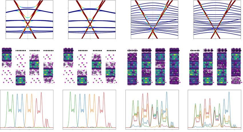
NATURE COMMUNICATIONS | https://doi.org/10.1038/s41467-020-20376-w                                                                                 ARTICLE

              a                                                                            c
                                                                       C2                              DOS                        C2
                                                                                                       PDOS Crd
                                                                                                       PDOS Ip        C1
              dI/dV (a.u.)                                   C1

                                                                                           DOS
                         -2.5 -2.0 -1.5 -1.0 -0.5      0.0     0.5    1.0   1.5      2.0
                                         Sample bias (V)
                                                                                           Κ
              b
                                                                           VD
              dI/dV (a.u.)

                                 VBM
                                                                                           Γ
                                                    -0.3 -0.2 -0.1 0.0 0.1 0.2 0.3

                                                                            CBM

                                                                                           Μ
                        -1.2   -1.0   -0.8   -0.6   -0.4     -0.2    0.0    0.2      0.4    -1.5    -1.0    -0.5    0.0     0.5        1.0   1.5
                                         Sample bias (V)                                                           E-EF (eV)
Fig. 2 The electronic structure of G/CrI3. a The dI/dV spectrum of G/FL-CrI3/Gr taken in a large sample bias window (−2.5 V ≤ Vs ≤ 2.1 V). Two
prominent double-peak features are indicated by C1 and C2, respectively. b The dI/dV spectrum of G/FL-CrI3/Gr taken in a small sample bias window
(−1.2 V ≤ Vs ≤ 0.42 V). The band edges are indicated by VBM and CBM. The inset shows the dI/dV spectrum near the Fermi level (−0.3 V ≤ Vs ≤ 0.3 V).
The local conductance minimum is indicated by VD. c Calculated density of states (DOS) and band structure of G/ML-CrI3 using Hubbard U = 0.5 eV. Both
DOS and the projected DOS (PDOS) on iodine p orbitals and chromium d orbitals are shown. The color-coding in the band structure indicates the
expectation value of spin Sz with yellow and purple corresponding to spin-up and -down, respectively.

contributed by majority-spin states (0 eV < E − EF < 0.5 eV) with                          triangular “cluster” pattern with a lattice constant of 0.69 ±
a nearly equal contribution from Cr d states and I p states, both of                       0.01 nm. We then superimposed the atomic structure of ML-CrI3
which strongly hybridize with majority-spin Dirac cones. In                                over the corresponding STM image in Fig. 3a (note that the
contrast, C2 is contributed mainly by minority-spin d states of Cr                         bottom I atoms in the atomic model are removed for clarity) for a
(0.8 eV < E − EF < 1.3 eV) with a negligible hybridization with                            close examination, which reveals that individual triangular
graphene states.                                                                           clusters are formed by three nearest I atoms in the top atomic
   We note that the Hubbard U has a negligible influence on the                             plane. In addition, the maxima of triangular cluster protrusion
overall band shape but significantly changes the energy spacing                             are located at the center of three nearest I atoms in the top atomic
between C1 and C2. It is found that the use of a Hubbard U of                              plane, equivalent to the center of the hexagon formed by six
0.5 eV yields an energy spacing around 0.8 eV between C1 and C2,                           adjacent Cr atoms. This is similar to the reported STM image of
in good agreement with that observed in the dI/dV spectra                                  CrBr321. By contrast, the STM image taken at Vs = −2.5 V
(Fig. S4). The bandgap of ML-CrI3 predicted from spin-polarized                            (Fig. 3b) shows that the maxima of the protrusion are nearly
DFT calculations is around 1.24 eV, close to the bandgap                                   located over the I atoms in the top atomic plane.
measured experimentally. Based on calculated band structures                                  Both STS and STM results indicate that graphene is almost
of G/CrI3 (Fig. 2c), it is noted that ED lies in the bottom of                             transparent to tunneling electrons when the sample bias is outside
conduction bands of CrI3 in contrast to our experimental                                   the bandgap of FL-CrI3. Otherwise, it would not be possible to
observation that ED is located inside the bandgap. Such a                                  probe the atomic structures and electronic properties of the
discrepancy is attributed to the additional charge transfer between                        underlying insulating CrI3 flake as semimetallic graphene is closer
the bottom graphite substrate and G/CrI3.                                                  to the tip by ~3.5 Å (predicted by DFT calculations). Such
   We also found that graphene and the underlying CrI3 lattice                             transparency of graphene in the tunneling process has been
can be selectively imaged by choosing an appropriate sample bias.                          observed for graphene grown on metallic substrate11–13. It turns
Figure 3a–c shows three representative bias-dependent STM                                  out that the substrate states can extend further beyond graphene
images taken on G/FL-CrI3/Gr (a full set of bias-dependent STM                             because graphene’s π states are strongly localized by both the
images is shown in Fig. S1). The honeycomb lattice of graphene                             large in-plane wave vector of graphene’s π states and the small
can be clearly resolved at low sample bias (Vs = −0.3 V) within                            out-of-plane extension of their atomic orbitals11. In the case of G/
the bandgap (Fig. 3c), while CrI3 lattice with two distinct patterns                       CrI3 heterostructure, our DFT calculations also confirm that the
can be imaged at large sample biases outside the bandgap (Fig. 3a,                         CrI3 states dominate the simulated STM images at a distance
b). STM image acquired at Vs = 2.5 V (Fig. 3a) shows a periodic                            around 4 Å above graphene surface (refer to supporting

NATURE COMMUNICATIONS | (2021)12:70 | https://doi.org/10.1038/s41467-020-20376-w | www.nature.com/naturecommunications                                       3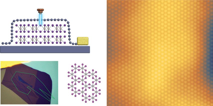
ARTICLE                                                                    NATURE COMMUNICATIONS | https://doi.org/10.1038/s41467-020-20376-w

                             a                                  b                                c    Z: Vs = -0.3V
                                     Z: Vs = 2.5V                    Z: Vs = -2.5V

                                                       1 nm                              1 nm                             1 nm
                                 Low                     High

                             d       DFT: Vs = 3.1V             e    DFT: Vs = -2V                f   Z: Vs = 0.6V

                                                                                                        0.7 nm

                                                      1 nm                               1 nm                              3 nm

                                 Low                     High

                             g                                                       h

                                                                    L2
                                         L1
                                 a
                                                                                         a
                                 b Rhombohedral                 Monoclinic                   b

Fig. 3 STM measurements of G/FL-CrI3/Gr. a–c Bias-dependent STM images of G/FL-CrI3/Gr. STM images taken at (a) Vs = 2.5 V and (b) at Vs = −2.5 V
with the superimposed atomic structure of ML-CrI3 (I atoms on the bottom atomic plane are removed for clarity). STM images taken at (c) Vs = −0.3 V.
The tunneling current is It = 1 nA. d, e Simulated STM images taken at (d) Vs = 3.1 V and (e) Vs = −2 V with the superimposed atomic structure of ML-CrI3.
f STM image acquired across the single-layer step of CrI3 (Vs = 0.6 V, It = 0.2 nA). g The atomic structure of adjacent CrI3 layers with rhombohedral
stacking and monoclinic stacking. The upper (lower) panels are side (top) views. The top view shows the honeycomb lattice formed by Cr atoms (I atoms
are removed for clarity), where the center of each hexagon in the upper (lower) layer is indicated by the red (blue) circle. h The processed STM image of
f by using edge enhancement filters to better visualize the atomic lattice of both layers. The lattice of the upper (lower) layer is represented by the red
(blue) circle. To intuitively show the atomic translation between two layers, a replica of the upper-layer lattice (translated by (8a + 16b) with respect to the
original lattice of the upper layer) is shown as the red circle on the lower layer. The red arrow represents the vector (8a + 16b).

information S4 for more details). However, the spatial structure                 reports have suggested that exfoliated FL-CrI3 thin flakes show
of wavefunctions in the regions of space where they have decayed                 interlayer AFM coupling below the critical temperature2,6,20,25–29.
by more than a factor of 106 becomes unreliable (Fig. S5).                       This was interpreted as FL-CrI3 exfoliated at room temperature is
Therefore, we have chosen to focus on STM simulations at                         kinetically trapped in the monoclinic phase upon cooling (which
distances of 3 Å above the graphene layer with the introduction of               favors interlayer AFM coupling)17,22,29. Such a hypothesis is
a damping weightage to mimic the structure at larger distances.                  further verified in recent works by monitoring the change in the
The simulated STM images at both positive and negative sample                    second harmonic generation of bilayer CrI3 during its AFM-to-
biases (Fig. 3d, e) show good agreement with the corresponding                   FM transition30 and phase-sensitive Raman modes of FL-CrI329.
experimental STM images (Fig. 3a, b).                                            However, direct atomic-scale visualization of the low-temperature
                                                                                 phase of exfoliated FL-CrI3 is still lacking.
Visualizing the stacking order in the exfoliated FL-CrI3.                           Here, we managed to directly visualize the monoclinic stacking
Stacking-dependent interlayer magnetism is another peculiar                      in exfoliated FL-CrI3 at low temperature by imaging the lateral
feature in 2D magnetic insulators. It has been predicted that the                translation between adjacent CrI3 layers. Figure 3g illustrates the
monoclinic stacking favors interlayer antiferromagnetic (AFM)                    top and side views of adjacent CrI3 layers with the rhombohedral
coupling, while the rhombohedral stacking favors the interlayer                  and monoclinic stacking. As shown in Fig. 3g, the lower CrI3
ferromagnetic (FM) coupling15,17,22–24. Bulk CrI3 undergoes a                    layer is laterally translated by L1 ¼ 13 a þ 23 b (L2 ¼ 13 a þ 13 b) with
structural phase transition from a monoclinic to a rhombohedral                  respect to the upper CrI3 layer for the rhombohedral (mono-
phase at 220 K accompanied with the interlayer FM coupling                       clinic) stacking17,29. The top view shows the honeycomb lattice
below the critical temperature of 61 K14. By contrast, various                   formed by Cr atoms (I atoms are removed for clarity) for two

4                  NATURE COMMUNICATIONS | (2021)12:70 | https://doi.org/10.1038/s41467-020-20376-w | www.nature.com/naturecommunications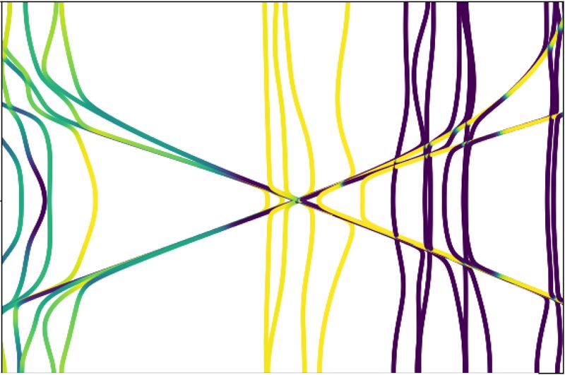
NATURE COMMUNICATIONS | https://doi.org/10.1038/s41467-020-20376-w ARTICLE
different stacking phases, where the center of each hexagon is of 3.14 ± 0.01 nm (refer to the supporting information S5 for
indicated by the red (blue) circle in the upper (lower) CrI3 layer. more details). The dark (lower) and bright (higher) regions in the
As shown in Fig. 3a, the center of each hexagon formed by six topographic STM image are defined as moiré valley and moiré
adjacent Cr atoms appears as a protrusion in the STM image hump, respectively (Fig. 4a). At zero magnetic field, the dI/dV
taken at the positive sample bias. This allows us to identify the spectra taken in valley and hump regions show a noticeable dif-
lateral translation between adjacent CrI3 layers by examining the ference in terms of the energy position and peak intensity around
STM images of both upper and lower CrI3 layer across a single- C1 states (Fig. 4e). It is noted that C1 states result from the
layer step. Figure 3f presents a typical STM image of a single-layer hybridization of majority-spin CrI3 and graphene states. There-
step in CrI3 with an expected apparent step height of 0.7 ± fore, it is very likely that the spatial variation of C1 states in valley
0.1 nm6. The CrI3 lattice in both upper and lower layers can be and hump regions is originated from the atomic registry-
better visualized in the STM image processed by the edge dependent hybridization between graphene and the underlying
enhancement filter in SPIP (Fig. 3h)31. We then identify the CrI332. The dI/dV map taken at Vs = 0.44 V also captured a
lattice of both upper and lower layers, which are represented by spatial moiré modulation of the LDOS (Fig. 4b), consistent with
the red and the blue circles, respectively (Fig. 3h). A statistical the dI/dV spectroscopic measurement. We then swept the vertical
analysis shows that the lattice of the lower layer is translated by magnetic field and monitored the moiré contrast in the dI/dV
L = (8.35 ± 0.08)a + (16.36 ± 0.06)b with respect to the lattice of maps. As shown in Fig. 4c, d, the characteristic moiré contrast
the upper layer. Taking the modulus of the translation vector L, with a nearly constant relative amplitude (defined as the differ-
the lower layer is determined to be translated by (0.35 ± 0.08)a + ence in the dI/dV signal between moiré valley and hump as
(0.36 ± 0.06)b with respect to the upper layer, which reveals the shown in Fig. S7) retains when the magnetic field gradually
monoclinic stacking in exfoliated FL-CrI3 at low temperature increases up to 1.84 T. We then ramped the sample bias from
within the experimental uncertainty. Such a stacking favors the 2.2 V to −2.2 V to perform point dI/dV spectroscopy (Fig. S8a).
interlayer AFM coupling as predicted by theory17,22–24. During the measurement, we observed a sudden change of the
I–V and dI/dV signal (Fig. S8b). By rescanning the same area at
1.84 T, we found that the characteristic moiré contrast vanished
Probing the magnetic properties of G/FL-CrI3/Gr. Apart from in the dI/dV map (Vs = 0.44 V) as shown in Fig. S8c. The mag-
the structural and electronic properties of CrI3, we also found that netic field-dependent moiré contrast in dI/dV maps (taken at
the magnetic properties of underlying FL-CrI3 can be probed fixed bias Vs = 0.44 V) is consistent with the evolution of mag-
through graphene using magnetic field-dependent STM/STS netic field-dependent full dI/dV spectra taken over moiré hump
measurements. STM image of G/FL-CrI3/Gr acquired at Vs = and moiré valley (Fig. 4e), which confirms its electronic origin.
−0.3 V (Fig. 4a) exhibits the moiré superlattice with a periodicity Upon exposing the sample to 1.84 T, the difference between the
a Z: Vs = -0.3V
b dI/dV: V = 0.44V
c 20 e Valley Hump
Amplitude (pA)
s
15 increase µ0H
10 decrease µ0H
5
2 nm 2 nm 0
0T
0 0.4 0.8 1.2 1.6 2.0
Low High Low High Magnetic field (T)
d dI/dV: V s
= 0.44V 0.87
dI/dV (a.u.)
1.30
0T 5 nm 0.87T 1.30T 1.52T
1.52
1.74
1.74T 1.84T 1.84T 1.74T
1.84
1.84
0.2 0.4 0.6 0.8 1.0 1.2
1.52T 1.30T 0.65T 0T
Sample bias (V)
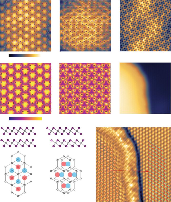
Fig. 4 Magnetic field-dependent moiré contrast in dI/dV maps. a STM image (Vs = −0.3 V, It = 0.2 nA) shows the moiré pattern of G/FL-CrI3/Gr. The
lower (higher) region is referred as moiré valley (hump) indicated by the blue (red) circle. b The corresponding dI/dV map (Vs = 0.44 V, It = 0.5 nA).
c Magnetic field-dependent moiré contrast in the dI/dV maps (Vs = 0.44 V, It = 0.5 nA). d Magnetic field-dependent dI/dV maps (Vs = 0.44V, It = 0.5 nA).
e Magnetic field-dependent dI/dV spectra taken at moiré valley (blue) and hump (red).
NATURE COMMUNICATIONS | (2021)12:70 | https://doi.org/10.1038/s41467-020-20376-w | www.nature.com/naturecommunications 5ARTICLE NATURE COMMUNICATIONS | https://doi.org/10.1038/s41467-020-20376-w
dI/dV spectra taken over moiré valley and hump vanishes and band structures reveals larger band-splitting energy of the top
they become nearly identical, consistent with the disappearance of CrI3 layer in moiré hump compared to moiré valley. This suggests
the moiré contrast in dI/dV maps. Interestingly, as the magnetic that the electronic hybridization depends strongly on the local
field gradually decreases, the moiré contrast reappears but with atomic registry between graphene and CrI3, which gives rise to a
reduced relative amplitude, resulting in a forward and backward moiré contrast in dI/dV maps for G/CrI3 under AFM interlayer
hysteresis (Fig. 4c, d). We note that the critical magnetic field to coupling.
induce the change of moiré contrasts in different regions of the In contrast, nearly all the four CrI3 layers are electronically
sample varies from 1.74 to 1.84 T (Figs. S9 and 10), presumably coupled to graphene under the FM interlayer coupling config-
due to the variation of the local environment (like demagneti- uration. This is because the bands from different CrI3 layers are
zation field or the formation of domain structures)6,28. delocalized over the entire structure (Fig. 5c, d). Although the
hybridization still depends on the atomic registry between gra-
phene and individual CrI3 layers, the moiré contrast created by
Discussion each of the CrI3 layers in graphene is now shifted by a third of the
The magnetic field-dependent moiré contrast in the dI/dV maps moiré period (due to monoclinic stacking) and thus cancels each
is likely to be associated with the AFM-to-FM transition in FL- other. This explains why the transition to the FM state is seen as
CrI3: the critical magnetic field observed is very close to the the disappearance of the moiré structure.
typical magnetic field required to align all the spins in different In conclusion, we have demonstrated a new approach to probe
layers of FL-CrI3 (Fig. S11)2,15,20,29,33,34. This hypothesis is fur- the atomic lattice, intrinsic electronic structure, and interlayer
ther corroborated by our spin-polarized DFT calculation of the magnetism of mechanically exfoliated FL-CrI3 in a graphene-
atomic registry-dependent band structure of G/four-layer CrI3 encapsulated vdW vertical heterostructure using STM/STS. Our
under AFM and FM interlayer coupling. results show that overlaid graphene not only protects exfoliated
Figure 5 shows the calculated band structures of G/four-layer FL-CrI3 from degradation but also allows STM characterization
CrI3 (monoclinic phase) with two atomic arrangements (corre- of the underlying FL-CrI3 due to its peculiar transparency to
sponding to the hump and valley) under two magnetic config- tunneling electrons. The use of semimetallic graphene as a cap-
urations (corresponding to FM and AFM interlayer coupling) ping layer with electronic transparency to tunneling electrons
(refer to S8 for more details). For the AFM interlayer coupling fulfills the growing demand for the atomic-scale characterization
configurations, only the top CrI3 layer shows a noticeable elec- of the artificially assembled vdW heterostructures based on air-
tronic coupling to graphene in both moiré hump and valley sensitive 2D magnetic insulators toward next-generation spin-
regions, as visualized in Fig. 5a, b. The bands of individual CrI3 tronic devices.
layers in AFM-coupled configuration are nearly degenerate and
strongly localized in the individual CrI3 layer due to a weak
interlayer hybridization (Fig. 5a, b). Because of this, only the Methods
Sample preparation. The sample is prepared using a well-established dry transfer
bands of the top CrI3 layer hybridize with graphene states and are technique in the glove box. The mechanically exfoliated FL-CrI3 flake is sand-
split off from bands of other CrI3 layers. A careful analysis of the wiched between a top graphene layer and a bottom graphite flake. The thickness of
Fig. 5 The atomic registry-dependent band structure of G/four-layer CrI3 under AFM and FM interlayer coupling. a–d The band structure and norm-
squared wavefunctions of bands in G/four-layer CrI3 with FM and AFM interlayer order in the hump and valley geometries. The top panel shows the band
structure of G/four-layer CrI3. We indicate four states using red dashed lines shown in each of the four cases. The middle panel shows contour plots of the
norm-squared wavefunctions of indicated states averaged over the y-direction of the heterostructure. The bottom panel shows the norm-squared
wavefunctions of indicated states averaged over the entire plane.
6 NATURE COMMUNICATIONS | (2021)12:70 | https://doi.org/10.1038/s41467-020-20376-w | www.nature.com/naturecommunicationsNATURE COMMUNICATIONS | https://doi.org/10.1038/s41467-020-20376-w ARTICLE
FL-CrI3 flake is estimated to be ~8–10 nm via the analysis of the corresponding 25. Jiang, S., Li, L., Wang, Z., Mak, K. F. & Shan, J. Controlling magnetism in 2D
optical contrast. The sample is subjected to UHV annealing at 150 °C for 4 h to CrI3 by electrostatic doping. Nat. Nanotechnol. 13, 549–553 (2018).
ensure the surface cleanness for the STM study. 26. Jiang, S., Li, L., Wang, Z., Shan, J. & Mak, K. F. Spin tunnel field-effect
transistors based on two-dimensional van der Waals heterostructures. Nat.
STM and STS measurements. Our STM and STS measurements were conducted Electron. 2, 159–163 (2019).
at 4.5 K in the Createc LT-STM system with a base pressure lower than 10–10 mbar. 27. Jiang, S., Shan, J. & Mak, K. F. Electric-field switching of two-dimensional van
The tungsten tip was calibrated spectroscopically against the surface state of Au der Waals magnets. Nat. Mater. 17, 406–410 (2018).
(111) substrate. A superconducting coil was used to apply the out-of-plane external 28. Thiel, L. et al. Probing magnetism in 2D materials at the nanoscale with
magnetic field with a maximum field of 1.84 T. All the dI/dV spectra were mea- single-spin microscopy. Science 364, 973–976 (2019).
sured through a standard lock-in technique with a modulated voltage of 5–10 mV 29. Li, T. et al. Pressure-controlled interlayer magnetism in atomically thin CrI3.
at the frequency of 700–900 Hz. Nat. Mater. 18, 1303–1308 (2019).
30. Sun, Z. et al. Giant nonreciprocal second-harmonic generation from
antiferromagnetic bilayer CrI3. Nature 572, 497–501 (2019).
Data availability 31. Metrology, I. Scanning probe image processor (SPIP). User’s and Reference
The data that support the findings of this study are available from the authors on Guide (2018).
reasonable request, see “Author contributions” for specific data sets. 32. Tong, Q., Chen, M. & Yao, W. Magnetic proximity effect in a van der Waals
Moiré superlattice. Phys. Rev. Appl. 12, 024031 (2019).
Received: 13 June 2020; Accepted: 23 November 2020; 33. Zhong, D. et al. Van der Waals engineering of ferromagnetic semiconductor
heterostructures for spin and valleytronics. Sci. Adv. 3, e1603113 (2017).
34. Song, T. et al. Switching 2D magnetic states via pressure tuning of layer
stacking. Nat. Mater. 18, 1–5 (2019).
References
1. Gibertini, M., Koperski, M., Morpurgo, A. F. & Novoselov, K. S. Magnetic 2D Acknowledgements
materials and heterostructures. Nat. Nanotechnol. 14, 408–419 (2019). J.L. acknowledges the support from MOE Tier 2 grant (MOE2017-T2-1-056 and R-143-
2. Song, T. et al. Giant tunneling magnetoresistance in spin-filter van der Waals 000-A75-114) and NAMIC grant 2019014. M.K. acknowledges support from the Russian
heterostructures. Science 360, 1214–1218 (2018). Science Foundation (grant # 16-19-10557) and the Ministry of Science and Higher
3. Gong, C. & Zhang, X. Two-dimensional magnetic crystals and emergent Education of the Russian Federation (0714-2020-0002). K.S.N. also acknowledges sup-
heterostructure devices. Science 363, eaav4450 (2019). port from EU Flagship Programs (Graphene CNECTICT-604391 and 2D-SIPC Quan-
4. Geim, A. K. & Grigorieva, I. V. Van der Waals heterostructures. Nature 499, tum Technology), European Research Council Synergy Grant Hetero2D, the Royal
419–425 (2013). Society, and EPSRC grants EP/N010345/1, EP/P026850/1, and EP/S030719/1.
5. Novoselov, K. S., Mishchenko, A., Carvalho, A. & Neto, A. H. C. 2D materials
and van der Waals heterostructures. Science 353, aac9439 (2016).
6. Huang, B. et al. Layer-dependent ferromagnetism in a van der Waals crystal
Author contributions
K.S.N. and J.L. supervised the projects. Z.Q. performed the STM measurements. H.F. and
down to the monolayer limit. Nature 546, 270–273 (2017).
H.Y. helped with the STM measurements. Z.Q., K.S.N., and J.L. analyzed the results.
7. Ghazaryan, D. et al. Magnon-assisted tunnelling in van der Waals
M.H. fabricated the device with contribution from M.K. T.O. performed the theoretical
heterostructures based on CrBr3. Nat. Electron. 1, 344–349 (2018).
simulation. P.L. and J.L. helped to prepare the sample for the STM study. K.S.N., J.L., and
8. Cai, X. et al. Atomically thin CrCl3: an in-plane layered antiferromagnetic
Z.Q. prepared the paper with contribution from T.O. All authors contributed to the
insulator. Nano Lett. 19, 3993–3998 (2019).
scientific discussion and helped in writing the paper.
9. Gong, C. et al. Discovery of intrinsic ferromagnetism in two-dimensional van
der Waals crystals. Nature 546, 265–269 (2017).
10. Qiu, Z. et al. Giant gate-tunable bandgap renormalization and excitonic effects Competing interests
in a 2D semiconductor. Sci. Adv. 5, eaaw2347 (2019). The authors declare no competing interests.
11. González-Herrero, H. C. et al. Graphene tunable transparency to tunneling
electrons: a direct tool to measure the local coupling. ACS Nano 10,
5131–5144 (2016). Additional information
12. Tesch, J. et al. Structural and electronic properties of graphene nanoflakes on Supplementary information is available for this paper at https://doi.org/10.1038/s41467-
Au (111) and Ag (111). Sci. Rep. 6, 23439 (2016). 020-20376-w.
13. Leicht, P. et al. In situ fabrication of quasi-free-standing epitaxial graphene
nanoflakes on gold. ACS Nano 8, 3735–3742 (2014). Correspondence and requests for materials should be addressed to K.S.N. or J.L.
14. McGuire, M. A., Dixit, H., Cooper, V. R. & Sales, B. C. Coupling of crystal
structure and magnetism in the layered, ferromagnetic insulator CrI3. Chem. Peer review information Nature Communications thanks the anonymous reviewer(s) for
Mater. 27, 612–620 (2015). their contribution to the peer review of this work.
15. Wang, Z. et al. Very large tunneling magnetoresistance in layered magnetic
semiconductor CrI3. Nat. Commun. 9, 1–8 (2018). Reprints and permission information is available at http://www.nature.com/reprints
16. Zhang, Y. et al. Giant phonon-induced conductance in scanning tunnelling
spectroscopy of gate-tunable graphene. Nat. Phys. 4, 627 (2008). Publisher’s note Springer Nature remains neutral with regard to jurisdictional claims in
17. Jiang, P. et al. Stacking tunable interlayer magnetism in bilayer CrI3. Phys. Rev. published maps and institutional affiliations.
B 99, 144401 (2019).
18. Cardoso, C., Soriano, D., García-Martínez, N. A. & Fernández-Rossier, J. Van
der Waals spin valves. Phys. Rev. Lett. 121, 067701 (2018). Open Access This article is licensed under a Creative Commons
19. Zhang, J. et al. Strong magnetization and Chern insulators in compressed Attribution 4.0 International License, which permits use, sharing,
graphene/CrI3 van der Waals heterostructures. Phys. Rev. B 97, 085401 (2018). adaptation, distribution and reproduction in any medium or format, as long as you give
20. Klein, D. R. et al. Probing magnetism in 2D van der Waals crystalline appropriate credit to the original author(s) and the source, provide a link to the Creative
insulators via electron tunneling. Science 360, 1218–1222 (2018). Commons license, and indicate if changes were made. The images or other third party
21. Chen, W. et al. Direct observation of van der Waals stacking–dependent material in this article are included in the article’s Creative Commons license, unless
interlayer magnetism. Science 366, 983–987 (2019). indicated otherwise in a credit line to the material. If material is not included in the
22. Sivadas, N., Okamoto, S., Xu, X., Fennie, C. J. & Xiao, D. Stacking-dependent article’s Creative Commons license and your intended use is not permitted by statutory
magnetism in bilayer CrI3. Nano Lett. 18, 7658–7664 (2018). regulation or exceeds the permitted use, you will need to obtain permission directly from
23. Soriano, D., Cardoso, C. & Fernández-Rossier, J. Interplay between interlayer the copyright holder. To view a copy of this license, visit http://creativecommons.org/
exchange and stacking in CrI3 bilayers. Solid State Commun. 299, 113662 (2019). licenses/by/4.0/.
24. Jang, S. W., Jeong, M. Y., Yoon, H., Ryee, S. & Han, M. J. Microscopic
understanding of magnetic interactions in bilayer CrI3. Phys. Rev. Mater. 3,
031001 (2019). © The Author(s) 2021
NATURE COMMUNICATIONS | (2021)12:70 | https://doi.org/10.1038/s41467-020-20376-w | www.nature.com/naturecommunications 7You can also read