3D Shape Engineering and Design Parameterization
←
→
Page content transcription
If your browser does not render page correctly, please read the page content below
681
3D Shape Engineering and Design Parameterization
Kuang-Hua Chang1 and Chienchih Chen2
1
University of Oklahoma, khchang@ou.edu
University of Oklahoma, chienchih.chen-1@ou.edu
2
ABSTRACT
This paper presents a brief review and technical advancement on 3D shape
engineering and design parameterization in reverse engineering, in which discrete
point clouds are converted into feature-based parametric solid models. Numerous
efforts have been devoted to developing technology that automatically creates NURBS
surface models from point clouds. Only very recently, the development was extended
to support parametric solid modeling that allows significant expansion on the scope of
engineering assignments. In this paper, underlying technology that enables such
advancement in 3D shape engineering and design parameterization is presented.
Software that offers such capabilities is evaluated using practical examples.
Observations are presented to conclude this study.
Keywords: reverse engineering, design parameterization, auto-surfacing.
DOI: 10.3722/cadaps.2011.681-692
1 INTRODUCTION
3D scanning technology has made enormous progress in the past 25 years [1]; especially, the non-
contact optical surface digitizers. These scanners or digitizers become more portable, affordable; and
yet capturing points faster and more accurately. A hand-held laser scanner captures tens of thousands
points per second with a level of accuracy around 40 m, and can cost as low as fifty thousand dollars,
such as a ZScanner 800 [2]. Such technical advancement makes the scanners become largely accepted
and widely used in industry and academia for a broad range of engineering assignments. As a result,
demand on geometric modeling technology and software tools that support efficiently processing large
amount of data points and converting them into useful forms, such as NURBS (non-uniform rational B-
spline) surfaces, become increasingly higher.
Auto-surfacing technology that automatically converts point clouds into NURBS surface models
has been developed and implemented into commercial tools, such as Geomagic [3], Rapidform [4],
PolyWorks [5], SolidWorks/Scan to 3D [6], among many others. These software tools have been
routinely employed to create NURBS surface models with excellent accuracy, saving significant time
and effort. The NURBS surface models are furnished with geometric information that is sufficient to
support certain types of engineering assignments in maintenance, repair, and overhaul (MRO)
industry, such as part inspection and fixture calibration. The surface models support 3D modeling for
bioengineering and medical applications, such as [7-10]. They also support automotive industry and
aerospace design [11]. NURBS surface models converted from point clouds have made tremendous
Computer-Aided Design & Applications, 8(5), 2011, 681-692
© 2011 CAD Solutions, LLC, http://www.cadanda.com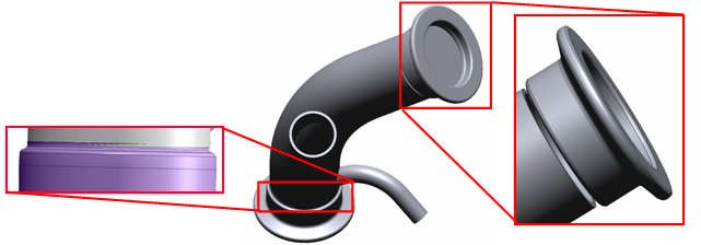
682
contributions to wide range of engineering applications. However, these models contain only surface
patches without the additional semantics and topology inherent in feature-based parametric
representation. Therefore, they are not suitable for design changes, feature-based NC toolpath
generations, and technical data package preparation. Part re-engineering that involves design changes
also requires parametric solid models.
Shape engineering and design parameterization aims at creating fully parametric solid models
from scanned data points and exporting them into mainstream CAD packages that support part re-
engineering, feature-based NC toolpath generations, and technical data package preparation. Although,
converting data points into NURBS surface models has been automated, creating parametric solid
models from data points cannot and will not be fully automated. This is because that, despite
technical challenges in implementation, the original design intent embedded in the data points must
be recovered and realized in the parametric solid model. Modeling decisions have to be made by the
designer in order to recover the original design intents. However, designers must be relieved from
dealing with tedious point data manipulations and primitive geometric entity constructions. Therefore,
the ideal scenario is having software tools that take care of labor intensive tasks, such as managing
point cloud, triangulation, etc., in an automated fashion; and offer excellent capabilities to allow
designers to recover design intents interactively. Such an ideal scenario has been investigated for
many years. After these many years, what can be done with the technology and tools developed up to
this point? Many papers already address auto-surfacing. In this paper, we will focus on solid modeling
and design parameterization.
2 DESIGN PARAMETERIZATION
One of the common approaches for searching for design alternatives is to vary the part size or shape
of the mechanical system. In order to vary part size or shape for exploring better design alternatives,
the parts and assembly must be adequately parameterized to capture design intents.
At the parts level, design parameterization implies creating solid features and relating dimensions
so that when a dimension value is changed the part can be rebuilt properly and the rebuilt part
revealed design intents. At the assembly level, design parameterization involves defining assembly
mates and relating dimensions across parts. When an assembly is fully parameterized, a change in
dimension value can be automatically propagated to all parts affected. Parts affected must be rebuilt
successfully, and at the same time, they will have to maintain proper position and orientation with
respect to one another without violating any assembly mates or revealing part penetration or excessive
gaps. For example, in a single-piston engine shown in Fig. 1. [12], a change in the bore diameter of the
engine case will alter not only the geometry of the case itself, but also all other parts affected, such as
the piston, piston sleeve, and even the crankshaft. Moreover, they all have to be rebuilt properly and
the entire assembly must stay intact through assembly mates, and faithfully reveal design intents.
Cylinder fins
Cylinder Bore diameter
head Bore diameter 1.6"
1.2"
Cylinder Larger
sleeve diameter
Piston
Longer
Crankshaft
Engine case
Wider
Fig. 1: A single-piston engineexploded view, (a) bore diameter 1.2", and (b) bore diameter 1.6".
Computer-Aided Design & Applications, 8(5), 2011, 681-692
© 2011 CAD Solutions, LLC, http://www.cadanda.com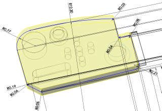
683
3 SHAPE ENGINEERING
The overall process of shape engineering and parametric solid modeling is shown in Fig. 2., in which
four main phases are involved. They are (1) triangulation that converts data points to polygon mesh, (2)
mesh segmentation that separates polygon mesh into regions based on the characteristics of the
surface geometry they respectively represent, (3) solid modeling that converts segmented regions into
parametric solid models, and (4) model translation that exports solid models constructed to
mainstream CAD systems. Note that it is desired to have the entire process fully automated; except for
Phase 3. This is because that, as stated earlier, Phase 3 requires designer’s interaction mainly to
recover original design intents. These four phases are briefly discussed in the following subsections.
Triangulation Segmentation Solid modeling Model translation
Point cloud Polygon mesh Segmented regions Parametric Model translated
solid model in CAD
Fig. 2: General process of shape engineering and parametric solid model construction.
3.1 Triangulation
The mathematic theory and computational algorithms for triangulation have been well developed in
the past few decades. A polygon mesh can be automatically and efficiently created for a given set of
data points. The fundamental concept in triangulation is Delaunay triangulation. In addition to
Delaunay triangulation, there are several well-known mathematic algorithms for triangulation,
including marching cubes [13], alpha shapes [14], ball pivoting algorithm (BPA) [15], Poisson surface
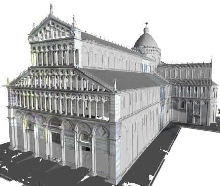
reconstruction [16], moving least squares [17], etc. A few high profile projects yield excellent results,
such as sections of Michelangelo’s Florentine Pietà composed of 14M triangle mesh generated from
more than 700 scans [15], reconstruction of “Pisa Cathedral” (Pisa, Italy) from laser scans with over
154M samples [17], and head and cerebral structures (hidden) extracted from 150 MRI slices using
marching cubes algorithm (about 150,000 triangles), as shown in Fig. 3.
Fig. 3: Sample projects of scanning and triangulation, (a) Michelangelo’s Florentine Pietà, (b) Pisa
Cathedral, and (c) head and cerebral structures.
3.2 Segmentation
One of the most important steps in shape engineering is mesh segmentation. Segmentation groups the
original data points or mesh into subsets each of which logically belongs to a single primitive surface.
In general, segmentation is a complex process. Often iterative region growing techniques are
applied [18-20]. Some use non-iterative methods, called direct segmentation [21], that are more
efficient. In general, the segmentation process, such as [22], involves a fast algorithm for k-nearest
neighbors search and an estimate of first- and second-order surface properties. The first-order
segmentation, which is based on normal vectors, provides an initial subdivision of the surface and
Computer-Aided Design & Applications, 8(5), 2011, 681-692
© 2011 CAD Solutions, LLC, http://www.cadanda.com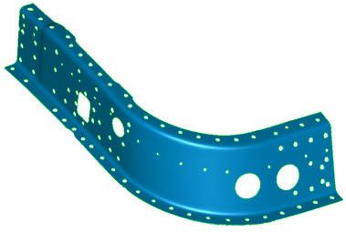
684

detects sharp edges as well as flat or highly curved areas. The second-order segmentation subdivides
the surface according to principal curvatures and provides a sufficient foundation for the
classification of simple algebraic surfaces. The result of the mesh segmentation is subject to several
important parameters, such as the k value (number of neighboring points chosen for estimating
surface properties), and prescribed differences in the normal vectors and curvatures (also called
sensitivity thresholds) that group the data points or mesh. As an example shown in Fig. 4(a)., a high
sensitive threshold leads to scattered regions of small sizes, and a lower sensitive threshold tends to
generate segmented regions that closely resemble the topology of the object, as illustrated in Fig. 4(b).

                              Scattered regions                        Regions of plane surface

Fig. 4: Example of mesh segmentation, (a) an object segmented into many small regions due to a high
sensitivity threshold, and (b) regions determined with a low sensitivity threshold.

    Most of the segmentation algorithms come with surface fitting, which fits best primitive surface of
an appropriate type to each segmented regions. It is important to specify a hierarchy of surface types
in the order of geometric complexity, similar to that of Fig. 5. [23]. In general, objects are bounded by
relatively large primary (or functional) surfaces. The primary surfaces may meet each other along
sharp edges or there may be secondary or blending surfaces which may provide smooth transitions
between them.

                                                      Surfaces

                            Primary geometry                                Secondary geometry

  Simple surfaces      Regular sweep surfaces     Free-form surfaces
                                                                                  Edge blends

        Planes                    Translational sweeps                            Vertex blends

        Natural quadrics          Rotational sweeps
                                  (revolved)
        Tori
                                    Fig. 5: A hierarchy of surfaces.

    As discussed above, feature-based segmentation provides a sufficient foundation for the
classification of simple algebraic surfaces. Algebraic surfaces, such as planes, natural quadrics (such
as sphere, cylinders, and cones), and tori, are readily to be fitted to such regions. Several methods,
including [24], have been proposed to support such fitting, using least square fitting.
     In addition to primitive algebraic surfaces, more general surfaces with a simple kinematic
generation, such as sweep surfaces, revolved surfaces (rotation sweep), extrusion surfaces (translation
sweep), pipe surfaces, are directly compatible to CAD models. Fitting those surfaces to segmented data
points or mesh is critical to the reconstruction of surface models and support of parameterization
[25].
    In some applications, not all segmented regions can be fitted with primitives or CAD-compatible
surfaces within prescribed error margin. Those remaining regions are classified as freeform surfaces,
where no geometric or topological regularity can be recognized. These can be a collection of patches

                                            Computer-Aided Design & Applications, 8(5), 2011, 681-692
                                                © 2011 CAD Solutions, LLC, http://www.cadanda.com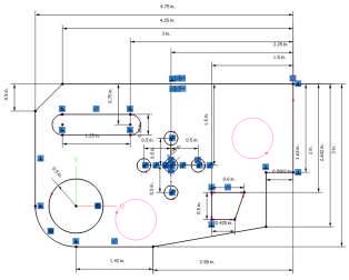
685
or possibly trimmed patches. They are often fitted with NURBS surfaces. Many algorithms and
methods have been proposed to support NURBS surface fitting, such as [26].
3.3 Solid Modeling
Solid modeling is probably the least developed in the overall shape engineering process. Boundary
representation (B-rep) and feature-based are the two basic representations for solid models. There has
been some methods, such as [21], proposed to automatically construct B-rep models from point clouds
or triangular mesh. Some focused on manufacturing feature recognition for process planning purpose,
such as [27]. One promising development in recent years was the geometric feature recognition (GFR),
which automatically recognizes solid features embedded in B-rep models. However, none of the
method is able to fully automate the construction process and generate fully parametric solid models.
Some level of manual work is expected.
3.3.1 Boundary Representation
Based on segmented regions (with fitted surfaces), a region adjacent graph is built, which reflects the
complete topology and serves as the basis for building the final B-rep model, also called stitched
models, where the individual bounded surfaces are glued together along their common edges.
In general, there are three steps involved in constructing B-rep models, flattening, edges and
vertices calculations, and stitching [21]. In flattening step, regions are extended outwards until all
triangles have been classified. Note that this step is necessary to remove all gaps between regions.
Sharp edges can be calculated using surface-surface intersection routines, and vertices where three
surfaces meet are also determined. During the process, a complete B-rep topology tree is also
constructed. A B-rep model can then be created by stitching together the faces, edges, and vertices.
This operation is commonly supported by most solid modeling kernels.
3.3.2 Geometric Feature Recognition
B-rep models are not feature-based. In order to convert a B-rep model into a feature-based solid model,
the embedded solid features must be recognized, and a feature tree that describes the sequence of
feature creation must be created.
One of the most successful algorithms for geometric feature recognition has been proposed by
Venkataraman [28]. The algorithm uses a simple four step process, (1) simplify imported faces, (2)
analyze faces for specific feature geometry, (3) remove recognized feature and update model; and (4)
return to Step 2 until all features are recognized. The process is illustrated in Fig. 6. Once all possible
features are recognized, they are mapped to a new solid model of the part (Fig. 6(d).) which is
parametric with a feature tree that defines the feature regeneration (or model rebuild) sequence.
Fig. 6: Illustration of GFR algorithm, (a) imported surface model with hole surface selected, (b) hole
recognized and removed, extruded face of cylinder selected, (c) cylindrical extrusions recognized, base
block extrusion face selected, and (d) all features recognized and mapped to solid model.
Venkataraman’s method was recently commercialized by Geometric Software Solutions, Ltd. (GSSL)
[29], and implemented in a number of CAD packages, including SolidWorks and CATIA, capable of
recognizing basic features, such as extrude, revolve, and more recently, sweep. This capability has
been applied primarily for support of solid model translations between CAD packages with some
success, in which not only geometric entities (as has been done by IGESInitial Graphics Exchange
Standards) but also parametric features are translated.
Computer-Aided Design & Applications, 8(5), 2011, 681-692
© 2011 CAD Solutions, LLC, http://www.cadanda.com686
One of the major issues revealed in commercial GFR software is design intent recovery. For
example, the flange of airplane tubing would be recognized as a single revolve feature, where a sketch
is revolved about an axis (Fig. 7(a).). However, current GFR implementations are not flexible. As shown
in Fig. 7(b)., without adequate user interaction, the single sketch flange may be recognized as four or
more separate features. While the final solid parts are physically the same, their defining parameters
are not. Such a batch mode implementation may not be desired in recovering meaningful design
intents.
Axis of
Revolution
Profile
Sketch 1. Revolve feature 2. Extrude Feature Added 3. Cut feature Added 4. Fillets Added
Fig. 7: Feature recognition for airplane tubing flange, (a) single revolved feature, and (b) four features:
revolve, extrude, cut, and fillet.
3.3.3 Design Parameterization
A feature-based parametric solid model consists of two key elements: a feature tree, and fully
parameterized sketches employed for protruding solid features. A fully parameterized sketch implies
that the sketch profile is fully constrained and dimensioned, so that a change in dimension value yields
a rebuilt as anticipated with design intents. To the authors’ knowledge, there is no such method
proposed or offered that fully automates the process. Some capabilities are offered by commercial
tools, such as Rapidform, that support designers to interactively create fully parameterized sketches,
which accurately conform to the data points and greatly facilitates the solid modeling effort.
3.4 Solid Model Translations
Since most of the promising shape engineering capabilities are not offered in CAD packages (more
details in the next section), the solid models constructed in these reverse engineering software will
have to be exported to mainstream CAD packages in order to support common engineering
assignments. The conventional solid model translation via standards, such IGES or STEP AP
(application protocols), are inadequate since parametric information, including solid features, feature
tree, sketch constraints and dimensions, are completely missing in the translation. Although feature
recognition capability offers some relief in recognizing geometric features embedded in B-rep models,
it is still an additional step that is often labor intensive. Direct solid model translations have been
offered in some software, such as liveTransfer™ module of Rapidform XOR3 and third party software,
such as TransMagic [30]. More will be discussed for liveTransfer™.
4 ENGINEERING SOFTWARE
The most useful and advanced shape engineering capabilities are offered in specialized, non-CAD
software, such as Geomagic, Rapidform, etc., that are intended to support reverse engineering. Some
CAD packages, such as SolidWorks, Pro/ENGINEER Wildfire, and CATIA, offer limited capabilities for
shape engineering. In general, capabilities offered in CAD are labor intensive and inferior to
specialized codes while dealing with shape engineering.
After intensive review and survey [31], to the authors’ knowledge, the best software on the market
for reverse engineering is Geomagic Studio v.11 and Rapidform XOR3. This was determined after a
thorough and intensive study, following a set of prescribed criteria including auto-surfacing,
parametric solid modeling, and software usability. Between the two, Geomagic has a slight edge in
geometric entity editing, which is critical for auto-surfacing (construction NURBS surface models). In
terms of solid modeling, Geomagic stops short at only offering primitive surfaces, such as plane,
cylinder, sphere, etc., from segmented regions.
Computer-Aided Design & Applications, 8(5), 2011, 681-692
© 2011 CAD Solutions, LLC, http://www.cadanda.com687
Rapidform is superior in support of solid modeling (in addition to excellent auto-surfacing) that
goes beyond primitive surface fitting. Rapidform offers convenient sketching capabilities that support
feature-based modeling. As a result, it often requires less effort yet yielding a much better solid model
by interactively recovering solid features embedded in the segmented regions. The interactive
approach mainly involves creating or extracting section profiles or guide curves from polygon mesh,
and following CAD-like steps to create solid features; for example, sweep a section profile along guide
curves for a sweep solid feature. For example, an airplane sheet metal part was constructed by lofting
two end section profiles with four guide curves, as shown in Fig. 8. The loft model is very accurate. As
shown in Fig. 8(c)., the geometric error in average and standard deviation between the lofted model
and the polygon mesh are -0.021 and 0.049 in., respectively (using Accuracy Analyzer of Rapidform).
Section Guide curves: extracted
profile from boundary of
segmented regions
Section
Guide curves profile
extracted from
part boundary
Fig. 8: Lofted model of sheet metal part (16in.×10in.×9in.), (a) polygon mesh of 134,089 polygons, (b)
lofted model using two section profiles and four guide curves, and (c) geometric error analysis.
5 TEST EXAMPLES
Focus of the paper is given to feature-based solid modeling. Only selected examples for Geomagic and
Rapidform are presented to illustrate the detailed steps and essential capabilities in the software.
5.1 Geomagic Studio v.11
Geomagic automatically recognizes primitive surfaces from segmented regions. If a primitive surface is
misrecognized or unrecognizable, users are able to interactively choose the segmented region and
assign a correct primitive type. Often, this interactive approach leads to a solid model with all
bounding surfaces recognized. Unfortunately, there is no feature tree, and no CAD-like capabilities in
Geomagic. Users will not be able to see any sketch or dimensions in Geomagic Studio v.11. Therefore,
users will not be able to edit or add any dimensions or constraints to parameterize the sketch profiles.
Section sketches only become available to the users after exporting the solid model to a selected CAD
package supported by Geomagic.
The block example (3in.×5in.×0.5in.) of 634,957 points shown in Fig. 4. is employed to illustrate
the capabilities offered in Geomagic. As shown in Fig. 9(a)., primitive surfaces in most regions are
recognized correctly. However, there are some regions incorrectly recognized; for example, the hole in
the middle of the block was recognized as a free-form primitive, instead of a cylinder. There are also
regions remained unrecognized; e.g., the middle slot surface.
Although most primitives are recognized in Geomagic, there are still issues to address. One of
them is misrepresented profile. One example is that a straight line in a sketch profile may be
recognized as a circular arc with a large radius, as shown in Fig. 9(b). (this was found only after
exporting the solid model to SolidWorks). The sketch profile will have to be carefully inspected to make
necessary corrections, as well as adding dimensions and constraints to parameterize the profile.
Unfortunately, such inspections cannot be carried out unless the solid model is exported to supported
CAD systems. Lack of CAD-like capability severely restricts the usability of the solid models in
Geomagic, let alone the insufficient ability for primitive surface recognition.
5.2 Rapidform XOR3
Rapidform offers much better capabilities than Geomagic for parametric solid modeling. Excellent
CAD-like capabilities, including feature tree, are available to the users. These capabilities allow users to
create solid models and make design changes directly in Rapidform. For example, users will be able to
Computer-Aided Design & Applications, 8(5), 2011, 681-692
© 2011 CAD Solutions, LLC, http://www.cadanda.com688
create a sketch profile by intersecting a plane with polygon mesh, and extrude the sketch profile to
match the bounding polygon mesh for a solid feature. On the other hand, with the feature tree users
can always roll back to previous entities and edit dimensions or redefine section profiles. These
excellent capabilities make Rapidform particularly suitable for parametric solid modeling. Rapidform
offers two methods for solid modeling, Sketch, and Wizard, which offers fast and easy primitive
recognition from segmented mesh. The major drawback of the Wizard is that some guide curves and
profile sketch generated are non-planar spline curves that cannot be parameterized. Users can use
either or both methods to generate solid features in a single part.
Lack of
constraints
in section
profile
Rotation Free form
Cylinder
Extrusion Misrecognition: a
Plane line is recognized
Unrecognizable region as a circular arc
Fig. 9: Primitive surfaces recognized in Geomagic, (a) recognized regions, and (b) extracted primitive
surfaces in SolidWorks.
5.2.1 Method 1: Sketch
In general, there are six steps employed in using the sketch method, (1) creating reference sketch
plane, (2) extracting sketch profile by intersecting the sketch plane with the polygon mesh, (3)
converting extracted geometric entities (usually as planar spline curves) into standard line entities,
such as arcs and straight lines, (4) parameterizing the sketch by adding dimensions and constraints, (5)
extruding, revolving, or lofting the sketches to create solid features; and (6) employing Boolean
operations to union, subtract, or intersect features if necessary.
Rapidform provides Auto Sketch capability that automatically converts extracted spline curves into
lines, circles, arcs, and rectangles, with some constraints added. Most constraints and dimensions will
have to be added interactively to fully parameterize the sketch profile. Steps 4 to Step 6 are similar to
conventional CAD operations. With excellent capabilities offered by Rapidform, fully constrained
parametric solid models can be created efficiently.
For the block example, a plane that is parallel to the top (or bottom) face of the base block was
created first (by simply clicking more than three points on the surface). The plane is offset vertically to
ensure a proper intersection between the sketch plane and the polygon mesh. The geometric entities
obtained from the intersection are planar spline curves. The Auto Sketch capability of Rapidform can
be used to extract a set of standard CAD-like line entities to best fit the spline curves. These standard
line entities can be joined and parameterized by manually adding dimensions and constraints for a
fully parameterized section profile, as shown in Fig. 10(a). Once the sketch profile is parameterized, it
can be extruded to generate an extrusion feature for the base block (Fig. 10(b).). The same steps can be
followed to generate more solid features, and Boolean operations can be employed to union, subtract,
or intersect solid features for a fully parameterized solid model. The final solid model is analyzed by
using Accuracy Analyzer. The solid model generated is extremely accurate, where geometric error
measured in average and standard deviation is 0.0002 and 0.0017 in., respectively (between the solid
model and point cloud). Since the model is fully parameterized, it can be modified by simply changing
the dimensions. For example, the length of the base block can be increased for an extended model, as
shown in Fig. 10(c).
Computer-Aided Design & Applications, 8(5), 2011, 681-692
© 2011 CAD Solutions, LLC, http://www.cadanda.com689
Dimensions
Constraints
Extrusion
Length increased from 5" to 6"
Fig. 10: A parametric solid model of the block example created using Rapidform, (a) fully
parameterized section sketch, (b) extrusion for the base block, and (c) design change.
5.2.2 Method 2: Wizard
Wizard, or Modeling Wizard, of Rapidform automatically extracts Wizard features such as extrude,
revolve, pipe, and loft, etc., to create solid models from segmented regions. Note that a Wizard feature
(terminology employed in Rapidform) can be a surface (such as pipe) or a solid feature. There are five
Wizard features provided: extrusion, revolution for extracting solid features; and sweep, loft, and pipe
for surface features. There are three general steps to extract features using Wizard, (1) select mesh
segments to generate individual features using Wizard, (2) modify the dimensions or add constraints
to the sketches extracted in order to parameterize the sketches, and (3) use Boolean operations to
union, subtract, or intersect individual features for a final model if needed.
A tubing example shown in Fig. 11. is employed to illustrate the capabilities offered in Wizard. We
start with a polygon mesh that has been segmented, as shown in Fig. 11(a). First, we select the exterior
region of the main branch and choose Pipe Wizard. Rapidform uses a best fit pipe surface to fit the
main branch automatically, as shown in Fig. 11(b). Note that the Pipe Wizard generates section profile
and guide curve as spatial (non-planar) spline curves, which cannot be parameterized. Also, wall
thickness has to be added to the pipe to complete the solid feature. Next, we choose Revolution Wizard
to create revolved features for the top and bottom flanges, as shown in Fig. 11(c). Note that each
individual features are extracted separately. They are not associated. Boolean operations must be
applied to these decoupled features for a final solid model.
Main branch
Section
profile
Spatial spline curves
Fig. 11: Feature extraction for the tubing example using Wizard, (a) selected main branch region, (b)
surface created using Pipe Wizard, and (c) flange created using Revolution Wizard.
Although Wizard offers a fast and convenient approach for solid modeling, the solid models
generated are often problematic. The solid models have to be closely examined for validation. For
example, in this tubing model, there are gap and interference between features, as indicated in Fig. 12.
This is not a valid solid model. It is inflexible to edit and make changes to the Wizard features since
the sketch profile is represented in spatial spline curves that cannot be constrained or dimensioned.
In summary, Rapidform is the only reverse engineering software that supports for creating
parametric solid models from scanned data. Rapidform offers CAD-like capabilities that allow users to
Computer-Aided Design & Applications, 8(5), 2011, 681-692
© 2011 CAD Solutions, LLC, http://www.cadanda.com690
add dimensions and constraints to sketches and solid features for a fully parametric solid model. In
addition, Rapidform provides two modeling methods, Sketch and Wizard. Design intent and model
accuracy can be achieved using the Sketch method, which is in general a much better option for
creating parametric solid models.
Gap
Interference
Fig. 12: Gap and interference between solid features in the tubing model
5.3 Solid Model Translations
The solid models created in specialized software, such as Rapidform and Geomagic, have to be
translated to mainstream CAD systems in order to support engineering applications. Both Rapidform
and Geomagic offer capabilities that export solid models to numerous CAD systems.
5.3.1 Parametric Exchange of Geomagic
The solid model of the block example created in Geomagic was exported to SolidWorks and Wildfire
using Parametric Exchange of Geomagic. For SolidWorks, all seventeen features recognized in Geomagic
(see Fig. 13(a).) were translated as individual features, as shown in Fig. 13(b). Note that since there are
no Boolean operations offered in Geomagic Studio v.11, these features are not associated. There is no
relation established between them. As a result, they are just "piled up" in the solid model shown in Fig.
13(c). Subtraction features, such as holes and slots, simply overlap with the base block. Similar results
appear in Wildfire, except that one extrusion feature was not exported properly, as shown in Fig. 13(d).
and 13(e).
Feature not translated properly
Fig. 13: The block model explored to SolidWorks and Wildfire, (a) seventeen features recognized in
Geomagic, (b) features exported to SolidWorks (wireframe), (c) features "piled up" in SolidWorks, (d)
features exported to Wildfire (wireframe), and (e) features "piled up" in Wildfire.
5.3.2 liveTransfer™ module of Rapidform XOR3
The liveTransfer™ module of Rapidform XOR3 exports parametric models, directly into major CAD
systems, including SolidWorks 2006+, Siemens NX 4+, Pro/ENGINEER Wildfire 3.0+, CATIA V4 and V5
and AutoCAD.
The block example that was fully parameterized in Rapidform was first exported to SolidWorks. All
the solid features were seamlessly exported to SolidWorks, except for some datum entities, such as
datum points. Since entities such as polygon mesh and segmented regions are not included in
SolidWorks database, they cannot be exported. As a result, geometric datum features associated with
these entities are not exported properly. The dimensions and constraints added to the sketches and
solid features in Rapidform are exported well, except again for those referenced to entities that are not
available in SolidWorks. Fortunately, it only requires users to make a few minor changes (such as
adding or modifying dimensions or constraints) to bring back a fully parametric solid model in
SolidWorks. As shown in Fig. 14., the length of the base block was increased and the solid model is
rebuilt in SolidWorks (Fig. 14(b).). Similar translation results were observed in NX. However, model
Computer-Aided Design & Applications, 8(5), 2011, 681-692
© 2011 CAD Solutions, LLC, http://www.cadanda.com691
translation to Wildfire 4.0 is problematic, in which numerous issues, such as missing and
misinterpretation portion of the section profile, are encountered. In general, parametric solid models
created in Rapidform can be exported well to SolidWorks and NX. The translation is almost seamless.
Although, there were minor issues encountered, such as missing references for some datum points,
those issues can be fixed very easily.
Fig. 14: Block exported from Rapidform to SolidWorks, (a) solid model exported to SolidWorks, and (b)
design change made in SolidWorks.
6 OBSERVATIONS AND CONCLUSIONS
In this paper, technology that enables 3D shape engineering and design parameterization for reverse
engineering was briefly reviewed. Software that offers such capabilities was also evaluated and tested
using practical examples. Based on the evaluations, we observed that Rapidform is the only viable
choice for parametric solid modeling in support of 3D shape engineering and design parameterization.
Rapidform offers CAD-like capabilities for creating solid features, feature tree for allowing roll back for
feature editing, and excellent sketching functions. In addition, the liveTransfer™ module offers model
exporting to mainstream CAD systems almost seamlessly.
After research and development in decades, technology that supports 3D shape engineering and
design parameterization is matured enough to support general engineering applications. The ideal
scenario can now be realized by using software such as Rapidform for shape engineering and
parameterization, where labor intensive tasks, such as managing point cloud, triangulation, etc., is
taken care of in an automated fashion; and design intents can be recovered interactively as desired.
One area that might require more work is to incorporate more CAD packages for model export. Major
CAD packages, such as SolidWorks and NX, have been well supported. However, software such as
CATIA is yet to be included and software like Wildfire needs to be streamlined.
ACKNOWLEDGEMENT
This study was part of a reverse engineering project supported by U.S. Air Force and DRS Technologies
under Reference SOW # QIB09-008. The authors appreciate the opportunity for conducting the study.
REFERENCES
[1] Blais, F.: Review of 20 Years of Range Sensor Development, Journal of Electronic Imaging, 13(1),
2004, 231–240. DOI:10.1117/1.1631921
[2] ZScanner 800, http://www.zcorp.com, Z Corporation.
[3] Geomagic, http://www.geomagic.com, Geomagic Inc.
[4] Rapidform, http://www.rapidform.com, INUS Technology Inc.
[5] PolyWorks, http://www.innovmetric.com, InnovMetric Software Inc.
[6] SolidWorks, http://www.solidworks.com, SolidWorks Corp.
[7] Chang, K.H.; Magdum, S.; Khera, S.; Goel, V.K.: An Advanced Computer Modeling and Prototyping
Method for Human Tooth Mechanics Study, Annals of Biomedical Engineering, 31(5), 2003, 621-
631. DOI:10.114/1.1568117
[8] Sun, Q.; Chang, K.H.; Dormer, K.; Dyer, R.; Gan, R.Z.: An Advanced Computer-Aided Geometric
Modeling and Fabrication Method for Human Middle Ear, Medical Engineering and Physics, 24(9),
2002, 595-606. DOI:10.1016/S1350-4533(02)00045-0
Computer-Aided Design & Applications, 8(5), 2011, 681-692
© 2011 CAD Solutions, LLC, http://www.cadanda.com692
[9] Liu, Y.; Dong, X.; Peng, W.: Study on Digital Data Processing Techniques for 3D Medical Model,
Bioinformatics and Biomedical Engineering, 4, 2010, 1-4. DOI:10.1109/ICBBE.2010.5518168
[10] Lv, Y.; Yi, J.; Liu, Y.; Zhao, L.; Zhang, Y.; Chen, J.: Research on Reverse Engineering for Plastic
Operation, Information Technology and Applications, 2009, 389-391. DOI:
10.1109/IFITA.2009.123
[11] Raja, V.; Fernandes, K.J.: Reverse Engineering: An industrial Perspective, Springer-Verlag, London,
2008. DOI:10.1007/978-1-84628-856-2
[12] Silva, J.S.; Chang, K.H.: Design Parameterization for Concurrent Design and Manufacturing of
Mechanical Systems, Concurrent Engineering Research and Applications (CERA) Journal, 2002,
10(1), 3-14. DOI:10.1177/1063293X02010001048
[13] Lorensen, W.E.; Cline, H.E.: Marching Cubes: A High Resolution 3D Surface Construction
Algorithm, Computer Graphics, 21(4), 1987. DOI:10.1145/37402.37422
[14] Edelsbrunner, H.; Kirkpatrick, D.G.; Seidel, R.: On the Shape of A Set of Points In The Plane, IEEE
Transactions on Information Theory, 29(4), 1983, 551-559. DOI:10.1109/TIT.1983.1056714
[15] Bernardini, F.; Mittleman, J.; Rushmeier, H.; Silva, C.; Taubin, G.: The Ball-Pivoting Algorithm for
Surface Reconstruction, Visualization and Computer Graphics, 5(4), 1999, 349-359.
DOI:10.1109/2945.817351
[16] Kazhdan, M.; Bolitho, M.; Hoppe, H.: Poisson Surface Reconstruction, The Fourth Eurographics
Symposium on Geometry Processing, 2006.
[17] Cuccuru, G.; Gobbetti, E.; Marton, F.; Pajarola, R.; Pintus, R.: Fast Low-Memory Streaming MLS
Reconstruction of Point-Sampled Surfaces, Graphics Interface. 2009, 15-22.
[18] Besl, P.J.; Jain, R.C.: Segmentation Through Variable-Order Surface Fitting, IEEE Transactions on
Pattern Analysis and Machine Intelligence, 10(2), 1988, 167-192. DOI: 10.1109/34.3881
[19] Alrashdan, A.; Motavalli, S.; Fallahi, B.: Automatic Segmentation of Digitized Data for Reverse
Engineering Applications, IIE Transactions, 32(1), 2000, 59-69. DOI: 10.1023/A:1007655430826
[20] Huang, J.; Menq, C.-H.: Automatic Data Segmentation for Geometric Feature Extraction From
Unorganized 3-D Coordinate Points, IIE Transactions on Robotics and Automation, 17(3), 2001,
268-279. DOI:10.1109/70.938384
[21] Várady, T.; Benkö, P.; Kós, G.: Reverse Engineering Regular Objects: Simple Segmentation and
Surface Fitting Procedures, International Journal of Shape Modeling, 4(3-4), 1998, 127–141.
DOI:10.1142/S0218654398000106
[22] Vanco, M.; Brunnett, G.: Direct Segmentation of Algebraic Models for Reverse Engineering,
Computing, 72(1-2), 2004, 207-220. DOI:10.1007/S00607-003-0058-7
[23] Várady, T.; Martin, R.R.; Cox, J.: Reverse Engineering of Geometric Models - An Introduction,
Computer-Aided Design, 29(4), 1997, 255–268. DOI:10.1016/S0010-4485(96)00054-1
[24] Marshall, D.; Lukacs, G.; Martin, Ralph.: Robust Segmentation of Primitives from Range Data in
the Presence of Geometric Degeneracy, IEEE Transaction on Pattern Analysis and Machine
Intelligence, 23(3), 2001,304-314. DOI:10.1109/34.910883
[25] Lukács, G.; Martin, R.; Marshall, D.: Faithful Least-Squares Fitting of Spheres, Cylinders, Cones
and Tori for Reliable Segmentation, Lecture Notes in Computer Science, 1406, 1998, 671-686.
DOI:10.1007/BFb0055697
[26] Tsai, Y.C.; Huang, C.Y.; Lin, K.Y.; Lai, J.Y.; Ueng, W.D.: Development of Automatic Surface
Reconstruction Technique in Reverse Engineering, The International Journal of Advanced
Manufacturing Technology, 42(1–2), 2009, 152–167. DOI:10.1007/S00170-008-1586-2
[27] Thompson, W.B.; Owen, J.C.; de St. Germain, H.J.; Stark, S.R., Jr.; Henderson, T.C.: Featured-Based
Reverse Engineering of Mechanical Parts, IEEE Transactions on Robotics and Automation, 15(1),
1999, 57-66. DOI:10.1109/70.744602
[28] Venkataraman, S.; Sohoni, M.; Kulkarni, V.: A Graph-Based Framework for Feature Recognition,
Sixth ACM Symposium on Solid Modeling and Applications, 2001, 194-205.
DOI:10.1145/376957.376980
[29] Geometric Software Solutions, http://www.geometricglobal.com, Geometric Ltd.
[30] TransMagic, http://www.transmagic.com, TransMagic, Inc.
[31] Chang, K.H. and Chen, C., Research and Recommendation of Advanced Reverse Engineering
Tools, Final Technical Report, Reference SOW # QIB09-008, September 2010.
Computer-Aided Design & Applications, 8(5), 2011, 681-692
© 2011 CAD Solutions, LLC, http://www.cadanda.comYou can also read