Aviva Stadium:A parametric success - Paul Shepherd, Roly Hudson and David Hines
←
→
Page content transcription
If your browser does not render page correctly, please read the page content below
Aviva Stadium:A
parametric success
Paul Shepherd, Roly Hudson and David Hines

  international journal of architectural computing   issue 02, volume 09   167
Aviva Stadium:A parametric success
      Paul Shepherd, Roly Hudson and David Hines

              Abstract
              The Aviva Stadium, Dublin, is the first stadium to be designed from start
              to finish using commercially available parametric modelling software. A
              single model in Bentley’s Generative Components was shared between
              architects and engineers, which allowed the optimised design of form,
              structure and façade. The parametric software was extended where
              necessary to integrate with structural analysis and to automate
              fabrication. By reducing the overhead associated with design iterations,
              this approach allowed detailed exploration of options and early
              identification and resolution of potential problems. In this paper, the
              authors add to the body of scientific knowledge by describing in detail
              the methods which led to the construction of the Aviva Stadium.This
              paper is written in light of the completed building and provides
              information on the generation and control of the envelope geometry,
              development and analysis of structure and documentation for
              construction.Whilst these components have been discussed
              independently previously [1–4], here these aspects are drawn together
              for the first time and are presented alongside thoughts on the
              manufacturing and construction processes from the project architect.

168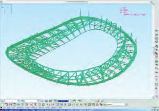
1. INTRODUCTION
1.1. Project description
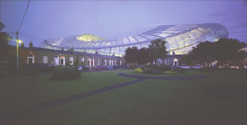
In May 2010 the new 50,000 seat Aviva Stadium at Lansdowne Road in
Dublin was officially opened, celebrating its iconic form (Figure 1) and
innovative design. The scheme design of the stadium was developed to be
both responsive and empathetic to the surrounding neighbourhood. It has
an organic translucent form, allowing the maximum amount of daylight into
the seating tiers and onto the surrounding environment, whilst minimising
the impact of the new stadium on existing buildings.The form of the
exterior skin envelops both the roof structure and the façade structure,
combining both elements into one controlling form.This concept
emphasises the importance that the form of the building had in the design
process, as it needed to accommodate all tolerances and technical
requirements of both the façade and the roof elements into one three
dimensional set-out model.
Whilst buildings have been designed using parametric modelling
techniques in the past, the first being the Barcelona Fish [5] and arguably
the most notable being the British Museum Great Court [6], such designs
were carried out using bespoke software routines written and used by an
isolated part of the design team be it architect (Barcelona Fish) or engineer
(British Museum). By the time the design concepts for the Aviva Stadium
were being formulated, a parametric approach to building modelling was just
starting to become integrated into commercially available CAD products,
allowing parametric models to be shared amongst team members and fully
integrated into established design practices.
This paper describes the way in which the project architects Populous
(formerly HOK Sport), and the structural engineers Buro Happold, were
able to produce such a complex and visually stunning building by sharing a
single parametric modelling framework which allowed rapid response to
design changes and provided full coordination between teams.
Figure 1: Photo of Aviva stadium in
the final stages of construction.
Aviva Stadium: A parametric success 169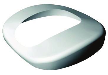
1.2. Information workflow
      Initial studies and concepts were undertaken using a combination of 3D
      programs. Firstly, using McNeel’s Rhinoceros platform, 3D models were
      created using a set of tangential arcs aligned along the radial structural grids
      of the building.This early work allowed the architects to quickly explore the
      development and logic of the form’s geometry. Once this construction logic
      had been tested around the building, the geometry of the model was rebuilt
      within Bentley’s Generative Components (GC). It’s important to note that
      at this stage the design focussed on the development of a setting-out
      geometry that corresponded to a structural grid arrayed around the
      building. All the architectural and structural elements would be related to
      this underlying geometry.The anticipation of a design evolution of the shape
      of the building through all these elements was paramount to the
      construction of the GC model.Thus certain variables and basic principles
      were established within the GC model, allowing control over the final form
      of the model to be maintained.This allowed the model to be parametric,
      having internally defined variables, but also constraining the geometry to
      certain grid-lines and limiting it to specific boundaries. For the architects,
      this was the most critical aspect of the parametric design since the finished
      construction geometry would be set-out directly from the parametric skin
      of the building.
          Having established a 3D parametric model that formed the basis for the
      setting out of the façade and the roof structure, attention was then focused
      on the implementation of all other elements from this controlling shape.
      Through a close collaboration between the architects and the structural
      engineers (Buro Happold), the setting out principles by which the structural
      roof members would relate to the parametric skin were established. A
      framework was developed, by which the information could be exchanged
      between both parties, but with the architects ultimately driving the overall
      form and cladding of the building, and with the engineers driving the
      structural member sizing / positioning (Figure 2). To achieve this, a single
      GC script was produced to generate the set-out geometry, which
      referenced an external Excel spreadsheet containing the defining
      parameters.This set-out script was then used as the basis for design by
      both architects and engineers. Thus both parties could work simultaneously
      on the model in different offices, the engineers further developing the
      structural members by extending the original GC script file and the
      architects separately developing the original script to define the cladding
      layout.With the basis of both models being dependant on the input from
      the single Excel document the entire design of form, structure and cladding
      could ultimately be amended and refined by altering the parameters defined
      in Excel, meaning the inter-office co-ordination between the two disciplines
      relied on the transfer of a single Excel document.

170    Paul Shepherd, Roly Hudson and David Hines
Due to the geometric principle of the form defining both the façade skin
and the roof structure, any amendment to the shape of the building at a
lower level would have a knock on effect to the roof shape above. For this
reason the parametric relationship and the combined use of GC across
both offices allowed the architects to amend the form in response to
certain criteria such as concourse width requirements, floor area ratios, or
simply beautifying the shape, by amending the Excel document to reflect the
desired change to the form and sending an updated Excel spreadsheet to
the engineers.Thus the structural model defining all 3500 tons of structural
steel could be re-calculated using an updated set of parameters to reflect
changes in architectural requirements.
Figure 2: Collaborative design
process.
2. ENVELOPE GEOMETRY
Architectural modelling of the stadium envelope geometry consisted of
three components; numerical parameters, static geometry files and a GC
script file.The parameters, or numeric data, were stored in an Excel
spreadsheet, and were read into GC as the script file was executed. Static
geometry was also referenced in from CAD files. From this initial data and
the rules defined in the script file, a graphical control system was
constructed which defined the configuration of the stadium geometry.
The first step in the geometry construction sequence was to import the
CAD file that defined a radial grid corresponding to the structure of the
primary roof bays (Figure 3a). Eight parametrically controlled tangential arcs
defined the footprint of the stadium (Figure 3b).The same system was used
to define the inner edge of the roof (Figure 3c).The intersection of the
footprint and the radial grid defined the origin of each sectional curve
(Figure 3d). Each section comprised of two arcs and a straight line all
meeting at tangents (Figure 3e).Vertical coordinates for each section were
defined with three planar control curves
Aviva Stadium: A parametric success 171(Figure 3f). Horizontal coordinates were determined by the intersection
of the radial grid and the footprint curve and the inner roof edge curve.
Once each sectional curve was constructed, a surface could be lofted
through the entire array (Figures 3g & 3h).When the radial roof bay grid
was subdivided into mullion grid-lines, the continuous control curves
allowed mullion sectional curves to be defined (Figure 3i).
Figure 3: Geometric definition of
envelope.
Built into the model were two mechanisms for extracting two-dimensional
drawing data. Using the lofted surface and an orthogonal grid that
corresponded to the seating bowl, vertical sections could be extracted.
Floor levels, defined in the spreadsheet, controlled horizontal planes which
defined curves when intersected with the envelope surface. By offsetting
these curves inwards, the extents of floor slabs could be defined. Once
extracted, these sections and plans were saved in individual drawing files
which could be referenced into Populous’ design team’s set of two-
dimensional plans and sections, allowing co-ordination of internal fit-out
with the three-dimensional form.
3. STRUCTURE
In parallel with the early studies on envelope geometry performed by the
architects, various structural concepts for the roof truss were trialled by the
structural engineering team using a simple parametric model based in Excel
linked to the Robot Millennium (Robot) structural analysis package.
Through these early studies, and the responsive dialog they allowed with the
architects, the overall structural concept for the roof was formed. Once
the architectural parametric model of the stadium envelope was complete,
172 Paul Shepherd, Roly Hudson and David Hinesthe fact that a parametric approach had already been taken in these early
studies by the structural engineering team meant that it was relatively
simple to integrate the roof structure into the GC model.
3.1. Geometry
The primary structure to support the roof (shown in red on Figure 4) is a
horseshoe-shaped steel truss. In order to be compatible with the
architecture of the roof skin, the open end of the horseshoe is lower than
the rest. The open end therefore rests on abutments and thrusts its load
directly into the ground. The rest of the horseshoe is supported by large
radial secondary trusses (green in Figure 4) that pick up the vertical load of
the primary truss and transfer it back to columns around the outside of the
bowl. Smaller, tertiary radial trusses (shown in blue on Figure 4) pick up the
load of the roof between secondary trusses and span it onto the primary
truss and an outer edge truss (grey in Figure 4) which runs around the
outer edge of the roof.
Figure 4: Schematic diagram of
structural hierarchy.
The parametric model was used to ensure all truss top-chords were offset
from the architecturally defined control surface by their section-size radius
and a fixed dimension, ensuring there would be no clash between this
supporting structure and any roof support structure or cladding. Apart
from such inherent benefits of using GC in terms of coordination and ease
of modification, the rule-based approach of the parametric model also
allowed other practical considerations to be embedded within the design.
Similarly the tertiary trusses also gain strength from their structural
depth, but increasing this depth also requires more steel and leads to a
heavier, more expensive structure. Each truss requires more depth exactly
where its bending moment is highest. Therefore a usual approach to
optimising truss design is to change the depth of the truss along its length
to follow the bending moment diagram. By assuming a simplistic model of
Aviva Stadium: A parametric success 173the tertiary trusses as propped cantilevers (cantilevering out from the outer
edge truss which provides rotational restraint, and resting on the primary
truss with little rotational restraint) an equation was derived for the level of
bending moment at any point along the truss. This equation was then
embedded within the parametric model, such that the bottom chord of
each tertiary truss was individually shaped to have maximum depth at the
point of maximum bending moment. Since each truss is a different length
they had to be fabricated individually anyway, so the fact that each had a
differently shaped bottom chord did not increase fabrication costs, and
indeed resulted in less material being used as each was optimised for the
task it had to perform.
By defining every steel member, including truss lacing and bracing
members, the parametric model fully defined the roof supporting structure
(Figure 5) and could be used to directly generate a structural analysis model.
Figure 5: Structural members output
from parametric model.
Figure 6: Photo of completed roof
steelwork.
174 Paul Shepherd, Roly Hudson and David Hines3.2. Analysis
The real benefits of taking a parametric approach to structural modelling
were seen through the integration with structural analysis software. The
GC parametric model was extended through its C# programming interface
to export a structural analysis model ready for calculation. The structural
engineers used Robot Millennium (Robot) for their design analysis. Whilst
Robot is capable of importing the standard DXF files that GC can output,
this method of file exchange only communicates geometric information and
any additional information in the GC model is lost and needs to be manually
re-input by the user. This breaks the parametric association and means that
upstream changes in the design have significant time overheads in terms of
rebuilding the analysis models. For the Aviva Stadium project, a special C#
program was written within GC which exported data in Robot’s native text
file-format. This allowed the full intelligence of the parametric model to be
shared with the structural analysis package and minimised human
intervention through each design alteration. The most significant benefit of
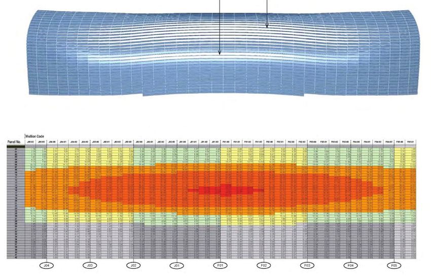
this approach was seen in the calculation of the loads on the structure.
Wind design loads from wind-tunnel tests act over the surface of the
structure and the exact shape of the geometry has a significant effect on the
loads applied to each structural member, dependant on angle and effective-
width. By incorporating the application of wind-loads into the parametric
process, each of the 20 basic load cases and 70 load combinations could be
automatically calculated and applied to each of the 3500 analysis elements.
Without structural analysis being included within the parametric model
framework, fewer analyses would have been possible within the project
programme and inevitably, conservative assumptions would have had to have
been made which would have led to a less optimised and less efficient
design. The extension of GC to bring structural analysis into the family of
parametric modelling tools facilitated a more collaborative approach to
design. The repercussions of architectural design decisions in terms of
structural requirements could be quickly assessed by the engineering team
and fed back to the architectural team. This allowed each discipline to
respond quickly to the others requirements and a truly holistic design
solution was achieved.
4. CLADDING DESIGN
The starting point for the cladding design was also the radial grid array of
sections (Figure 3g) that define the envelope geometry. Further
intermediate sections (Figure 3i) were required to define mullions to
support the cladding between structural bays. Each structural bay was
divided into three, four or five cladding-bays depending on the bay’s
structural lacing of the edge truss. The cladding system was designed as a
rain screen consisting of inter-locking louvers (Figure 7). Panels were planar
Aviva Stadium: A parametric success 175and made from folded polycarbonate sheets; all panels used the same profile
but varied in length. A lateral axis of rotation allowed panels to be fixed in a
range of positions between open and closed (Figure 8). This allowed
sections of the facade to be open to allow air intake and exhaust for air
handling units positioned behind the facade within plant space plenums. The
polycarbonate panel was fixed onto an axle along its own lateral axis.This
axle was supported at either end by a bracket which was connected to a
mullion.The brackets had two axes of rotation; the angles if which were
defined by the positions of neighbouring panels (Figures 9 & 10).
In order to control the openness of panels on the facade a control
strategy was developed that mapped the rotation (opening angle) of each
panel from a cell in an Excel spreadsheet onto the facade. In this way an
abstract elevation was visible in Excel that allowed the locations of air
handling plenums to be specified on the facade. In these areas, panels would
be open to allow air intake and exhaust. Surrounding these open areas,
functions were written in Excel to feather the open angles back to a closed
position, creating smooth transitions between the open and closed areas
(Figure 11). Parametric modelling of the entire facade provided a means for
checking that Populous’ proposed cladding system would work correctly
around the entire stadium envelope and also provided a high level of
architectural control.The parametric model was also used to produce
geometry files for three-dimensional visualisation both in computer
generated graphics (Figure 7) and physical models (Figure 12).
Figure 7: Proposed facade, elevation
and detail.
Figure 8: Panel rotation axis.
176 Paul Shepherd, Roly Hudson and David Hines Figure 9: bracket rotation detail.
Figure 10: Bracket rotation
principle.
Figure 11: Control of panel rotation.
Aviva Stadium: A parametric success 177 Figure 12: Physical model.
4.1. Construction documentation
The parametric modelling of the facade cladding system required the
calculation of all the parameters for configuring rotation angles of panels
and brackets and spacing along mullions. Initially this information was not
represented in any way other than in the model geometry. In order to
document the facade, this numeric information was extracted from the
model and recorded in spreadsheets. Together with geometric models, this
information was required as part of the construction documentation
package (Figure 13).This was issued in a form that allowed a subcontractor
to recreate the facade geometry.The data format was developed by closely
collaborating with facade subcontractors.
The geometric principles of the facade system were discussed and the
content and format of issued information agreed. Based on this, the
architectural parametric model was extended to incorporate these
requirements. In addition to the numeric information calculated to construct
the parametric model, the subcontractors required all panel lengths and two
further angles for checking construction tolerances. The facade was divided
into sections which were determined by the construction sequence and the
radial grid bays.The contractual purpose of issuing construction
documentation was to express the architectural design intent and provide
enough information to completely reconstruct the system.The
subcontractors would then take full responsibility for the detail design and
co-ordination of the facade with the knowledge that they had modelled it
completely independently. However, in this case the subcontractors chose to
use the parametric architectural geometry issued by Populous as the basis
for their detailed model of the facade system, thus eliminating any possible
discrepancies between desired and as-built geometry.
178 Paul Shepherd, Roly Hudson and David Hines Figure 13: Information issued for
one facade bay.
5. DEVELOPING A COORDINATED
CONSTRUCTION MODEL
Detailed fabrication models were produced by the cladding subcontractor
using the facade geometry construction documentation described above.
Using Dassault Systems’ Solid Works, scripts were created to position each
element of the facade into a construction model. Key details were
developed collaboratively by the architects and the subcontractor. Primary
setting out geometry had been established by the architects, this provided
the means to co-ordinate between the cladding subcontractor, main
contractor and other subcontractors. Detail design decisions could be made
by combining the architect’s model and with connection geometry proposed
by the subcontractors in order to obtain architectural design approval.The
reuse of the same geometric model to coordinated subcontractor’s work
emphasized the importance of the format used by all involved. Populous and
the main contractor defined this format and maintained control of the
model by establishing key setout geometry and the criteria which all parties
adhered to.The difficulty of storing all three-dimensional information from
all sub consultants in a single model was amplified by the range of three-
dimensional platforms used. However the lightweight setting out system
used here was a wireframe model combined with simple written criteria.
This model enabled all parties to develop full construction models within
their own platform to the level of detail they require for production.
6. MANUFACTURE
Having constructed a fully detailed fabrication model, the cladding
subcontractor undertook a process of extracting data sheets and drawings
for production and assembly. The cladding system was designed in such a
way that the parts could all be manufactured and assembled on the factory
Aviva Stadium: A parametric success 179floor or erected into place and connected at height on site in sequence
(Figure 14).The mullions were subdivided into extrudable lengths and
ordered. The brackets and restraint connections were all cast in foundries,
powder coated and shipped to Dublin. The linear sheets of polycarbonate
panels were ordered pre-cut to varying lengths, folded and delivered to
Dublin. In the subcontractor’s factory each assemblage of facade panel was
preassembled and packed in reverse order for unloading and hoisting into
position on site. Each mullion was laid onto a rigging table and drilled in
position to accept the brackets and restraint connections for each part.
This part of the process used drawings extracted directly from the
fabrication model to define the position and rotation of each drill point.
Figure 15 shows a typical mullion drill drawing and the drill rig being moved
along the mullion body can be seen in figure 16. Numbering, panel
sequencing and bar-coding was all extracted from the fabrication model and
used to label all parts assembled in and leaving the factory floor. In parallel,
the steel subcontractor underwent a similar process of offsite fabrication of
parts and shipping of elements to site.The steel was all manufactured in
Italy, packed and delivered by freight to Dublin.
Figure 14: Assembly on site.
180 Paul Shepherd, Roly Hudson and David Hines Figure 15:Typical mullion drill
drawing.
Figure 16: Drill rig being moved
along the mullion body.
Aviva Stadium: A parametric success 1817. CONSTRUCTION
Much of the assembly work was completed off site and the construction
operation for both the roof and facade was a sequence of connect and
erect. The main steel work was assembled inside the stadium and erected
into position (Figure 17). Bolted connection details allowed major parts to
be assembled, lifted and connected in position.This was done in sequence
using a series of temporary towers to aid the support of the roof’s main
truss until the structure was completed (Figure 18).The cladding assembly
closely followed the steel erection. Once the edge truss frame was in
position the cladding mullions with all brackets attached were hung top
down in sequence from the roof structure (Figure 19). A cladding panel was
lifted onto each mullion and fixed into position. Each panel had a
predefined rotation and a pre-drilled and positioned support arm. This
meant there was no need for measuring onsite to position parts. In this
way any errors could be identified and corrected in the factory and the
primary site concern was control of the erection sequence.
Figure 17: Erection of steel work.
182 Paul Shepherd, Roly Hudson and David Hines Figure 18: Propped structure.
Figure 19: Installing facade mullions.
Aviva Stadium: A parametric success 1838. CONCLUSIONS
This paper documents the design and construction of the Aviva Stadium
Dublin, which used an integrated parametric model across the design
disciplines. This novel and innovative approach had many advantages.
The structural engineering team benefitted from having a parametric
model built on top of that created by the architects. It allowed them to
respond immediately to changes in the overall shape of the stadium without
having to spend time rebuilding structural and analytical models to reflect
the new geometry, as is typically the case. This meant that the architects
could quickly get feedback on the structural implications of their design
decisions and a more optimal overall design was possible.
The extra time required to create the link between parametric model
and analysis was also a good investment. Without it, the analysis would lag
behind the design, since the loading used for analysis would have to be
conservatively based on approximate bay-widths and member sizes. By
having a parametric analysis model, a much more accurate representation of
the loads was used at all times with no extra effort, leading to a better
understanding of the structural behaviour and a more efficient design.
The process undertaken by the architects was to use a single parametric
model as both a design tool and a coordination platform. This model was also
a key asset in the manufacture and construction process. It allowed a clear
sequence of events from the design of the project in conceptual stages
through to completion. This clear process enabled management of the
intricacies of coordinating building trades associated with such a complex
construction. The process placed the architect firmly in control of the project
and allowed a complex building framework to be precisely established.
The concept of using a single parametric model across a multi-
disciplinary team, and sharing data intelligently with engineering analysis
software and manufacturing processes has led to an efficient and inspiring
design. This success has been recognized through the long list of
construction industry awards bestowed on the project team, including the
Irish Concrete Society’s Overall Award and Best Building Award 2011, RIAI’s
Best Leisure Building 2011 and RIBA’s Architectural Excellence (EU) 2011.
Since the completion of the Aviva Stadium design, other CAD software
vendors have begun to include parametric modelling capabilities in their
standard off-the-shelf products, the use of which is fast becoming the norm.
However, it is not until these models are shared amongst all members of
the design team as a matter of course, and engineering analysis applications
are fully integrated, that the true benefits of a parametric approach to
building design can be realised.
Acknowledgements
The authors wish to acknowledge the support of Populous and Buro
Happold.
184 Paul Shepherd, Roly Hudson and David HinesReferences
1. Hudson, R, Strategies for parametric design in architecture, PhD Thesis, University of
Bath, Bath, 2009.
2 Shepherd, P., Aviva Stadium – the use of parametric modelling in structural
design, The Structural Engineer, 2011, 89(3), 28-34.
3. Hudson, R, Knowledge acquisition and parametric model development,
International Journal of Architectural Computing, 2008, 6(4), 435-451.
4. Shepherd, P and Hudson, R, Parametric definition of Lansdowne road stadium, in
Shell and Spatial Structures: Structural Architecture – Towards the future looking to the
past, IASS,Venice, Italy, 2007, paper 157.
5. Lindsey, B., Digital Gehry. Birkhauser Verlag, 2002.
6. Williams, C. J. K.,The analytical and numerical definition of the geometry of the
British Museum Great Court Roof, in Burry, M., Datta, S., Dawson & A. J. (eds),
Mathematics & Design, 2001, 434-440.
Paul Shepherd1, Roly Hudson2 and David Hines3
1University of Bath, UK
p.shepherd@bath.ac.uk
2Dalhousie University, Canada
r.hudson@dal.ca
3Populous, UK
Aviva Stadium: A parametric success 185You can also read