Nano Energy - Zhong Lin Wang
←
→
Page content transcription
If your browser does not render page correctly, please read the page content below
Nano Energy 89 (2021) 106335
Contents lists available at ScienceDirect
Nano Energy
journal homepage: www.elsevier.com/locate/nanoen
Universal equivalent circuit model and verification of current source for
triboelectric nanogenerator
Da Zhao a, b, 1, Xin Yu a, 1, Zhenjie Wang a, Jianlong Wang a, b, Xiang Li a, Zhong Lin Wang a, c, d, *,
Tinghai Cheng a, b, c, *
a
Beijing Institute of Nanoenergy and Nanosystems, Chinese Academy of Sciences, Beijing 101400, China
b
School of Mechatronic Engineering, Changchun University of Technology, Changchun, Jilin 130012, China
c
CUSTech Institute, Wenzhou, Zhejiang 325024, China
d
School of Materials Science and Engineering, Georgia Institute of Technology, Atlanta, GA 30332-0245, USA
A R T I C L E I N F O A B S T R A C T
Keywords: In the field of energy harvesting and self-powered sensing, the universal equivalent circuit model of triboelectric
Triboelectric nanogenerator nanogenerators (TENGs) is an important development tool for research and applications. Such a universal model
Current source of the current source is established to first order for the basic operating modes of a TENG, which provide the
Universal equivalent circuit model
related theoretical models and electrical models used in simulation. The universal first-order equivalent circuit
Experiment verification
Carrying capacity
model demonstrates that the carrying capacity of a TENG separates into three regions of distinct output char
acteristics, namely, constant current, maximum power, and constant voltage. Moreover, employing electrome
ters, an electrometer and multimeters, and TENGs in series and parallel in successive experiments, we verify that
the TENG can be considered a current source with a resistance of mega-ohms and a capacitance of nano-farads.
Overall, our first-order model sets electrical standards for the internal circuit of the TENG and therefore provides
theoretical guidance that lays the foundation for applications in high-performance supply and grid-connected
power generation.
by comparing electromagnetic power generation methods, the TENG
1. Introduction can be considered a constant current source with a large internal resis
tance [30–32]. The research hints at the electrical mechanism of the
In 2012, Wang’s group [1] first proposed the triboelectric nano TENG being important [33–35] and its equivalent circuit model being
generator (TENG) that converted widely distributed mechanical energy central in the theoretical assessments of the output performance and
into electrical energy [2–5]. There are four distinct working modes engineering applications for grid-connected power generation [36–38].
classified by their operation: two normal modes of motion, called Therefore, analyzing the internal circuit, evaluating the power source,
contact-separation (C-S) [6,7] and single-electrode (S-E) [8,9], and two and establishing a more explicit and universal first-order equivalent
tangential modes of motion, called lateral-sliding (L-S) [10,11] and circuit model (FO-ECM) of the TENG is essential [39–41].
free-standing (F-S) [12,13]. Because TENGs can be made of various Hence, a universal FO-ECM of the current source is established by
materials and display good low-frequency characteristics, they have analyzing the working output of the various operating modes of the
significant value in research and applications as micro/nano power TENG. This model was verified in simulations of the theoretical model
sources and self-powered sensing, as well as blue energy and and the electronic circuit. The carrying capacity of the TENG was found
high-voltage sources [14–18]. to separate into three regions. A detailed experimental verification was
As is known to all, theory and applications of TENGs have progressed conducted from measurements taken in experiments using separately
with further research [19–23] that has deepened the understanding of electrometers, an electrometer and multimeters, and TENGs both in
their mechanism [24–27]. Indeed, when a TENG uses a bridge rectifier series and in parallel. With its verification, the FO-ECM sets electrical
to charge a capacitance, its operation is equivalent to a direct-current standards for the internal circuits of the TENG and provides valuable
voltage source with a constant internal resistance [28,29]. Moreover, guidance on reactance matching that is pertinent for theoretical
* Corresponding authors at: Beijing Institute of Nanoenergy and Nanosystems, Chinese Academy of Sciences, Beijing 101400, China.
E-mail addresses: zhong.wang@mse.gatech.edu (Z.L. Wang), chengtinghai@binn.cas.cn (T. Cheng).
1
These authors contributed equally to this work.
https://doi.org/10.1016/j.nanoen.2021.106335
Received 17 June 2021; Received in revised form 6 July 2021; Accepted 11 July 2021
Available online 15 July 2021
2211-2855/© 2021 Elsevier Ltd. All rights reserved.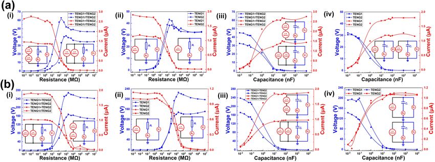
D. Zhao et al. Nano Energy 89 (2021) 106335
Nomenclature + series connection
AC alternating current
FO-ECM the first-order equivalent circuit model I0 current in the current source model
C-S mode contact-separation mode R0 internal resistance
L-S mode lateral-sliding mode C0 internal capacitance
S-E mode single-electrode mode I1 current of the outer branch
F-S mode free-standing mode IR0 current of internal resistance
CC-OCR constant current output characteristic region VR0 load voltage of R0
MP-OCR maximum power output characteristic region RL load resistance
CV-OCR constant voltage output characteristic region VRL load voltage of RL
VA voltage measured by electrometer ZR equivalent impedance of RL
VB voltage measured by multimeter f frequency of AC
AA current measured by electrometer Voc open-circuit voltage
ZL external branch load impedance Isc short-circuit current
// parallel connection
developments and practical applications of the TENG. the TENG acts as a variable capacitor.
The equivalent circuit model of the TENG is established from
2. Theory and simulation analysis Kirchoff’s current law at the junctions; that is, the internal current I0 is
the sum of the current of the internal resistor IR0 and the current I1 in the
2.1. Model establishment outer branch connecting the load,
I0 = I1 + IR0 (1)
TENGs operate in four basic working modes (Fig. 1a–d), each of
which can be prescribed a FO-ECM (Fig. 1e) based on their electrical Applying Ohm’s law, with VR0 the internal voltage and R0 the in
characteristics, namely, current I0, internal resistance R0, and internal ternal resistance, Eq. (1) becomes
variable capacitance C0. Here, the resistor is connected in parallel with VR 0
the current source and in series with the capacitor. The TENG is I0 = I1 + (2)
R0
considered a current source because when measuring the devices in
series or in parallel the voltage is divided. The performance of two Given load resistance RL, the equivalent impedance ZR of the outer
TENGs in parallel subsequently improves. Conversely, the performance branch is
of two TENGs in series remains unchanged [23]. Because there is a layer √̅̅̅̅̅̅̅̅̅̅̅̅̅̅̅̅̅̅̅̅̅̅̅̅̅̅̅̅̅̅̅
( )2̅
of non-conductive polymer material between the two electrodes, the ZR = RL +2 1
. (3)
TENG has a large internal resistance. Given the basic working principle 2πfC0
of the TENG, an internal capacitance develops, and during operations,
Fig. 1. Theoretical model of the equivalent circuit for a TENG: (a) contact-separation mode (C-S mode), (b) lateral-sliding mode (L-S mode), (c) single-electrode
mode (S-E mode), and (d) free-standing mode (F-S mode); (e) equivalent circuit model.
2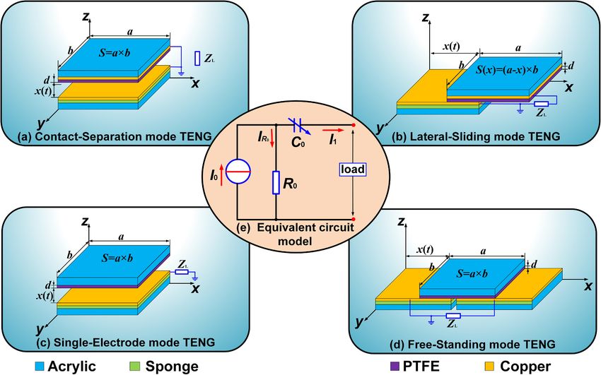
D. Zhao et al. Nano Energy 89 (2021) 106335
Because the voltages of the two branches are equal, we obtain In brief, the output performance of the TENG is directly related to the
√̅̅̅̅̅̅̅̅̅̅̅̅̅̅̅̅̅̅̅̅̅̅̅̅̅̅̅̅̅̅̅
( )2̅ load; load voltage is linearly dependent with load resistance, and the
VR L 1 load current is inversely dependent with load resistance. Therefore,
VR 0 = 2
RL + , (4)
RL 2πfC0 according to the theoretical model, the load resistance establishes three
different regions. When the reactance of the load resistance is greater
where VRL denotes the voltage across the load resistor, and f the fre than the internal capacitance, the load current remains almost constant
quency of the alternating-current signal passing through the internal but is at a low level, whereas the voltage remains almost constant but is
capacitor. Combining Eqs. (2) and (4) yields I0 for the current source at a high level. When the impedance of the load resistor is smaller than
model, internal capacitance and larger than the internal resistance, a change in
⎧ √̅̅̅̅̅̅̅̅̅̅̅̅̅̅̅̅̅̅̅̅̅̅̅̅̅̅̅̅̅̅
( load resistance induces an obvious change in the current on the load
⎪
⎪
⎪
VR L
R2L +
1 2
) branch. Hence, the rate of change in voltage of the load resistor is faster.
⎪
⎪
⎪ V
⎪ RL +
⎪
R L 2 π fC0 When the impedance of the load resistor is smaller than the internal
⎨ , RL ∕
=0
RL R0 resistance and the resistance changes, the current in the load resistor
I0 = (5)
⎪
⎪
⎪
( ) approaches that of the current source. Therefore, the load resistance
⎪ 1
⎪
⎪
⎪ I1 becomes linearly proportional to the load voltage. Conversely, a nega
⎪ 2πf C0
⎩I +
1 , RL = 0 tive correlation develops between load voltage and capacitance, and a
R0
positive correlation develops between load current and load capaci
Here, frequency f can be regarded as the working frequency of TENG. tance. This trend is opposite to that of load resistance.
The load voltage VRL and load current I1 can now be determined from Eq.
(5) in the forms, 2.2. Simulation analysis
VR L =
I0 R0 RL
√̅̅̅̅̅̅̅̅̅̅̅̅̅̅̅̅̅̅̅̅̅̅̅̅̅̅̅̅ (6) Circuit simulations of the FO-ECM were performed (Fig. 2a). The
( )2 ,
2 1
simulation software and related parameter settings are listed in
R0 + RL + 2πfC0 Table S1. The voltage and current curves (Fig. 2b) under different load
resistances and capacitances show that, with increasing resistance, load
I 0 R0 voltage rises and load current decreases, whereas, with increasing
I1 = √̅̅̅̅̅̅̅̅̅̅̅̅̅̅̅̅̅̅̅̅̅̅̅̅̅̅̅̅
)2 . (7)
( capacitance, load voltage falls and load current increases. These load
R0 + R2L + 2π1fC0 curves feature three regions differing in properties regardless of capac
itive or resistive loading. In the first region (Fig. 2b(i)), the current is
These two expressions dictate the open-circuit voltage Voc and short- large and relatively constant, and the voltage rises linearly. In the second
circuit current Isc, region, the load voltage rises rapidly, and the load current drops quickly.
The voltage and current curves intersect here, at which point the load
Voc,RL →+∞ = I0 R0 , (8) power for this TENG reaches a peak. In the third region, the voltage of
TENG approaches the open-circuit voltage and remains almost constant,
2πfC0 R0 I0
Isc,RL =0 = . (9) while the current decreases slowly. For capacitive loading (Fig. 2b(ii)),
2πfC0 R0 + 1
the trend for the curves of load voltage and current are opposite to those
In the theoretical calculations applying our FO-ECM, geometrical for resistive loading (Fig. 2b(i)).
expressions for resistance and capacitance are inserted in Eq. (5) to give
for the internal current, 3. Results and discussion
⎧ √̅̅̅̅̅̅̅̅̅̅̅̅̅̅̅̅̅̅̅̅̅̅̅̅̅̅̅̅̅̅̅̅
( ̅
⎪
⎪
⎪ 2 2kd 2 The experimental measurements for the C-S and L-S modes include
⎪ V S + )
measurements using electrometers, an electrometer and multimeters,
⎪ RL
⎪ VR L
⎪ f εr ε0 RL
⎪
⎨ + =0
, RL ∕
R ρ L and TENGs in series and in parallel. For convenience, the C-S and L-S
I0 = L
(10)
⎪
⎪ (
2kd
) modes were selected for this study. The essential electrometer mea
⎪
⎪
⎪
⎪
⎪
I1 surements and the series-parallel measurements of two TENGs were
⎪ f εr ε0
⎩ I1 + , RL = 0 performed for the other modes.
ρL
where the electrical resistance R0 is related to the cross-sectional area of 3.1. Measurement by electrometers
the resistor S, length L, and resistivity ρ. For parallel plates, the capac
itance C0 is related to the plate area S, relative distance d, relative The voltage and current curves of a TENG in the C-S mode (Fig. 3(a))
permittivity εr, vacuum permittivity ε0, and k is the constant of elec and L-S mode (Fig. 3(b)) were recorded under resistive loading (i) and
trostatic force. capacitive loading (ii) respectively. The voltage and current load curves
Similarly, with load capacitance CL, Eq. (5) yields separate into three regions, similar to the trends obtained in simulations.
We use resistive loading to illustrate the behavior (Fig. 3a(i), b(i)). The
VCL (S + 4επr εkd0 CL ) three regions are classified using the electrical characteristics of the
I0 = 2πfCL VCL + (11)
ρL TENG. The region less than 106 Ω is called the constant-current output
characteristic region (CC-OCR) in which current remains constant, and
where VCL denotes the voltage of load capacitor [see Supporting Infor the voltage tends to increase linearly with increasing load resistance.
mation Note 1, Eqs. (S1–S8)]. The region 106 Ω–109 Ω is called the maximum-power output charac
The maximum values of the internal resistance and the internal teristic region (MP-OCR). With increasing resistance, the current drops
capacitance for the TENG are constant. The output performance of the rapidly, whereas the voltage rises quickly. In this region, voltage and
TENG is related to parameters such as area, thickness, and dielectric current intersect. Being the product of load voltage and current, the
constant that rise in the capacitance and resistance formulae. With the output power peaks at the intersection point. The region above 109 Ω is
TENG’s internal resistance and internal capacitance maintaining values called the constant-voltage output characteristic region (CV-OCR). With
of mega-ohms and nano-farads, respectively, estimates can be derived increasing resistance, voltage remains constant while current decreases
[see Supporting Information Note 1, Eqs. (S9–S12)]. slowly. However, there is a sudden change in resistance at 109 Ω (Fig. 3a
3
D. Zhao et al. Nano Energy 89 (2021) 106335
Fig. 2. Simulation circuits (a) and corresponding loading curves (b) under resistive loading (i) and capacitive loading (ii).
Fig. 3. Voltage and current under different load resistances (i) and capacitances (ii) for contact-separation mode (a, c) and lateral-sliding mode (b, d) obtained from
electrometer measurements. (a) and (b) are single electrometer (A) tests. (c) and (d) are from measurements obtained with two electrometers in parallel.
(i)). The specific waveform is shown in Fig. S1. The TENG of C-S mode is internal capacitor. When the external resistance is less than the internal
a discontinuous contact TENG, and its contact time is very short. The resistance R0, the CC-OCR ensues. When the load resistance and the
charge transfer of TENG is normal when the load is low impedance, and internal resistance are at the same level, the MP-OCR occurs. When the
the waveform is comprehensive. However, when the load is high reactance of the external resistance is greater than the internal capaci
impedance, the charge transfer ability of the TENG decreases, and it can tance, voltage and current curves of the CV-OCR arise. Similar results
not be completely transferred in its working cycle, thus causing the appear for a load capacitor connected in series with the internal
waveform change of the TENG. capacitor when the reactance of the load capacitor is much smaller than
The loading curves of the TENG feature three regions for both the internal resistance. The smaller the capacitance on this branch, the
resistive and capacitive loading. In this situation, the external resistor is greater is the voltage, in accordance with the trend for CC-OCR. In the
connected in parallel with the internal resistor and in series with the same way, the variation in load capacitance was compared with the in-
4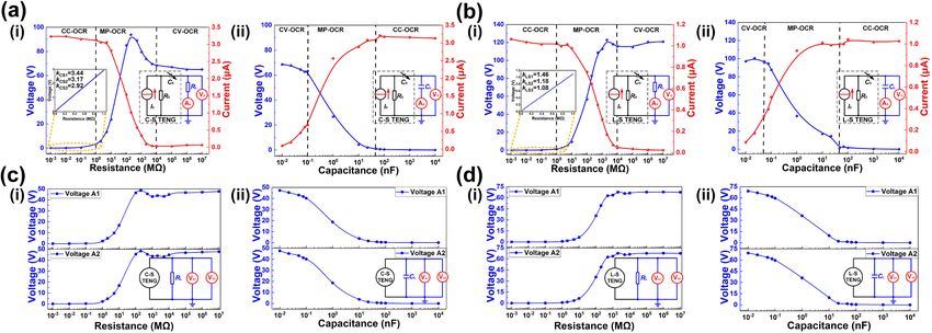
D. Zhao et al. Nano Energy 89 (2021) 106335
series internal variable capacitance in identifying MP-OCR and CV-OCR. are low.
When measuring the performance using two electrometers in sequence, The internal resistance of the electrometer is greater than 200 TΩ,
one is grounded in series and hence no data is acquired. Data can only be and that of the multimeter is 10 MΩ. When the electrometer and the
measured using two electrometers in parallel. The total external load multimeter are connected in series, the load resistance on the test branch
resistance is reduced to half of the original value (Fig. 3c, d). Because the is much larger than the internal resistance. Moreover, the TENG can be
TENG is a current source and the internal resistance of the electrometer considered a constant current source because the amount of charge
is more than 200 TΩ, the performance of the load branch is that of the transferred is constant. That is, the measured value is the open-circuit
third region, therefore the total current of the branch is almost un voltage of the TENG, which is related to the internal resistance of the
changed. When the two electrometers are shunted in parallel, the cur measuring device. Therefore, the electrometer registers a high voltage.
rent flowing through each measurement resistor of each electrometer is When the multimeter is connected in series with the electrometer, the
reduced to half of its original value, so that the voltage measured by each current in the external branch is small and constant. The internal
electrometer is half of its original value. (see Supporting video S1). This resistance of the multimeter is much smaller than the internal resistance
result confirms the correctness of the FO-ECM and further explains why of the electrometer; hence, the voltage registered by the multimeter is
the TENG has output characteristics of a current source. The measured smaller (Fig. 4a(i)).
results for the other modes are consistent with the trends for the C-S and When the electrometer is in parallel with the multimeter and has
L-S modes (in Fig. S2). load ZL, the branch current of the multimeter is relatively small and thus
Supplementary material related to this article can be found online at the electrometer measures a lower voltage (Fig. 4a(iii)). The voltage
doi:10.1016/j.nanoen.2021.106335. displayed by the multimeter depends mainly on the external load. When
the electrometer is registering a current, it is in a short-circuit state. This
situation is equivalent to the multimeter connected in parallel with load
3.2. Hybrid measurements using an electrometer and multimeters
ZL (Fig. 4a(iv)).
Various hybrid connections (Fig. 5a), in which an electrometer is
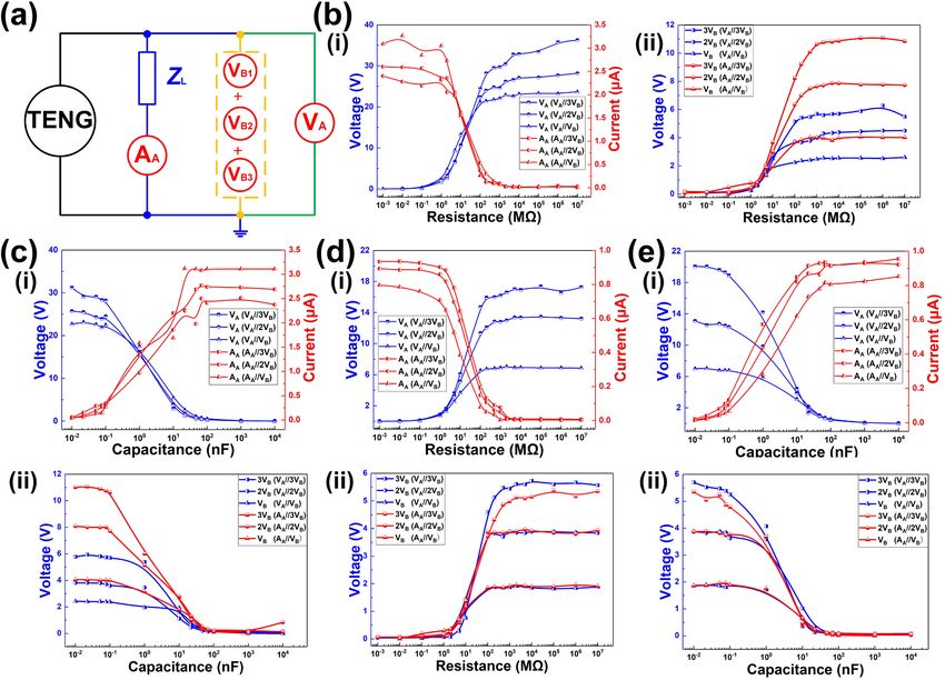
Loading curves of the TENG (Fig. 4) were obtained with a multimeter
connected in parallel with 1–3 multimeters connected in series, were set
and an electrometer connected in series and in parallel. Fig. 4a shows the
up and load voltage and current data were recorded. The best output
test circuits. Fig. 4a(i, ii) show the two measurement devices in series,
performance was registered by the electrometer with three multimeters
although when the current is tested by a multimeter and an electrometer
in series (Fig. 5(i)). With multiple multimeters in series, the resistance of
in series, the internal equipment is short-circuited. The measurement
the branch circuit increases. Therefore, whether the TENG is in the C-S
data is consistent with current data measured using a single electrom
mode (Fig. 5b,c) or L-S mode (Fig. 5d,e), the performance measured by
eter; hence, only an in-series voltage test was conducted. Circuit dia
the electrometer is significantly improved. The load resistance increases
grams with the two devices in parallel are given in Fig. 4a(iii, iv). Fig. 4b
with the number of multimeters. Moreover, the output performance
and c show the voltage and current curves with the TENG in the C-S and
continues to strengthen, proving that the output characteristics of TENG
L-S modes. Both the current and voltage curves were measured using an
are the same as the current source (see Supporting video S2 and S3).
electrometer and multimeter. Voltage values from the electrometer are
That is, the hybrid measurements obtained from the electrometer and
high for the devices in series but are low for devices in parallel. In
multimeters verifies the applicability of the FO-ECM.
addition, when the multimeter and the electrometer are in series (Fig. 4c
Supplementary material related to this article can be found online at
(i)), voltages measured by the electrometer are high, but when they are
doi:10.1016/j.nanoen.2021.106335.
in parallel (Fig. 4c(iii)), the voltage values recorded by the electrometer
Fig. 4. Voltage and current curves for different load resistances (i, iii) and capacitances (ii, iv) as measured by electrometer (A) and multimeter (B) in series (+) and
in parallel (//): (a) test circuits, the TENG in (b) contact-separation and (c) lateral-sliding modes.
5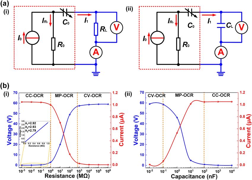
D. Zhao et al.                                                                                                                            Nano Energy 89 (2021) 106335

Fig. 5. Voltage and current curves for different load resistances (b, d) and capacitances (c, e) as well as the hybrid connections of measuring device for electrometer
(A) and multimeter (B). (a) The test circuit for the TENG operating in (b, c) contact-separation mode and (d, e) lateral-sliding mode.

   Supplementary material related to this article can be found online at               respectively. The series and parallel connections of TENG1 and TENG2
doi:10.1016/j.nanoen.2021.106335.                                                      are shown in Fig. 6a(i, iii) and 6b(i, iii). The basic measurements of
                                                                                       TENG1 and TENG2 are shown in Fig. 6a(ii, iv) and b(ii, iv). The test
3.3. Measurement of TENGs in series and parallel                                       circuit for each TENG setup is illustrated as an inset. The trend in load
                                                                                       voltage and current is consistent with previous measurements, which
    The load voltage and current curves were obtained for two TENGs in                 shows that the series/parallel connection of the TENGs conforms to the
series and in parallel (Fig. 6a, b) and operating in the C-S and L-S modes,            basic laws of power supply. More importantly, the performance for

Fig. 6. Voltage and current curves for TENG1 and TENG2 in series (+) and in parallel (//) operating in (a) contact-separation and (b) lateral-sliding modes for
different load resistances (i, ii) and load capacitances (iii, iv).

                                                                                   6
D. Zhao et al. Nano Energy 89 (2021) 106335
TENG1 and TENG2 are not much different from the basic experimental 5.2. Measurement environment
test. The performance is improved for TENG1 and TENG2 in parallel,
and the output performance in series is similar to a single TENG (see During the test, the constant temperature and humidity box (Y-HF-
Supporting video S4). This fact is attributed to the power supply of the 960L, Yuhangzhida, China) are used to control the temperature and
TENG being a current source, and the performance of current sources in humidity. The temperature and relative humidity are maintained at
parallel increases, whereas the performance for a series setup is equal to 25 ℃ and 45%, respectively. A two-phase hybrid servo motor
that for the maximum current source. In addition, the performance of (DE60HB102-1000, Vimidi, China) drives TENG for experiments, and
two TENGs in parallel is not equal to the sum of that of two TENGs. The the drive frequency is 1 Hz. The force and distance are shown in Figs. S5
main reason is that the internal current source of a TENG is not ideal, and S6, Supporting Information Note 2. For the C-S mode, the moving
and with the capacitance varying the TENG resistance is large. There distance is controlled at 5 mm, and the force sensor (Model 41, Hon
fore, the performance of the TENG depends on the equivalent circuit eywell, USA) is used for force control, and the force is 13.5 N. For the L-S
model. The trends in the load performance for the other modes are mode, the moving distance is 50 mm and a 500 g weight is used to
shown in Fig. S3. The load voltage and current for a TENG operating in pressurize. The force is 9.77 N. In addition, for the L-S mode, the force of
the S-E and F-S modes are consistent with the C-S and L-S modes, which TENG can be changed by adding weights.
show that the FO-ECM well describes the four basic operating modes.
Moreover, the series/parallel setups for two TENGs demonstrate the 5.3. Device of measurement
reliability of the FO-ECM.
Supplementary material related to this article can be found online at The output signal is collected by an electrometer (6514, Keithley,
doi:10.1016/j.nanoen.2021.106335. USA) and a multimeter (UT58A, UNI-T, China). The signal of elec
Whether two TENGs are connected either in series or in parallel, the trometer collecting is converted by a data acquisition system (USB-6218,
point of intersection of the current and voltage curves appears at mega- National Instruments, USA). The display and storage of data are per
ohm levels for different resistive loadings and at nano-farad levels for formed by installing the software LabVIEW with the computer. More
different capacitive loadings. Therefore, the TENG’s internal resistance over, all load voltage and current value points are the peak-to-peak
and capacitance are at megaohm and nano-farad levels, respectively. points of the collected waveform in this paper.
That is, the TENG acts as a current source with the FO-ECM being a more
suitable internal circuit model governing the TENG operating principle. CRediT authorship contribution statement
4. Conclusions Da Zhao: Investigation, Writing - original draft, Validation. Xin Yu:
Conceptualization, Investigation, Writing - original draft, Validation.
The universal FO-ECM of the current source was established for the Zhenjie Wang: Investigation, Validation. Jianlong Wang: Investiga
TENG. A theoretical model of the TENG with load voltage was derived in tion, Validation. Xiang Li: Investigation. Zhong Lin Wang: Conceptu
accordance with the FO-ECM. The open-circuit voltage and short-circuit alization, Resources, Writing - review & editing, Supervision. Tinghai
current were obtained; these govern the theoretical relationship be Cheng: Conceptualization, Resources, Writing - review & editing,
tween the TENG and load resistance. Moreover, the behavior of the FO- Supervision.
ECM of the current source were verified in circuit simulations. Model
simulations showed that the carrying capacity features three output Declaration of Competing Interest
characteristic regions: specifically, constant current, maximum power
(in which load current and voltage vary significantly and the maximum The authors declare that they have no known competing financial
power point appears), and constant voltage. Finally, this model was interests or personal relationships that could have appeared to influence
verified using measurement data obtained using in separate experiments the work reported in this paper.
electrometers, an electrometer and multimeters, and two TENGs both in
series and in parallel. The experimental results confirmed that the power Acknowledgements
supply of the TENG is a current source with mega-ohm-level internal
resistance and nano-farad-level internal capacitance. The FO-ECM of the The authors are grateful for the supports received from the National
TENG established an internal circuit standard. Moreover, the model Key R&D Project from the Minister of Science and Technology (Nos.
offers theoretical guidance in reactance matching, laying the foundation 2016YFA0202701 and 2016YFA0202704) and the Beijing Municipal
for further practical applications of TENGs. Science and Technology Commission (No. Z171100002017017).
5. Experimental section Appendix A. Supporting information
5.1. Fabrication of TENG Supplementary data associated with this article can be found in the
online version at doi:10.1016/j.nanoen.2021.106335.
The fabrication materials used in TENG of contact-separation (C-S)
and lateral-sliding (L-S) modes are polytetrafluoroethylene (PTFE, References
thickness of 80 µm) and copper electrodes (thickness of 65 µm). The
electrode form of TENG is shown in Fig. S4. For the single-electrode (S- [1] F.R. Fan, Z.Q. Tian, Z.L. Wang, Flexible triboelectric generator, Nano Energy 1 (2)
E) and free-standing (F-S) modes, a single circular TENG is used in the (2012) 328–334, https://doi.org/10.1016/j.nanoen.2012.01.004.
[2] B. Chen, Y. Yang, Z.L. Wang, Scavenging wind energy by triboelectric
series-parallel experiment of the test device. The diameter of the circle nanogenerators, Adv. Energy Mater. 8 (10) (2018), 1702649, https://doi.org/
electrode is 50 mm and 70 mm, respectively. When both TENGs are 10.1002/aenm.201702649.
connected in series and parallel, the circular electrode is divided into [3] C. Ye, K. Dong, J. An, J. Yi, Z.L. Wang, A triboelectric–electromagnetic hybrid
nanogenerator with broadband working range for wind energy harvesting and a
two semicircular electrodes to ensure the same frequency of the 2 TENGs
self-powered wind speed sensor, ACS Energy Lett. 6 (2021) 1443–1452, https://
(Fig. S4a, c). For the L-S and F-S mode, square electrodes are used, and doi.org/10.1021/acsenergylett.1c00244.
the length and width are 70 × 50 mm2 and 40 × 40 mm2, respectively. [4] L. Xu, T. Jiang, P. Lin, J.J. Shao, C. He, W. Zhong, X.Y. Chen, Z.L. Wang, Coupled
Only a single TENG is used for measurement in the series and parallel triboelectric nanogenerator networks for efficient water wave energy harvesting,
ACS Nano 12 (2) (2018) 1849–1858, https://doi.org/10.1021/acsnano.7b08674.
experiment of the measurement device. When two TENGs in series or [5] M. Yin, X.H. Lu, G.D. Qiao, Y.H. Xu, Y.Q. Wang, T.H. Cheng, Z.L. Wang, Mechanical
parallel, two TENGs are used for measurement (Fig. S4b, d). regulation triboelectric nanogenerator with controllable output performance for
7
D. Zhao et al. Nano Energy 89 (2021) 106335
random energy harvesting, Adv. Energy Mater. 10 (22) (2020) 8899, https://doi. [29] S.M. Niu, S.H. Wang, L. Lin, Y. Liu, Y.S. Zhou, Y. Hu, Z.L. Wang, Theoretical study
org/10.1002/aenm.202000627. of contact-mode triboelectric nanogenerators as an effective power source, Energy
[6] L. Cheng, Q. Xu, Y.B. Zheng, X.F. Jia, Yong Qin, A self-improving triboelectric Environ. Sci. 6 (2013) 3576–3583, https://doi.org/10.1039/C3EE42571A.
nanogenerator with improved charge density and increased charge accumulation [30] F.R. Fan, W. Tang, Y. Yao, J.J. Luo, C. Zhang, Z.L. Wang, Complementary power
speed, Nat. Commun. 9 (2018) 3773, https://doi.org/10.1038/s41467-018-06045- output characteristics of electromagnetic generators and triboelectric generators,
z. Nanotechnology 25 (2014), 135402, https://doi.org/10.1088/0957-4484/25/13/
[7] R.D.I.G. Dharmasena, K.D.G.I. Jayawardena, C.A. Mills, J.H.B. Deane, J.V. Anguita, 135402.
R.A. Dorey, S.R.P. Silva, Triboelectric nanogenerators: providing a fundamental [31] N. Zhang, C. Qin, T.X. Feng, J. Li, Z.R. Yang, X.P. Sun, E.J. Liang, Y.C. Mao, X.
framework, Energy Environ. Sci. 10 (2017) 1801–1811, https://doi.org/10.1039/ D. Wang, Non-contact cylindrical rotating triboelectric nanogenerator for
C7EE01139C. harvesting kinetic energy from hydraulics, Nano Res. 13 (2020) 1903–1907,
[8] X.Y. Chen, Y.L. Wu, J.J. Shao, T. Jiang, A.F. Yu, L. Xu, Z.L. Wang, On-skin https://doi.org/10.1007/s12274-020-2654-7.
triboelectric nanogenerator and self-powered sensor with ultrathin thickness and [32] X.N. Xia, G.L. Liu, L. Chen, W.L. Li, Y. Xi, H.F. Shi, C.G. Hu, Foldable and portable
high stretchability, Small 13 (2017), 1702929, https://doi.org/10.1002/ triboelectric-electromagnetic generator for scavenging motion energy and as a
smll.201702929. sensitive gas flow sensor for detecting breath personality, Nanotechnology 26
[9] F. Zhan, A.C. Wang, L. Xu, S.Q. Lin, J.J. Shao, X.Y. Chen, Z.L. Wang, Electron (2015), 475402, https://doi.org/10.1088/0957-4484/26/47/475402.
transfer as a liquid droplet contacting a polymer surface, ACS Nano 14 (2020) [33] C. Zhang, W. Tang, C.B. Han, F.R. Fan, Z.L. Wang, Theoretical comparison,
17565–17573, https://doi.org/10.1021/acsnano.0c08332. equivalent transformation, and conjunction operations of electromagnetic
[10] J.J. Shao, T. Jiang, W. Tang, X.Y. Chen, L. Xu, Z.L. Wang, Structural figure-of- induction generator and triboelectric nanogenerator for harvesting mechanical
merits of triboelectric nanogenerators at powering loads, Nano Energy 51 (2018) energy, Adv. Mater. 26 (22) (2014) 3580–3591, https://doi.org/10.1002/
688–697, https://doi.org/10.1016/j.nanoen.2018.07.032. adma.201400207.
[11] S.M. Niu, Y. Liu, S.H. Wang, L. Lin, Y.S. Zhou, Y.F. Hu, Z.L. Wang, Theory of [34] Y.F. Gu, T.T. Hou, P. Chen, J.X. Cao, C.X. Pan, W.G. Hu, B.R. Yang, X. Pu, Z.
sliding-mode triboelectric nanogenerators, Adv. Mater. 25 (2013) 6184–6193, L. Wang, Self-powered electronic paper with energy supplies and information
https://doi.org/10.1002/adma.201302808. inputs solely from mechanical motions, Photonics Res. 8 (9) (2020) 1496–1505,
[12] S.H. Wang, Y.N. Xie, S.M. Niu, L. Lin, Z.L. Wang, Freestanding triboelectric-layer- https://doi.org/10.1364/PRJ.394044.
based nanogenerators for harvesting energy from a moving object or human [35] T. Guo, J.Q. Zhao, W.B. Liu, G.X. Liu, Y.K. Pang, T.Z. Bu, F.B. Xi, C. Zhang, X.J. Li,
motion in contact and non-contact modes, Adv. Mater. 26 (2014) 2818–2824, Self-powered hall vehicle sensors based on triboelectric nanogenerators, Adv.
https://doi.org/10.1002/adma.201305303. Mater. Technol. 3 (8) (2018), 1800140, https://doi.org/10.1002/
[13] S.M. Niu, Y. Liu, X.Y. Chen, S.H. Wang, Y.S. Zhou, L. Lin, Y.N. Xie, Z.L. Wang, admt.201800140.
Theory of freestanding triboelectric- layer-based nanogenerators, Nano Energy 12 [36] Y.K. Pang, Y.T. Cao, M. Derakhshani, Y.H. Fang, Z.L. Wang, C.Y. Cao, Hybrid
(2015) 760–774, https://doi.org/10.1016/j.nanoen.2015.01.013. energy-harvesting systems based on triboelectric nanogenerators, Matter 4 (1)
[14] W.H. Xu, H.X. Zheng, Y. Liu, X.F. Zhou, C. Zhang, Y.X. Song, X. Deng, M. Leung, Z. (2021) 116–143, https://doi.org/10.1016/j.matt.2020.10.018.
B. Yang, R.X. Xu, Z.L. Wang, X.C. Zeng, Z.K. Wang, A droplet-based electricity [37] X.D. Yang, L. Xu, P. Lin, W. Zhong, Y. Bai, J.J. Luo, J. Chen, Z.L. Wang,
generator with high instantaneous power density, Nature 578 (2020) 392–396, Macroscopic self-assembly network of encapsulated high-performance triboelectric
https://doi.org/10.1038/s41586-020-1985-6. nanogenerators for water wave energy harvesting, Nano Energy 60 (2019)
[15] C. Zhang, J.K. Chen, W.P. Xuan, S.Y. Huang, B. You, W.J. Li, L.L. Sun, H. Jin, X. 404–412, https://doi.org/10.1016/j.nanoen.2019.03.054.
Z. Wang, S.R. Dong, J.K. Luo, A.J. Flewitt, Z.L. Wang, Conjunction of triboelectric [38] W.Y. Shang, G.Q. Gu, W.H. Zhang, H.C. Luo, T.Y. Wang, B. Zhang, J.M. Guo, P. Cui,
nanogenerator with induction coils as wireless power sources and self-powered F. Yang, G. Cheng, Z.L. Du, Rotational pulsed triboelectric nanogenerators
wireless sensors, Nat. Commun. 11 (1) (2020) 58, https://doi.org/10.1038/ integrated with synchronously triggered mechanical switches for high efficiency
s41467-019-13653-w. self-powered systems, Nano Energy 82 (2021), 105725, https://doi.org/10.1016/j.
[16] Z.L. Wang, T. Jiang, L. Xu, Toward the blue energy dream by triboelectric nanoen.2020.105725.
nanogenerator networks, Nano Energy 39 (2017) 9–23, https://doi.org/10.1016/j. [39] Z. Wang, W.L. Liu, W.C. He, H.Y. Guo, L. Long, Y. Xi, X. Wang, A.P. Liu, C.G. Hu,
nanoen.2017.06.035. Ultrahigh electricity generation from low-frequency mechanical energy by efficient
[17] R. Lei, Y.X. Shi, Y.F. Ding, J.H. Nie, S.Y. Li, F. Wang, H. Zhai, X.Y. Chen, Z.L. Wang, energy management, Joule 5 (2) (2021) 441–455, https://doi.org/10.1016/j.
Sustainable high-voltage source based on triboelectric nanogenerator with a charge joule.2020.12.023.
accumulation strategy, Energy Environ. Sci. 13 (2020) 2178–2190, https://doi. [40] X. Liang, Z.R. Liu, Y.W. Feng, J.J. Han, L.L. Li, J. An, P.F. Chen, T. Jiang, Z.
org/10.1039/D0EE01236J. L. Wang, Spherical triboelectric nanogenerator based on spring-assisted swing
[18] Z.L. Wang, Triboelectric nanogenerator (TENG)—sparking an energy and sensor structure for effective water wave energy harvesting, Nano Energy 83 (2021),
revolution, Adv. Energy Mater. 10 (17) (2020), 2000137, https://doi.org/ 105836, https://doi.org/10.1016/j.nanoen.2021.105836.
10.1002/aenm.202000137. [41] M. Wang, J.H. Zhang, Y.J. Tang, J. Li, B.S. Zhang, E.J. Liang, Y.C. Mao, X.D. Wang,
[19] Z.L. Wang, On the first principle theory of nanogenerators from Maxwell’s Air-flow-driven triboelectric nanogenerators for self-powered real-time respiratory
equations, Nano Energy 68 (2020), 104272, https://doi.org/10.1016/j. monitoring, ACS Nano 12 (2018) 6156–6162, https://doi.org/10.1021/
nanoen.2019.104272. acsnano.8b02562.
[20] Y. Liu, S.M. Niu, Z.L. Wang, Theory of tribotronics, Adv. Electron. Mater. 1 (9)
(2015), 1500124, https://doi.org/10.1002/aelm.201500124.
[21] Z.L. Wang, On Maxwell’s displacement current for energy and sensors: the origin of
nanogenerators, Mater. Today 20 (2) (2017) 74–82, https://doi.org/10.1016/j. Da Zhao was born in Shandong province, China, in 1994. He
mattod.2016.12.001. received the M.S. degree from Changchun University of Tech
[22] S.M. Niu, S.H. Wang, Y. Liu, Y.S. Zhou, L. Lin, Y.F. Hu, K.C. Pradela, Z.L. Wang, nology, China, in 2020. He is currently studying for his Ph.D.
A theoretical study of grating structured triboelectric nanogenerators, Energy degree in School of Mechatronic Engineering at Changchun
University of Technology. He is focused on triboelectric
Environ. Sci. 7 (2014) 2339–2349, https://doi.org/10.1039/C4EE00498A.
[23] W.H. Zhang, G.Q. Gu, H.F. Qin, S.M. Li, W.Y. Shang, T.Y. Wang, B. Zhang, P. Cui, J. nanogenerators and piezoelectric energy harvester.
M. Guo, F. Yang, G. Cheng, Z. Du, Measuring the actual voltage of a triboelectric
nanogenerator using the non-grounded method, Nano Energy 77 (2020), 105108,
https://doi.org/10.1016/j.nanoen.2020.105108.
[24] K. Zhao, G.Q. Gu, Y.N. Zhang, B. Zhang, F. Yang, L. Zhao, M.L. Zheng, G. Cheng, Z.
L. Du, The self-powered CO2 gas sensor based on gas discharge induced by
triboelectric nanogenerator, Nano Energy 53 (2018) 898–905, https://doi.org/
10.1016/j.nanoen.2018.09.057.
[25] M.Y. Xu, T.C. Zhao, C. Wang, S.L. Zhang, Z. Li, X.X. Pan, Z.L. Wang, High power
density tower-like triboelectric nanogenerator for harvesting arbitrary directional
water wave energy, ACS Nano 13 (2) (2019) 1932–1939, https://doi.org/10.1021/ Dr. Xin Yu is a visiting scholar in Beijing Institute of Nano
acsnano.8b08274. energy and Nanosystems, Chinese Academy of Sciences,
[26] W.H. Zhang, G.Q. Gu, W.Y. Shang, H.C. Luo, T.Y. Wang, B. Zhang, P. Cui, J.M. Guo, currently. He obtained the B.S. and Ph.D. degrees from College
F. Yang, G. Cheng, Z.L. Du, A general charge compensation strategy for calibrating of Electronic Science and Engineering, Jilin University in 2009
the voltage of a triboelectric nanogenerator measured by a capacitive circuit, Nano and 2014, respectively. He was a visiting scholar in Depart
Energy 86 (2021), 106056, https://doi.org/10.1016/j.nanoen.2021.106056. ment of Electrical and Computer Engineering, Michigan State
[27] H.F. Qin, G.Q. Gu, W.Y. Shang, H.C. Luo, W.H. Zhang, P. Cui, B. Zhang, J.M. Guo, University from 2017 to 2018. His interests are triboelectric
G. Cheng, Z.L. Du, A universal and passive power management circuit with high nanogenerators, infrared gas sensing, and photoelectric
efficiency for pulsed triboelectric nanogenerator, Nano Energy 68 (2020), 104372, detection.
https://doi.org/10.1016/j.nanoen.2019.104372.
[28] S.M. Niu, Y.S. Zhou, S.H. Wang, Y. Liu, L. Lin, Y. Bando, Z.L. Wang, Simulation
method for optimizing the performance of an integrated triboelectric
nanogenerator energy harvesting system, Nano Energy 8 (2014) 150–156, https://
doi.org/10.1016/j.nanoen.2014.05.018.
8
D. Zhao et al. Nano Energy 89 (2021) 106335
Zhenjie Wang was born in Hubei Province, China, in 1998. He Prof. Zhong Lin Wang received his Ph.D. from Arizona State
received a B.E. degree from North China Institute of Science University in physics. He now is the Hightower Chair in Ma
and Technology in Hebei Province, China, in 2019. He is terials Science and Engineering, Regents’ Professor, Engineer
currently studying for a master’s degree in the School of ing Distinguished Professor and Director, Center for
Electrical and Electronic Engineering, Changchun University of Nanostructure Characterization, at Georgia Tech. Dr. Wang has
Technology. His interests are triboelectric nanogenerators, made original and innovative contributions to the synthesis,
infrared gas sensing, and photoelectric detection. discovery, characterization and understanding of fundamental
physical properties of oxide nanobelts and nanowires, as well
as applications of nanowires in energy sciences, electronics,
optoelectronics and biological science. His discovery and
breakthroughs in developing nanogenerators established the
principle and technological road map for harvesting mechani
cal energy from environment and biological systems for powering personal electronics. His
research on self-powered nanosystems has inspired the worldwide effort in academia and
industry for studying energy for micro-nano-systems, which is now a distinct disciplinary
in energy research and future sensor networks. He coined and pioneered the field of pie
Jianlong Wang was born in 1996 Shandong province, majored zotronics and piezophototronics by introducing piezoelectric potential gated charge
in mechanical engineering and received his B.E. degree from transport process in fabricating new electronic and optoelectronic devices. Details can be
Changchun University of Technology. He is currently a master found at: http://www.nanoscience.gatech.edu.
degree candidate under the supervision of Prof. Tinghai Cheng
in the same school. His research interest is in the area of
triboelectric nanogenerators.
Prof. Tinghai Cheng received the B.S., M.S. and Ph.D. degrees
from Harbin Institute of Technology in 2006, 2008 and 2013,
respectively. He was a visiting scholar in the School of Mate
rials Science and Engineering at Georgia Institute of Technol
ogy from 2017 to 2018. Currently, he is a professor of Beijing
Institute of Nanoenergy and Nanosystems, Chinese Academy of
Sciences. His research interests are triboelectric nano
generators, piezoelectric energy harvester, and piezoelectric
actuators.
Xiang Li was born in 1996 Heilongjiang province, majored in
Mechanical Engineering and achieved the B.E. degree from the
Shenyang University of Technology in 2018. Now, he is
studying for a master’s (M.S.) degree in Mechanical Engineer
ing at Shenyang Jianzhu University. His research interest is
environmental energy harvesting through triboelectric
nanogenerators.
9
You can also read


