Code Generation from an Abstract State Machine into Contracted C#
←
→
Page content transcription
If your browser does not render page correctly, please read the page content below
Code Generation from an Abstract State
     Machine into Contracted C#

                           Supervisor:      Joseph R. Kiniry

                           Thesis by:         Asger Jensen

                           Date of birth:         10-11-82

                           Email:              asje@itu.dk

                           Thesis start:          01-12-11

                           Thesis end:            01-06-12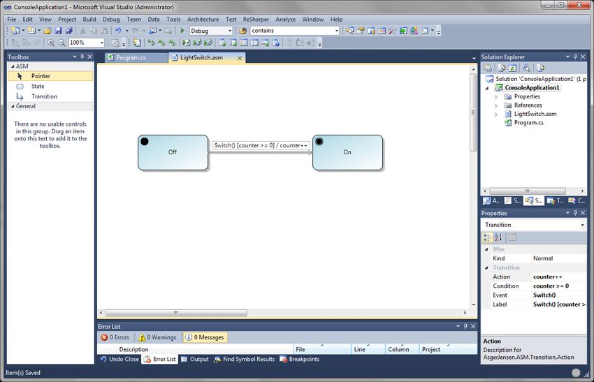
Abstract
In computer science designing systems, whether it is hardware or software, using an abstract state machine
diagram to model the system is a common approach. When using the diagram as a blueprint for
programming, it is possible to lose the equality between the diagram and the actual code, not to mention
the time that was spent creating the code.

Having a tool which generates skeleton code from a state machine is not a new idea. In 2003 Engelbert
Hubbers and Martijn Oostdijk created the AutoJML tool, which derives Java Modeling Language
specifications from UML state diagrams.

The same kind of tool does not exist in the .NET environment. Visual Studio 2010 does offer the possibilities
of creating state machine diagrams, but it is not possible to generate code from the diagram. This thesis is
about creating such a tool, based on Hubbers and Oostdijk work, where the user can create their abstract
state machine diagram and generate contracted skeleton C# code from it.

To accomplice this, a Domain Specific Language has been created, with an added feature to generate code.
The user can create their state machine by adding states and transitions, specify what states should be
initial-, normal- and final state, fill out the transition properties and initiate the validation and generation of
the code. Code Contracts is used in the generated code to keep the constraints of the abstract state
machine diagram.

The result of this thesis is a Visual Studio extension, which makes it possible to get generated contracted C#
code from an abstract state machine diagram.

                                                                                                                 2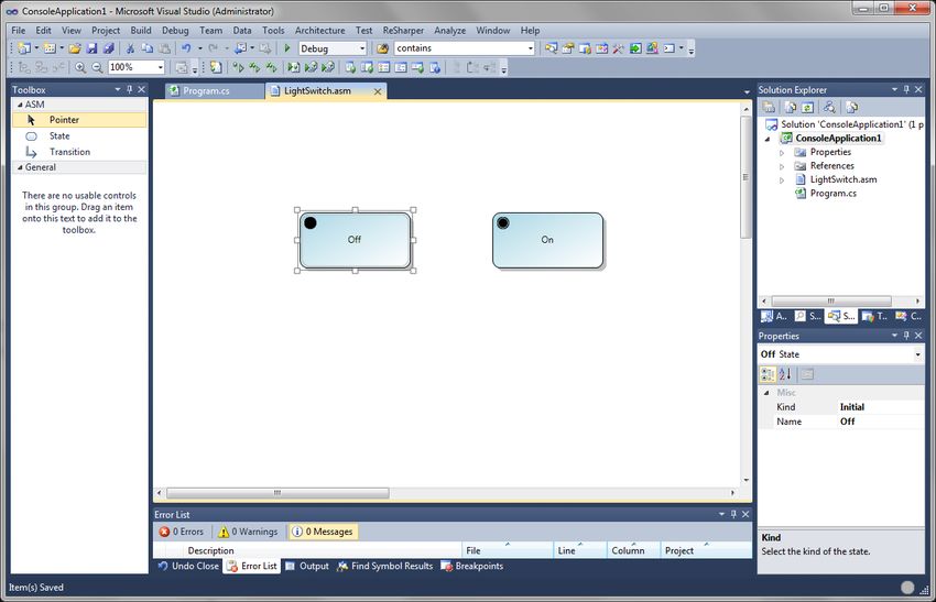
Table of Contents
1       INTRODUCTION .................................................................................................................................................. 5

2       ABSTRACT STATE MACHINES .............................................................................................................................. 5

     2.1        CONTROL STATE ASMS ........................................................................................................................................... 6
     2.2        LINK BETWEEN ASM AND FSM ................................................................................................................................ 6
     2.3        DFA AND NFA DEFINITION ...................................................................................................................................... 7

3       HUBBERS AND OOSTDJIKS PAPER....................................................................................................................... 8

     3.1        THE THESIS COMPARED TO THE PAPER........................................................................................................................ 9

4       THE ASM EXTENSION.........................................................................................................................................10

     4.1        CURRENT FEATURES.............................................................................................................................................. 10
     4.2        FUTURE WORK .................................................................................................................................................... 11

5       EXTENSION WALKTHROUGH .............................................................................................................................11

6       CODE CONTRACTS .............................................................................................................................................14

     6.1        PRECONDITION, POSTCONDITION AND INVARIANT ...................................................................................................... 15
     6.2        ISSUES WITH CODE CONTRACTS AND SOLUTIONS ........................................................................................................ 15

7       BUILDING THE DSL .............................................................................................................................................17

     7.1     THE META-MODEL ............................................................................................................................................... 17
        7.1.1 Embedding and Reference Relations .......................................................................................................... 18
        7.1.2 Allow Duplications ...................................................................................................................................... 19
     7.2     THE GRAPHICAL NOTATION .................................................................................................................................... 20

8       THE BUTTON .....................................................................................................................................................20

     8.1        DECLARING THE BUTTON AND FUNCTIONALITY ........................................................................................................... 20

9       VALIDATION ......................................................................................................................................................21

     9.1        CHOSEN RULES .................................................................................................................................................... 21
     9.2        CONSIDERED RULES .............................................................................................................................................. 22
     9.3        THE CODE ........................................................................................................................................................... 22

10      GENERATING C# CODE.......................................................................................................................................23

     10.1       THE GENERATED CODE .......................................................................................................................................... 24

11      TEST ..................................................................................................................................................................24

     11.1       VALIDATION TEST ................................................................................................................................................. 24
     11.2       GENERATION TEST ................................................................................................................................................ 25

12      CONCLUSION .....................................................................................................................................................26

13      LITERATURE LIST................................................................................................................................................27

14      SOFTWARE ........................................................................................................................................................28

                                                                                                                                                                                     3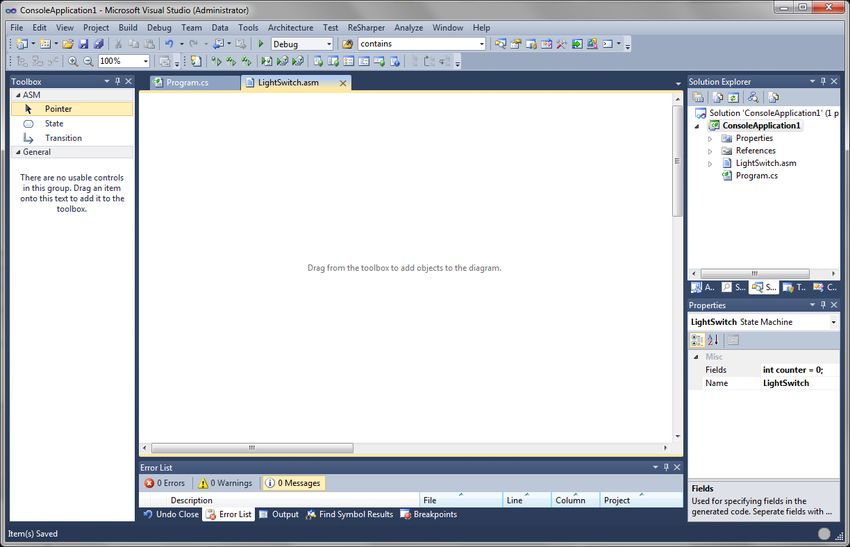
Appendices
APPENDIX A ...............................................................................................................................................................29

APPENDIX B ...............................................................................................................................................................30

APPENDIX C ...............................................................................................................................................................31

APPENDIX D ...............................................................................................................................................................32

APPENDIX E ...............................................................................................................................................................34

APPENDIX F ...............................................................................................................................................................36

APPENDIX G ...............................................................................................................................................................45

APPENDIX H ...............................................................................................................................................................47

                                                                                                                                                                          4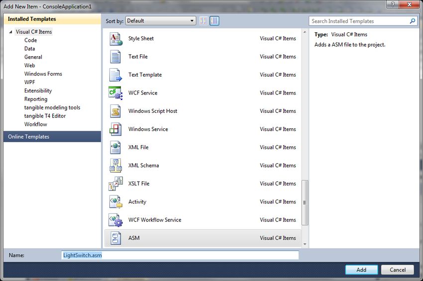
1 Introduction
Over the last 10 years there has been more interest in developing a way of using a state machine model
and generating a skeleton code from it. Engelbert Hubbers and Martijn Oostdijk from the University of
Nijmegen created AutoJML tool which automatically derives Java Modeling Language (JML) specifications
from UML1 state diagrams. This thesis is based on the paper “Generating JML Specifications from UML State
Diagrams” by Engelberg Hubbers and Martijn Oostdijk [1].

A way of achieving the goal of replicating Hubbers and Oostdijk’s earlier experiment in a new programming
language is to define a domain specific language (DSL), where it is possible for users to create an Abstract
State Machine (ASM) diagram. The DSL will also have a functionality to generate code from the created
state machine model, with a validation check of the model before the generation. The final product of the
thesis will be an extension containing the DSL to Visual Studio 2010 (VS2010).

VS2010 does contain a UML Activity Diagram extension to create ASMs it is not possible to generate any
code from the ASM. The possibility to generate skeleton code would boost production speed of software
development considerably. Also one can lose similarity between the ASM and the written code if there is
not a regular comparison, known as architecture drift [8]. So by generating skeleton code from an ASM, one
is sure that the code is equivalent to the ASM.

This report will cover topics, ASMs and how they link to Finite State Machines2 (FSMs), the paper by
Hubbers and Oostdijk, Code Contracts, a use case describing the extension, the meta-model of the
extension, the validation of ASMs, the code generation and the tests of the extension.

2 Abstract State Machines
Designing a system is difficult and can be the most error prone part of the system development [2].
Creating the system requirements is based on what the customer wants, but the customer does not have
the same insight into system design as the developers. This leads to a system description from the
customer that is perhaps incomplete, has misleading details or somewhat ambiguous. The ASM method is
machine- and programming language independent, which makes it a valid method for designing hardware
and software systems. This offers a way for customers and developers to design a system together, which is
precise enough to meet the customer’s wishes, but also abstract enough for the developer’s creative
thinking.

When the customer and developer create an ASM of a system, it is known as a ground model ASM for the
system. The ground model is based on the system description and requirements, and serves as a blueprint
for the project. Since the ground model is created by the customer together with the developer, it can
serve as the basis for the software contract, a documentation which binds the two involved parties.

Having a ground model of the system, it is possible to define a test plan for the system before the actual
coding starts. Furthermore it is also possible to create test cases for the actual ground model, to prevent

1
    Unified Modeling Language
2
    Finite State Machines are also known as Finite Automata (FA)

                                                                                                              5
any major mishaps. These possibilities lower some of the project expenses, since the actual testing is
designed, and some also performed, before the later stages of the development.

The ground model is used as an overview of the entire system, but for the actual development more
specific ASMs are needed. Taking the ground model, a hierarchy of intermediate models can be designed.
The intermediate models, known as stepwise refining ASMs, are a deeper view into the different states in
the ground model ASM. Look at the stepwise refining ASMs as pieces of a bigger puzzle, seen in Fig. 2-1.

                             Fig. 2-1: Stepwise Refining ASMs from a Ground Model ASM

Using the stepwise refining ASMs the individual person responsible for the code has something more
specific to work with, without having to think about the entire system, just the one piece of the puzzle.

2.1 Control State ASMs
In this thesis a version of ASMs called control state ASM is used. The control state machine uses the
notation of the UML activity diagram, together with the structure of FSM to allow the possibility of
manipulating data structures.

The control state ASM contains finitely many control states, which resembles the internal states of FSM.
The states can be used to describe different modes of a system, example shown in Fig. 3-1. As with FSMs,
control state ASMs can be deterministic and non-deterministic. The non-deterministic can be used to
resolve possible conflicting updates of a state.

2.2 Link between ASM and FSM
FSM only holds the states or data structures which is within the boundary of the modeled machine, and
does not contain any variables which can be changed during a transition. The label of the transitions in a

                                                                                                             6
FSM only holds a symbol or a letter from a set of inputs for the FSM, and it is not possible to use arbitrary
expressions as a label. The ASM takes the FSM as a foundation and builds upon it. The ASM has the same
notation of states and transitions, but one can attach variables to the ASM, which can be updated based on
the rules of the transitions. The definition of an ASM [2] is as follows
Basic ASMs are a finite set of so-called transition rules of the form
if Condition then Updates
which transform abstract states…
With the control state ASM used in this thesis a transition has a label with the form
Event( arguments )[ Condition ] /Action
The event is the trigger to update the current state, which can be thought of as a method call with possible
arguments. The condition3 for the transition determines whether or not the transition occurs, and the
action is what is going to happen, if the condition is true. The action can be an exception thrown or a
variable changing value.
2.3 DFA and NFA Definition
As written above, ASMs as well as FSMs can be deterministic and non-deterministic. Deterministic means
that there is one transition from a state for each possible input, whereas the input for a non-deterministic
can lead to one, more than one or no transitions from a state.
Hopcroft et al. [3] defines deterministic as
1. A finite set of states, often denoted with Q
2. A finite set of input symbols, often denoted
3. A transition function that takes as arguments a state and an input symbol and returns a state. The
transition function will commonly be denoted
4. A start state, one of the states in Q
5. A set of final or accepting states F. The set F is a subset of Q
Furthermore Hopcroft et al. defines non-deterministic as
1. Q is a finite set of states
2. is a finite set of input symbols
3. q0, a member of Q, is the start state
4. F, a subset of Q, is the set of final (or accepting) states
5. , the transitions function is a function that takes a state in Q and an input symbol from as
arguments and returns a subset of Q. Notice that the only difference between NFA4 and DFA5is in
3
A condition in an ASM is also known as a guard
4
Non-deterministic Finite Automata a.k.a. Non-deterministic State Machine
5
Deterministic Finite Automata a.k.a. Deterministic State Machine
7the type of value the returns: a set of states in the case of an NFA and a single state in the case of
a DFA
These definitions will be used to build the arguments for the class that generates the skeleton C# code from
the ASM. This will be addressed in section 10.
3 Hubbers and Oostdjiks Paper
Hubbers and Oostdijk created a prototype tool, AutoJML, which automatically derives JML specifications
from UML state diagrams.
The AutoJML tool accepts UML state diagrams as input and generates skeleton Java code with JML
specifications. The JML adds the invariants, pre- and postconditions for each method, class wide. Using the
generated code the software engineer still has to create the actual program, but the program can be
verified against the generated specification.
Hubbers and Oostdijk use the following state diagram, Fig. 3-1, as an example to test their tool with.
Fig. 3-1: GSM authentication state diagram
The example is taken from the world of the Global System for Mobile communication (GSM). Hubbers and
Oostdijk describe the example as follows:
“GSM uses a cryptographic protocol to authenticate the Subscriber Identity Module (SIM), which is
embedded in the cell phone, to the network service provider…
… On a more concrete level the standard describes the protocol using two commands which can be
sent to the SIM: RUN_GSM_ALGORITHM and GET_RESPONSE. The key KI is a 16-byte number stored
in the SIM, the challenge RAND is a 16-byte number sent to the SIM in the data field of the byte
sequence representing the RUN_GSM_ALGORITHM command. The response (SRES, KC), a 12-byte
number (4 for SRES, 8 for KC) is the result of running the Comp128 algorithm with key KI and input
8RAND. This is sent back in the data field of the response byte sequence after sending the
GET_RESPONSE command. The RUN_GSM_ALGORITHM command should be followed by a
GET_RESPONSE command.”
Using the AutoJML they produced the following code:
/*@ invariant
mode==LOCKED || mode==CHALLENGED || mode==NORMAL;
*/
/*@ constraint
(mode==LOCKED ==> \old(mode)==NORMAL || \old(mode)==LOCKED) &&
(mode==CHALLENGED ==> \old(mode)==NORMAL) &&
(mode==NORMAL ==> \old(mode)==CHALLENGED) &&
(\old(mode)==LOCKED ==> mode == LOCKED) &&
(\old(mode)==CHALLENGED ==> mode==NORMAL) &&
(\old(mode)==NORMAL ==> mode==CHALLENGED || mode==LOCKED);
*/
/*@
requires true;
modifies mode, counter;
ensures
\old(mode)==NORMAL && counter < 10000 ==> mode==CHALLENGED;
exsures (ISOException)
\old(mode)==LOCKED ==> mode==LOCKED;
exsures (ISOException)
\old(mode)==NORMAL && counter >= 10000 ==> mode==LOCKED;
*/
private void processRUN_GSM_ALGORITHM(APDU apdu)
throws ISOException {
if (mode==LOCKED) {
mode = LOCKED;
ISOException.throwIt(SW_UNKNOWN);
} else if (mode==NORMAL && counter < 10000) {
counter = (short)(counter + 1);
mode = CHALLENGED;
} else if (mode==NORMAL && counter >= 10000) {
mode = LOCKED;
ISOException.throwIt(SW_UNKNOWN);
}
}
The postconditions are indicated with ensures and exsures. The exsures is similar to ensures but only
handles exceptions.
3.1 The Thesis compared to the Paper
At the current time there is no tool for the .NET environment which has the same functionality as the
AutoJML tool. There are extensions in VS2010 where it is possible to create ASM diagrams, but it is not
possible to generate code based on the model.
So the idea for the thesis is to create an extension/tool, where users can create an ASM diagram and
generate skeleton C# code. Clearly the JML is not part of .NET environment, so another way of adding the
9pre- and postconditions, invariants, and the constraints has to be resolved. One solution is Code Contracts,
an overview of Code Contracts can be read in section 6.
The example state diagram that from Hubbers and Oostdijk, Fig. 3-1, and their generated code is going to
be used in this thesis as a base for testing the extension. The diagram has the needed elements for testing,
and their generated code is used for comparison with the ASM extensions generated code. Furthermore
their generated code is used for the Code Contracts section of this paper, to solve the issues regarding the
functionalities that JML has, but Code Contracts do not have.
4 The ASM Extension
Fig. 4-1 shows a use case, which explains how the user interacts with the ASM extension and the
functionality of it. The iterative process square is an indication that the users can do those processes over
and over before the validation of the ASM. The generated code file is placed on the user’s desktop on the
computer.
Fig. 4-1: Use Case for the ASM extension
4.1 Current Features
States can be set to different kinds of states, such as initial, normal or final, where normal is the default
kind. The transitions can be set to normal or epsilon kind. The epsilon transitions make it possible to create
NFAs. Bear in mind that setting the kind to epsilon means that no code is going to be generated based on
the info in the transition.
10At the current time, with the ASM extension, it is only possible to generate skeleton C# code with added
Code Contracts. The Code Contracts contain postconditions, invariants and constraints for the code.
4.2 Future Work
Future work could be to add hard constraints to the transition property fields. The constraints add an
additional feature to the extension, making the property field’s dependant on each other. The fields Event,
Condition and Action generates the Label in the form of Event(possible argument) [Condition] / Action.
Furthermore the user can fill in the label, and the other three properties will be filled out based on the
label. The constraint on the actual label is that it has to be filled out in the form described above.
Prompting the user in case of an infinite loop in the ASM, could be a valid addition to features in the
extension. The prompt should be information about an infinite loop in the ASM, where the user can
acknowledge with pressing “OK” or “Cancel”.
Another possible feature could be to implement ASM generation from C# code, where the user can add an
existing .cs file to the ASM project, right click on it, select “Generate ASM”, and a .asm file will be created.
The DSL can show files in different formats, e.g. the .asm file can be shown as an ASM diagram but also as a
XML file, so the generated code would be in the form of XML language. The XML code for the GSM
authentication ASM diagram can be seen in appendix A. With this feature the user can see if the ASM is still
the same after they modified the generated code.
Another item which could be implemented is XML code generation for UPPAAL, a model-checking tool. The
UPPAAL tool can, among other things, check invariants and reachability properties of an ASM. The generate
button would be placed in the same group as the “Validate and Generate”–button is placed, when the user
right clicks on an empty space in the ASM diagram.
5 Extension Walkthrough
Installing the extension is done by ‘double clicking’ on the file AsgerJensen.ASM.DslPackage in the
ASM\DslPackage\bin\Debug directory and accepting to install it, when the installation window shows. To
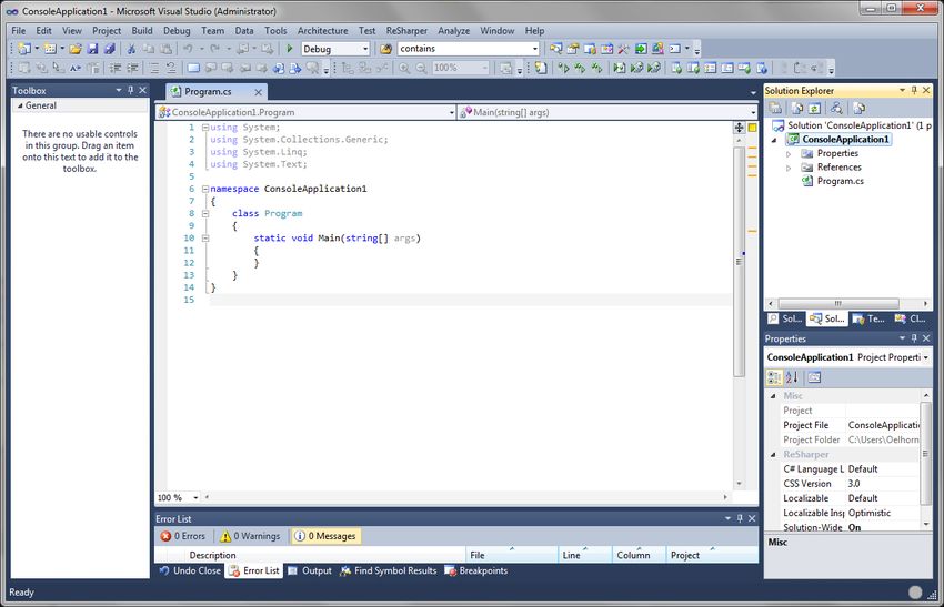
use the extension the user needs to open up their VS2010 and create a standard project, seen in Fig. 5-1.
11Fig. 5-1: Screenshot of a VS2010 project
From here the user has to ‘right click’ the project folder, choose Add -> New Item, pick an ASM file, name it
and ‘click’ Add. In this example the .asm file is named LightSwitch, shown in Fig. 5-2.
Fig. 5-2: Screenshot of a Add Item window
The newly added .asm file is now added to the project and opened up. Fig. 5-3 shows the opened .asm file.
To the right, is the toolbox containing the state- and transition tool. Here the user should fill in the name of
the ASM diagram, which is done in the properties window, in the lower right corner, that is displayed when
they ‘click’ on an empty space in the ASM diagram.
12Fig. 5-3: Screenshot of the opened .asm file
Now the user can add states to the diagram by ‘clicking’ on the state tool and dragging it into the diagram.
In this example two states have been added Off and On, shown in Fig. 5-4. The properties for the state are
shown in the properties window in the lower right corner, which is shown when the user ‘clicks’ on a state.
Here the kind of the state can be set. Off is set to Initial and On is set to Final.
Fig. 5-4: Screenshot of two added states
13Transitions between the states are added by ‘clicking’ on the transition tool, then ‘click’ on the state it
should go from, and then ‘click’ on the state it should go to. Fig. 5-5 shows the added transition between
the states. Its properties are also filled out in the lower right corner, when the user has selected the
transition. In the example the transition as the event/method call Switch, the condition counter >= 0 and
the action counter++.
Fig. 5-5: Screenshot of the added transition
To generate the C# skeleton code, the user ‘right clicks’ an empty space in the diagram and selects Validate
and Generate. The file can be found on the user’s desktop and can easily be shown in VS2010 by ‘double
clicking’ it. The generated code from the LightSwitch example can be seen in appendix B.
6 Code Contracts
Code Contracts is an extension to Visual Studio (VS) which brings the advantages of design-by-contract6
programming to all .NET languages. With Code Contracts it is possible to add preconditions, postconditions
and invariants to ones code. The contract is used to improve testing via runtime checking, enables static
contract verification, and documentation generation [7].
Using Code Contracts one restricts, in a good way, how the code can possibly behave. Other than helping
out the author of the code, the contract also helps other users of the code, whether they are working with
the actual code or working with a subclass of the code, since Code Contracts are inherited.
6
“An approach for designing software. It prescribes that software designers should define formal, precise and
verifiable interface specifications for software components, which extend the ordinary definition of abstract data types
with preconditions, postconditions and invariants.” Ref. Wikipedia
146.1 Precondition, Postcondition and Invariant
Code Contracts contains a lot of functionalities, so will only address some of the functionalities of
precondition, postcondition and invariant, which were part of the solution to the issue with not having the
possibility of using JML.
Preconditions, expressed by Contract.Require(…), for methods are conditions that have to be valid when
the method is invoked. All the variables used in the preconditions have to be of same accessibility as the
method itself or the condition cannot be satisfied by the method callers.
Postconditions, on the other hand, are conditions that have to be valid just before exiting the method, and
is expressed by Contract.Ensures(…). If a particular exception should be thrown in the postcondition, the
Contract.EnsuresOnThrow should be used. It is not recommended to use the type Exception for T, since
Exception is to “superficial”. The exception thrown will not address what the actual exception is, like stack
overflow or some other exception. T should be what a caller expects as part of the application
programming interface (API), e.g. FileNotFoundException. The last postcondition functionality that will be
addressed is OldValue. OldValue makes it possible to refer to the old value of an expression, expressed by
Contract.OldValue(e) where T is the type of e.
Invariants7 are also conditions. Invariants hold the terms for which an object of the class is in a “good”
state. So when an object of the class is visible to a client, these terms need to hold. Compared to the
conditions, the Invariants are declared in their own private void method. The method is identified with the
attribute [ContractInvariantMethod], and the individual invariants are specified with Contract.Invariant.
6.2 Issues with Code Contracts and Solutions
Comparing the generated JML specification from the paper [1] with the Code Contracts functionalities,
some issues occurred. The following example from the paper will be used to state the issues and solution.
(mode==LOCKED ==> \old(mode)==NORMAL || \old(mode)==LOCKED)
Firstly, code Contracts does not have a way of modeling constraints as JML does. The solution is to model
the JML constraints as Code Contracts invariants, since the constraint is an expression that returns true or
false, which is what invariant expressions also should do.
The next issue was to figure out how to get the previous value of the state. The postconditions in Code
Contracts have the OldValue method, but that is only available in postconditions. The states from the ASM
are modeled in the generated code by declaring an enumeration with the Enum keyword, as follows.
Enum State
{
State1,
State2,
…
};
7
Known as Object Invariants in Code Contracts, but will refer to them as Invariants in this paper
15Using an enumeration like this, it is possible to hardcode8 two fields that contain the value of the current
state and the previous state in the generated code, named _curState and _preState. These two fields are
used throughout the generated code to symbolize the state changes and to handle postconditions,
conditions in the methods and also the invariants/constraints. The _preState field solved the issue with not
having an OldValue method in the invariants.
The Enum State cannot be a value other than what is declared in the enumeration, which means that the
actual invariant in the paper [1], declared
mode==LOCKED || mode==CHALLENGED || mode==NORMAL
is not needed in the C# generated code. But since the current state and the previous state have to be one of
those three, what is the previous state of the initial state in the ASM? Hardcode an additional state, named
InvalidState, to the Enum State was the answer. So when an object of the class is created, the previous
state has the default value InvalidState. However, this means that one additional invariant needed to be
hardcoded, since the current state can possibly end up being InvalidState. Furthermore when the current
state is the initial state, the previous state can also be InvalidState or a valid state leading to the initial state.
The hardcoded invariants and the added InvalidState to initial state constraint are shown below.
Contract.Invariant(_curState != State.InvalidState);
Contract.Invariant(_curState == State.Normal ? (_preState == State.Challenged |
_preState == State.InvalidState) : true);9
The last issue was to model the “implies” notation ==>, since Code Contracts does not have that
functionality. Looking at the example at the beginning of this section, and using states instead of modes,
the constraint is “if the state is LOCKED, that implies that the old value of the state was NORMAL or
LOCKED”. The conditional operator “?:” in C#, also known as the ternary operator, is used to solve the
predicament. The ternary operator is expressed as condition ? expression_1 : expression_2 and returns one
of the two expressions depending on outcome of the Boolean condition. In other words, the condition
decides what expressions will be evaluated and the expressions determine the outcome of the entire
ternary expression, which is true or false. So the conditions can be used to check what the current state is,
the first part of the JML constraint example. If the second expression is set to default true, then the first
expression can be used to define what should be implied, the last part of the JML constraint example.
Leading to a ternary expression looking like this
_curState == State.Locked ? (_preState == State.Normal | _preState == State.Locked) : true
If current state is Locked, then the first expression will be evaluated, which states “Is the previous state
Normal or Locked?”. If the current state is not Locked then the second expression of the ternary will be
evaluated, which is true, hence the invariant will be not throw an error and move on to the next invariant in
the method.
8
Meaning that the specific code will always be in the generated code, no matter how the ASM is designed
9
This example code is from the generated code from the GSM authentication ASM
167 Building the DSL
When faced with a specific problem that occurs over and over e.g. designing an ASM, starting to code and
losing similarity between the code and the ASM. A way of solving the issue is to build a Domain Specific
Language (DSL) and add code generation to it.
The created extension contains two projects, Dsl and DslPackage. The Dsl contains the meta-model of the
extension, customized code by the use of the partial class mechanism and generated code. The DslPackage
contains; customized code, code that enables the DSL to be hosted and to interact with VS2010, where part
of the code is generated from the DslDefinition.dsl, which is the meta-model. Since there is a lot of
generated code, there will only be a walkthrough of the meta-model and a description of key points in the
customized code.
7.1 The Meta-model
The meta-model is shown in the DslDefinition.dsl in the Dsl project. The DslDefinition.dsl is in sense a “DSL
to create DSL’s”. There are two parts to it, shown in two “Swimlanes”, the meta-model10 in the left section
called “Classes and Relations”, and the graphical notation in the right section called “Diagram Elements”.
Fig. 7-1: Meta-model of the ASM extension
Fig. 7-1 shows the meta-model and graphical notation for the extension. The meta-model has two
concepts; StateMachine and State, and two domain relationships; StateMachineHasStates and Transition.
The link between the meta-model and the graphical notation is displayed by two connection lines from
State to StateShape and from Transition to TransitionConnector.
The StateMachine is the root concept, meaning that it is never really shown when the user designs an ASM,
since the root concept is the actual diagram. StateMachine has two domain properties, shown in Fig. 7-2.
Name for naming ones ASM which will be the name of the generated class, and Fields which are for adding
fields to the generated class.
10
Also referred to as Domain Model
17Fig. 7-2: The StateMachine element Fig. 7-3: The State element
The State is the only true concept the user really works with within the extension. State also has two
domain properties, shown in Fig. 7-3. Name for naming the states, and Kind to specify what kind of state it
is Normal, Initial or Final.
StateMachineHasStates, shown in Fig. 7-4, is an embedding relationship that links State to State, which are
the elements in StateMachine. An explanation to embedded relationships can be seen in section 7.1.1
below.
Fig. 7-4: The StateMachineHasStates relation
Fig. 7-5: The Transition relation
Transition is a reference relationship that links two State classes, shown in Fig. 7-5. The Transition
relationship has several domain properties, since it is from the transitions most of the generated code
comes from.
Label is the shown label on the transition which should be in the form Event(possible argument) [Condition]
/ Action. At the current time it is not a hard constraint but can be added in future version of the extension,
explained in 4.2. Event can be viewed as the method call which changes the current state from one state to
another state. Condition should contain the condition which needs to be met before moving from one state
to another state. Action is a possible action that can happen in the transition from one state to another,
e.g. exception thrown. Kind works the same way as for State, except there are only two kinds of transition
Normal- and Epsilon transition.
An important aspect of the properties of Transition is that the “Allow duplications” field is set to true, since
it should be possible to have more than one transition between two states.
7.1.1 Embedding and Reference Relations
In a meta-model every domain class, except the root, must be in relationship with at least one embedding
relationship. Without the embedding it will not be possible to see the model explorer, serialization would
not work and it would not be possible to create a tree of model elements. In other words, embeddings
18provide a path to navigate through the meta-model as a tree, where every element has exactly one parent
element.
With the embedding relationship some constraints follow. The multiplicity on the target role must be 1 or
0..1, because a model element can only be embedded once. Another constraint is, e.g. the root has several
embeddings to several targets, the targets have to have the multiplicity 0..1 because only one model
element can be embedded by one of those relationships at a time. Having one of the targets multiplicity as
1 would render all the other relationships impossible to instantiate. Furthermore the default deletion of a
parent of an embedding, deletes also the child of the embedding.
Reference relationships, on the other hand, represents any kind of relationship which is not embedded and
does not have constraints like embedded relationships. Generally a reference relationship can refer from
any model element to any other model element, and the multiplicity is often 0..* on the roles. It is even
possible to make a reference relation between two relationships, since links are themselves model
elements. By deletion of a parent of a reference relation, it is only the parent and the reference link that
gets deleted not the child of the relationship.
7.1.2 Allow Duplications
The transition allows duplications in the properties of Transition in the meta-model. Keeping this in mind,
one needs to be aware, when using the Successor and Predecessor methods for states. For example, having
two states with two transitions between them, shown in Fig. 7-6, gives the successor list from State 1
“State 2, State 2”, even though there is only State 2 as the successor.
Fig. 7-6: Two states with to transitions
If not aware of this, then the generated code will contain the double amount of constraints for the two
states in Fig. 2-1. When asking for the “link” between a state and a successor, another issue occurs. Below
is C# code for getting the “link” between each state in the ASM and each of their successors.
foreach (var state in sm.States)
{
foreach (var successor in state.Successor)
{
ReadOnlyCollection transitions = Transition.GetLinks(state, successor);
}
}
If using the example of the two states in Fig. 2-1, then you will get two transitions for each successor,
meaning you will get four transitions in total, since there are two State2 in the successor list. This means,
that there will be double as many methods, conditions and postconditions in the generated code. Hence
there will be N2 as many methods with conditions and postconditions in the generated code, where N is the
number of transitions. These issues have been take care of in the extension.
197.2 The Graphical Notation
The graphical notation of the ASM is designed after the principle of a control state ASM. States are squares
with round corners. The initial and final state is indicated with an icon, in the upper left corner of the state.
The initial icon is a fully black colored circle, and the final icon is a fully black colored circle with a ring
around it, equivalent to how an initial- and final state looks in a FA. Transition is an arrow from one state to
another. The epsilon transition is marked with an epsilon icon at the state, where the transition starts. The
notations can be seen in Fig. 7-7.
Fig. 7-7: Example of the ASM notation for the ASM extension
8 The Button
To activate the validation and code generation, a menu command has been added to the DSL. The menu
command is found in the context menu when the user right clicks on an empty space in their ASM diagram.
The menu command is named Validate and Generate.
The menu command can be defined so it is visible in the context menu in specific circumstances, or be
visible but grayed out. For example, the menu command can be visible but grayed out when they right click
an object in their ASM.
The reasoning for making the menu command only visible, when the user right clicks on an empty space in
the diagram, is that the validation and the generation should be done for the entire ASM not for selected
objects.
8.1 Declaring the Button and Functionality
The command is declared in the Commmand.vsct by adding a section/group in the menu and adding a
button to that section/group. To be sure that the command is only loaded in the DSL, a visibility constraint
is added. The GUIDs and IDs for the group and the button are defined in the Symbol section at the end of
the Command.vsct file. Several sections/groups and buttons can have the same GUID, but must have
different IDs. For a more detailed view of the code, look in appendix C.
The DSL already has some commands in the generated partial class CommandSet.cs, so to add the behavior
of the command a new partial class11 was added. The added partial class contains two methods to handle
the visibility of the command and the functionality.
The OnMenuMyContextMenuCommand method handles the functionality of the command button. It builds
the needed sets for the validation and code generation, explained in section 2.3. Furthermore the method
creates an object of the validation- and the code generator class, and calls the methods that validate the
ASM and generate the code. For a more detailed view of the code, look in appendix D.
11
Can be found in DslPackage\CustomCode
20A set of final states and a set of input symbols have been created, based on the definition of an FA, but
these sets are not used in the validation or the generation, since the transitions functions set holds the
same information. These are still kept in the code for the possibility of future work on the extension.
9 Validation
To generate the skeleton C# code, some validation rules have to be created to make it possible to generate
valid code. These rules are chosen by the author of the VS 2010 extension, because the Abstract State
Machine has to be more concrete to generate code from. Even though a state machine with one state is in
theory a valid state machine, it does not generate more code than a class with two fields and an
enumerator.
9.1 Chosen Rules
The validation rules are as follows;
1. The state machine has to have states
2. There has to be one initial state, and only one
3. States have to have a name
4. States cannot have the same name
5. Every state, except initial state, has to have a predecessor
6. Every state, except final state, has to have a successor
7. Every transition, except epsilon transition, has to have a label
8. Transitions with the kind Normal cannot have the exact same event, condition and action
The rules have been created on the assumptions that the user actually wants to generate code, 1st rule.
There has to be an initial state, and only one, in state machines, 2nd rule. Without a name on states and
filled in properties on a normal transitions it is not possible to generate methods or the Code Contracts, 3rd
and 7th rule. States could have the same name, but to keep the user from making the ASM to confusing
with too many states with the same name the 4th rule was created. The 8th rule is in essence the definition
of a deterministic state machine, which is described in section 2.3.
The 5th and 6th rule makes sure that all the states in the ASM are connected, so it is not possible for the user
to create two ASMs in the same diagram. Furthermore the rules also say, together with 1st and 2nd rule, that
there has to be an initial state and a transition to one other state, shown in Fig. 9-1, which means that the
user has to create this as a minimum if they want to generate code.
Fig. 9-1: ASM diagram containing the minimum about of states and transitions
Also if the ASM’s last state is not a final state, there have to be a transition leading to itself, else it breaks
the 6th rule and an exception is thrown, example shown in Fig. 9-2.
21Fig. 9-2: ASM diagram with accepted last state, not marked as final
9.2 Considered Rules
In the process of choosing the right rules for the ASM other rules have come up in discussions. Rules such
as;
Must the ASM contain one final state?
Should the ASM only have one final state?
Should infinite loops be allowed in the ASM?
When designing state machines it is good practice to have an initial state and a final state, but sometimes it
is needed to design a system which should not stop running at any point, e.g. the state machine in the
Hubbers and Martijn paper [1], where the state Locked is the “final state” but it doesn’t shut down the
system. Therefore it should not be mandatory to have a final state.
With regards to having more than one final state, it is a matter of design and overview of the system. One
could argue that several final states would make the ASM look cluttered, but having transitions running
from several states to the final state through all the other transitions would cause the same issue. So, it is
possible to have more than one final state.
Most often infinite loops in systems, algorithms etc. are considered a bug. But there are situations where
users want to model a system, where there should be an infinite loop, such as reactive systems like
websites. So having the possibility of modelling an infinite loop in the ASM extension seems reasonable, but
there should be a prompt about an existing infinite loop. This feature can be implemented in future
versions of the extension, also written in section 4.2.
9.3 The Code
For validating the ASM the class Validation12 has been created, which takes three arguments; states,
inputSymbols and startState. They are all of type HashSet, since the same arguments are used in the code
generator. The code generating class takes arguments sets because of the DFA and NFA definition,
described in section 2.3.
One could argue against having the startState of type HashSet since there is only supposed to be one initial
state, but keeping all the validation together in one file, rather than several places trough out the DSL, was
the only reason for it.
Since the validation is based on the rules written in section 9.1, the solution for the validation are if-
statements where an exception is thrown, when the ASM does not adhere to the rules.
For a more in depth view of the code, see appendix E.
12
Can be found in DslPackage\CustomCode
2210 Generating C# Code
The C# code is generated in the CodeGenerator.cs13 class. The class uses the argument sets containing the
ASM states, the ASM name, the ASM fields, the transition function from the ASM and the initial state.
The process of generating the code is sequential where each bit of code is created in a “builder” method,
added to a StringBuilder and gets written to the .cs file with the name of the ASM. The sequence of how the
code is built and written to the file can be seen in Fig. 10-1. The sequence does not show the formatting
methods for the generated code.
DirectiveBuilder NameSpaceBuilder ClassBuilder FieldBuilder
MethodBuilder EnumBuilder ConstructorBuilder
Postcondition-
Builder
ChangeState-
ConstraintBuilder ClosingBrackets
MethodBuilder
ConditionBuilder
ActionBuilder
Fig. 10-1: The sequential flow of code generation
In Fig. 10-1 the black arrows symbolizes what is written to the file. The PostconditionBuilder, Condition-
Builder and ActionBuilder are not written directly to the file, but are part of what the MethodBuilder
creates, shown with light blue- and red arrows.
The idea of only using one String as the container for the created code was thought of, but since there is no
limitation to the size of the ASM, it could be possible to go over the maximum amount of bits a String has.
As a precaution a StringBuilder was chosen as a container instead, where at the beginning of each “build
method” the StringBuilder is cleared, since the code from the previous “build method” have already been
written to the .cs file.
While the code is being generated, formatting is added to it, so the code looks like standard C# code. To do
this some formatting methods were created, named Tab, StartBracket and EndBracket. These three
methods work together with the bracketCounter to keep track of how many tabs are in front of each line of
code. This is done by incrementing the bracketCounter each time a start bracket ‘{‘ is added to the code,
and decrementing the bracketCounter when an end bracket ‘}’ is added. Since the generated code is
13
Can be found in DslPackage\CustomCode
23written to the file as it gets build, there are a lack of end brackets at the end of the file. The ClosingBracket
method takes care of this together with the formatting methods and the bracketCounter.
The source code for CodeGenerator.cs can be seen in appendix F.
10.1 The Generated Code
An equivalent ASM to the GSM authentication state diagram, have been created to show what the
CodeGenerator class generates. The GSM authentication state diagram can be seen in section 3, where as
the equivalent ASM using the ASM extension, is shown in Fig. 10-2.
Fig. 10-2: GSM authentication ASM
The generated code from the ASM can be seen in appendix G.
In the generated code, one can see that transition Event is equivalent to a method call with the same name.
The transition Condition is an if-statement containing what the current state should be and what conditions
needs be met for the state change. The transition Action is what happens in the if-statement if it is true,
hence the conditions are met.
The accessibility of the class and the different methods are not written, which means that they are Private
by default in C#. It is up to the user of the code to add the appropriate accessibility.
11 Test
The test will be divided up into two, one that covers validation and one that covers code generation. The
validation test will be done with test cases, whereas test of the code generation will be done by creating an
ASM that has 100% code generation coverage.
11.1 Validation test
To test the validation code, test cases have been created to trigger the exception handlers. The test cases
are black box testing, so they are bases on the validation rules, described in the validation paragraph, and
not derived from the code.
24Preconditions for the test cases are; operation system is Windows, using VS 2010 Ultimate and ASM
extension installed.
Postcondition for the test cases is; an exception is thrown.
Test Case Input Output
Exception thrown:
1 (Empty ASM)
“The ASM has to have states”
Exception thrown:
“There have to be one initial
2
state, and only one”
Exception thrown:
“States have to have a name”
3
Exception thrown:
“States can’t have the same
4
name”
Exception thrown:
“Every state, except initial state,
has to have a predecessor”
5
Exception thrown:
“Every state, except final state,
6
has to have a successor”
Exception thrown:
“Every transition, except epsilon
7
transition, has to have a label”
Exception thrown:
“Transitions cannot have same
8
event and condition and action”
11.2 Generation test
Test of the generation code is done with an ASM which will give 100% code coverage. To display the 100%
code coverage a Boolean array, with the length of the number of methods in the generation code, has been
created. A method called CheckMark have been created which changes the Boolean value in the array, at a
specific index, from 0 to 1 if it is not 1 already.
25Each index in the array is equivalent to a method in the generation code, so when the method is called, the
CheckMark method is called. The CheckMark method takes the method number as an argument and
changes the value at the index number in the array.
The used ASM for the test is the ASM shown in Fig. 10-2, above.
Below is the result of the test coverage.
Test Coverage Results:
True True True True True True True True True True True True True True True True True True True
True True
12 Conclusion
The outcome of this thesis is a VS2010 extension, where users have the possibility to create an ASM and
generate contracted C# skeleton code from it. The generated code uses Code Contracts to keep the
constraints of the ASM diagram.
ASMs are used to describe hardware and software systems. They help contractors and developers to create
a common view of how the system should be put together and what it should contain. The ground model of
the ASM can be split up into stepwise refining ASMs, which describes more in-depth how a state in the
ground model should work.
Programming the stepwise refining ASM is a time consuming process for programmers and they can easily
lose the equality between the ASM and the code they have created. The created extension would solve this
problem.
Using Code Contracts did raise some issues since it does not have the same features as JML specifications.
The issue with “implies” from the JML specifications was solved with the ternary operator. Constraints are
modeled as invariants with the ternary operator. The OldValue functionality cannot be used in other places
than postconditions, so hardcoding a previous state field in the code was necessary.
Future versions of the extension could hold features such as hard constraints to the transition properties, a
feature where the user gets prompted about an infinite loop in the created ASM, the possibility of
generating an ASM diagram from C# code, and the feature to generate XML code for third party software
like UPPAAL.
2613 Literature List
[1] Engelbert Hubbers, Martijn Oostdijk. Generating JML Specification from UML State Diagrams.
http://citeseerx.ist.psu.edu/viewdoc/download?doi=10.1.1.183.4351&rep=rep1&type=pdf
[2] Egon Börger, Robert Stärk. Abstract State Machines: A Method for High-Level System Design and
Analysis. ISBN 3-540-00702-4
[3] John E. Hobcroft, Rajeev Motwani, Jeffrey D. Ullman. Introduction to Automata Theory, Languages,
and Computation. Second Edition. ISBN 0-201-44124-1
[4] Steve Cook, Gareth Jones, Stuart Kent, Alan Cameron Wills. Domain-Specific Development with Visual
Studio DSL Tools. ISBN-13: 978-0-321-39820-8
[5] Microsoft Corporation. Code Contracts User Manual. January 8, 2012
[6] Egon Börger. The Abstract State Machine Method for High-Level System Design and Analysis.
http://www.di.unipi.it/~boerger/Papers/Methodology/BcsFacs07.pdf
[7] Microsoft Research/Microsoft Corporation. Code Contracts.
http://research.microsoft.com/en-us/projects/contracts/
[8] R. N. Taylor, N. Medvidovic, E. M. Dashofy. Software Architecture: Foundations, Theory, and Practice.
ISBN-10: 0470167742
[9] Martin Fowler. UML Distilled: A Brief Guide to the Standard Object Modeling Language. Third Edition.
ISBN 0-321-19368-7
2714 Software
Product name: Microsoft Visual Studio 2010 Ultimate. Version: 10.0.30319.1 RTMRel.
Product name: Microsoft Code Contracts (academic) 1.4.40602.0 for .NET. Filename: Contracts.msr9.msi.
Authors: Microsoft Corporation. Revision number: {22366D81-6B52-4B5C-AD79-153DEFD6641D}
Product name: Visualization and Modeling SDK. Filename: vs_vmsdk.exe. Authors: Microsoft Corporation.
File version: 10.0.30319.2.
Product name: Visual Studio SDK. Filename: VsSDK_sfx.exe. Authors: Microsoft Corporation. File version:
10.0.30319.1.
28Appendix A
XML code for the GSM authentication ASM
29Appendix B
Generated C# Code from Light Switch ASM
using System;
using System.Collections.Generic;
using System.Linq;
using System.Text;
using System.Diagnostics.Contracts;
namespace LightSwitch
{
class LightSwitch
{
State _curState;
State _preState;
int counter = 0;
LightSwitch()
{
_curState = State.Off;
_preState = State.InvalidState;
}
enum State
{
InvalidState, // Do NOT remove this state, used in Code Contracts
Off,
On
}
void Switch()
{
Contract.Ensures((_preState == State.Off & counter >= 0) ? _curState == State.On : true);
if (_curState == State.Off & counter >= 0)
{
StateChange(State.On);
counter++;
}
}
private void StateChange(State name)
{
_preState = _curState;
_curState = name;
}
[ContractInvariantMethod]
private void ObjectInvariantsAndConstraints()
{
Contract.Invariant(_curState != State.InvalidState);
Contract.Invariant(_curState == State.Off ? _preState == State.InvalidState : true);
Contract.Invariant(_curState == State.On ? _preState == State.Off : true);
Contract.Invariant(_preState == State.Off ? _curState == State.On : true);
}
}
}
30You can also read