PULSAR 7 Radiotracer System Description and Specification - Technical Publication
←
→
Page content transcription
If your browser does not render page correctly, please read the page content below
Technical Publication
PULSAR® 7 Radiotracer System
Description and Specification
Revision G
Copyright 2004, AccSys Technology, Inc.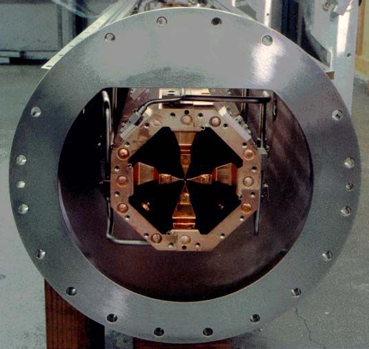
Rev. G—6/30/04                                                                                PULSAR® 7 Description and Specification

Contents
1.     GENERAL COMMENTS .......................................................................................... 4

2.     PHYSICAL FEATURES ........................................................................................... 4
2.1          MODEL PL-7 RF LINEAR ACCELERATOR ..............................................................................4
     2.1.1         Ion Injectors ............................................................................................................................ 5
     2.1.2         Radio Frequency Quadrupole (RFQ) ...................................................................................... 6
     2.1.3         Drift Tube Linac (DTL) Tanks................................................................................................ 7
     2.1.4         Vacuum and Cooling Systems ................................................................................................ 9
     2.1.5         Radio Frequency (RF) Power Systems ................................................................................... 9
     2.1.6         Control System...................................................................................................................... 11
2.2          RADIOISOTOPE PRODUCTION TARGETS ...............................................................................11
     2.2.1         Fluorine-18............................................................................................................................ 11
     2.2.2         Carbon-11.............................................................................................................................. 12
     2.2.3         Oxygen-15............................................................................................................................. 12
     2.2.4         Nitrogen-13 ........................................................................................................................... 12
     2.2.5         Target Mounting and Target Support.................................................................................... 12
2.3          TARGET SHIELDING UNIT ...................................................................................................13
2.4          RADIOTRACER PROCESSING MODULES ...............................................................................13
     2.4.1         Simple Radiotracers, Radiotracer Precursors & Intermediates ............................................. 13
     2.4.2         Radiotracer Synthesis Units .................................................................................................. 13
3.     FACILITY GUIDELINES......................................................................................... 15
3.1          GENERAL REQUIREMENTS ..................................................................................................15
3.2          OTHER CONSIDERATIONS....................................................................................................16
3.3          SUGGESTED SURFACE FINISHES. .........................................................................................17
4.     Example layouts..................................................................................................... 18

Mkt01—\\Hera\marketng\Specifications\PULSAR(tm) Tech Description Rev G.doc                                                                                        2
Rev. G—6/30/04 PULSAR® 7 Description and Specification Revision History Rev Date Reason for Change A 20 Nov. 1995 First edition B 20 Feb. 1996 Update Section 3.2.2 C 20 Oct. 1998 Final Copy D 22 Feb. 1999 Updated figures E 08 May 2001 Update target information F 02 Dec 2002 Update linac & shield information G 30 June 2004 Update figures Mkt01—\\Hera\marketng\Specifications\PULSAR(tm) Tech Description Rev G.doc 3
Rev. G—6/30/04                                                         PULSAR® 7 Description and Specification

1. GENERAL COMMENTS
A PULSAR® 7 system consists of a PL-7 rf proton linear accelerator (linac) for acceleration of
H+ ions to 7.0 MeV energy integrated with up to three targets for production of the four common
positron emitting radioisotopes, fluorine-18, carbon-11, nitrogen-13 and oxygen-15. The
standard PULSAR® 7 configuration is illustrated in figure 1. This totally integrated system uses
a PC-based control system, including commercial control modules and a PC operator interface
based on LabView©. The standard PULSAR® 7 system usually includes an integrated neutron
and gamma shield surrounding the target module only, as shielding is not required around the
linac. Commercially available radiotracer processing modules for the automated production of
labeled precursors and intermediates as well as finished radiotracers can be provided.

         Figure 1. PULSAR® 7 system including Model PL-7 rf linac, target module & shield.

2. PHYSICAL FEATURES
A standard PULSAR® 7 system consists of three major subsystems:
    •    The Model PL-7 proton linac, which produces an output beam at 7.0 MeV.
    •     The radioisotope target module, including the high energy beam transport (HEBT), the
         beam switching or target changer, the targets and target support systems and the target
         shielding.
    •    The radiotracer processing modules, which convert the radioisotopes into labeled
         intermediates and precursors for use directly or for synthesis into complex radiotracers.

2.1 Model PL-7 RF Linear Accelerator
The Model PL-7 linac in the PULSAR® 7 consists of the following subsystems:

Mkt01—\\Hera\marketng\Specifications\PULSAR(tm) Tech Description Rev G.doc                                       4
Rev. G—6/30/04 PULSAR® 7 Description and Specification
• The ion injector creates a pulsed 30 keV ion beam using a duoplasmatron ion source
(H+). An electrostatic lens is then used to match the beam from the ion source to the
RFQ.
• The Radio Frequency Quadrupole (RFQ) simultaneously focuses, efficiently bunches and
accelerates the beam to 3.5 MeV before it enters the DTL tank.
• The Drift Tube Linac (DTL) accelerates the proton beam from the RFQ to 7.0 MeV.
• Modular rf power systems provide radiofrequency power for the RFQ and DTL sections.
• A PC-based control system, using commercially available hardware modules and
LabView© software.
• Vacuum and cooling systems.
This compact linear accelerator has the operating specifications listed below in Table 2.1.
Table 2.1. Model PL-7 RF Linac Specifications
Particle H+
Energy 7.0 MeV
Current > 100 µA
Size (L x W x H) 18.3 ft x 2.5 ft x 5.5 ft
Weight 3 tons
Input AC Power 25 kW
Cooling Water 20 gpm
2.1.1 Ion Injector
The ion injector produces a 15 to 20 mA beam of H+ ions for injection into the RFQ. The
injectors operate at 30 keV, with all high voltage components isolated inside grounded
enclosures. The H+ ion source is the duoplasmatron that has been used in most high energy
accelerators for many years.
The duoplasmatron uses an oxide-coated nickel gauze cathode that normally requires 100 W of
input power to generate the hydrogen plasma. A self biased boron nitride plasma expansion cup
is used to improve the atomic ion fraction of the hydrogen beam extracted from the source. The
source's focusing electrode compensates for the non-uniformity of the plasma extraction surface.
The source is operated at 30 kV and the ion beam is extracted across a single gap with an
extractor electrode at ground potential. Small permanent magnets are used to suppress electrons
from backstreaming into the extraction gap. Typical operating parameters for this ion source are
listed in table 2.1.1.
Mkt01—\\Hera\marketng\Specifications\PULSAR(tm) Tech Description Rev G.doc 5Rev. G—6/30/04 PULSAR® 7 Description and Specification
Table 2.1.1. H+ Injector Operating Parameters
Extracted beam Current 20-25 mA
Hydrogen Gas Consumption ≅ 1.0 atm-cc/min
Output Beam emittance 0.05 πcm-mrad
Extraction Voltage 30 kV
Plasma Aperture Diameter 0.025 inches
H+ Component of Beam ≅ 90%
Maximum Filament Power 150 W
Nominal Arc Current (Pulsed) 20-25 A
Input Power (220 V) 1 kW
All ion source power supplies are isolated at 30 kV in a small grounded electronics rack located
beneath the accelerator and power is fed to the ion source through a short shielded umbilical.
This injector electronics rack contains the 30 kV power supplies for the ion source and einzel
lens, the master pulsing and timing controls and the vacuum control and monitoring units.
Low Energy Beam Transport (LEBT). The LEBT links the ion injector with the RFQ
accelerator section. An Einzel lens (a cylindrically symmetric, dual gap electrostatic lens) is used
to focus the beam from the ion source into the RFQ. This compact focusing lens is mounted on
the input of the RFQ and it only requires one high voltage power supply to operate it.
2.1.2 Radio Frequency Quadrupole (RFQ)
The RFQ is an accelerating structure that simultaneously accelerates, focuses and bunches a high
current, low energy ion beam. The electric fields that focus, bunch and accelerate the ions are
produced by a high frequency alternating current applied to four narrow metal vanes with
precisely-machined rippled edges. The ion beam passes through the open center of this structure.
The fields generated between opposing vanes focus the beam and confine it to a narrow region
along the axis of the RFQ. The ripples on the vane tips produce a field along the axis that first
gently bunches the ion beam, and then accelerates it to the final energy.
As illustrated in figure 2.1.2., the RFQ incorporates a unique geometry for the vanes and
resonator in which the RFQ consists of four identical vane sections machined from custom
aluminum extrusions. The extrusion provides a continuous water cooling passage along the vane
very near the vane tip. These cooling channels are used to regulate the structure's temperature to
stabilize the resonant frequency. The four segment geometry produces uniform thermal control
for the vanes and the resonator walls because it eliminates thermal isolation of the parts of the
structure. Several small tuners are placed in openings along each quadrant: these are used at the
factory to fine tune the field components, and require no further adjustments during normal
operation of the system.
Mkt01—\\Hera\marketng\Specifications\PULSAR(tm) Tech Description Rev G.doc 6Rev. G—6/30/04 PULSAR® 7 Description and Specification
Figure 2.1.2. RFQ UniVane1 design.
The RFQ resonator cavity does not serve as a vacuum chamber. Instead the entire RFQ is placed
in a simple cylindrical vacuum chamber with vacuum feedthroughs for the rf drive loop, the
water cooling, and rf pick-up loops. This decouples the rf and vacuum seals, while allowing a
rigid vacuum system with internal alignment of the RFQ. A single 3-1/8" coaxial drive loop
couples the rf power into the RFQ at the nominal operating frequency of 425 MHz. The RFQ is
powered by an AccSys Model 12TW350 rf power system.
Table 2.1.2. Model PL-3.5 RFQ Accelerator Parameters.
Nominal Operating Frequency 425 MHz
Accelerated Ions H+ or H−
Injection Energy 0.030 MeV
Final Ion Energy 3.50 MeV
Design Input Current 18 mA
Current Limit 30 mA
Beam Transmission > 80 %
Total Length 2.5 m
Total RF Power (Theoretical x 1.4) 220 kW
2.1.3 Drift Tube Linac (DTL) Tanks
Attached to the high energy end of the RFQ is a short drift tube linac (DTL). It consists of a
large diameter metal tank with a series of “drift tubes” along the axis, as seen in figure 2.1.3. The
1
US Patent Number 5,315,120
Mkt01—\\Hera\marketng\Specifications\PULSAR(tm) Tech Description Rev G.doc 7Rev. G—6/30/04 PULSAR® 7 Description and Specification
radio-frequency energy coupled into the tank creates an alternating axial electric field along the
centerline of the chamber. The injection timing of the ion bunches from the RFQ and the
dimensions of the drift tubes and the spacing between them is such that the ions are accelerated
from 3.5 MeV to 7.0 MeV in the DTL section. This type of ion accelerator is more efficient than
the RFQ, but requires an input energy in excess of 2 MeV. Closely coupling this DTL to the
RFQ eliminates the need for a complex beam matching section between the two.
Figure 2.1.3. AccSys Drift Tube Linac2 Tank Section
The DTL consists of the following main components:
• RF/Vacuum Vessel
• Drift-Tubes
• Post-Stabilizer Assemblies
RF/Vacuum Vessel. The DTL tank is made of steel and is copper plated. Each section consists
of two rails, an upper and a lower, joined together by welding two circular wall sections between
them. The upper rail supports the drift-tubes as well as two tuning bars used for coarse frequency
adjustments. The bottom rail increases structural stability while providing mounting surface for
additional tuning bars and vacuum pumps. The post-stabilizer mounts, the slug tuner ports, and
other vacuum penetrations are welded directly to the tank's walls.
Drift-Tubes. The drift-tube stems are made of copper plated stainless steel. They are copper
plated and brazed into the solid copper drift-tube bodies. The drift-tube bodies have internal
cooling channels that are fed through the stem. Compact permanent magnet quadrupoles are used
in the drift-tubes to maintain transverse beam focusing. Each drift tube is sealed to make a
2
US Patent Number 5,179,350
Mkt01—\\Hera\marketng\Specifications\PULSAR(tm) Tech Description Rev G.doc 8Rev. G—6/30/04 PULSAR® 7 Description and Specification vacuum tight enclosure for the permanent magnet quadrupoles mounted inside. The cooling channels are also sealed separately within the drift tubes. The drift-tube rf surfaces are made from copper shells that fit closely over the drift-tube body and are joined to a copper ring using electron-beam welding. These surfaces are cooled by the water channels in the drift-tube body near the welded joints. In the DTL tanks, the drift-tubes are mounted to adjustable sockets on the upper rail so that they can be rigidly aligned with little residual stress. Accurate positioning of the drift-tubes is accomplished using shims for precise incremental adjustment with long-term stability. Drift-tube assemblies can be removed and re-installed to less than ±0.0005 inches of the initial position. Post-Stabilizer Assemblies. The DTL uses resonant post-stabilizers to stabilize and fine tune the on-axis electric field distribution. They are adjusted using the tilt-sensitivity method. The post-stabilizers are mounted in an adjustable mount that allows precision movement of the posts during tuning. The post-stabilizer adjustments are independent of the rf and vacuum seals. 2.1.4 Vacuum and Cooling Systems Vacuum System. The ion injector provides the main gas load into the system. The H+ ion source uses an 8" cryopump to pump the hydrogen gas load in the injector from the ion source, while maintaining a vacuum sufficient to prevent any sparking in the extraction gap. The higher gas load from the H− ion source requires a 10" cryopump. The pressure in the injector vacuum chamber is typically 2-3 x 10⁻⁶ torr during operation. Differential pumping of the RFQ vacuum chamber is provided by the restricted openings of the ground electrode and Einzel lens. A second cryopump removes any hydrogen gas leaking from the injector into the RFQ's vacuum chamber. The DTL is kept under high vacuum by a third cryopump connected to a port at the bottom of it. A vacuum gauge unit which uses two ion gauges and two thermocouple gauges monitors the pressure in the ion injector, in the accelerator, and in the roughing lines. This unit provides local indication of pressure readings on its from panel and sends this information to the control system. A vacuum control system is provided to open and close valves, turn vacuum pumps on and off in appropriate sequence, and provide the system interlocks. The vacuum system can also be operated locally, typically at the ion injector electronics cabinet. Cooling System. The rf amplifiers and the ion injector require de-ionized cooling water, provided by a commercial closed-circuit system, for proper operation. Another closed-circuit cooling system maintains the operating temperature of the RFQ and DTL. The temperature of the structure is stabilized by providing temperature-controlled water through channels in the RFQ vanes and on the outside of the DTL tank walls as well as through the drift-tube assemblies and post-stabilizers. 2.1.5 Radio Frequency (RF) Power Systems The RFQ and DTL sections use pulsed rf power systems operating at 425 MHz to provide the power to generate the accelerating fields in the accelerator cavity and the power transferred to the ion beam. These modular rf power systems were designed for rf linacs and other applications requiring wide bandwidth amplitude and phase control. They use 12 commercially available Mkt01—\\Hera\marketng\Specifications\PULSAR(tm) Tech Description Rev G.doc 9
Rev. G—6/30/04                                                         PULSAR® 7 Description and Specification

planar triode tubes in a parallel self-branching array as the final power stage. Special circuits
ensure equal power contribution from each tube. The planar triodes have large-area oxide-coated
cathodes. The peak power output is more that 1 kW per Watt of heater power. Figure 2.1.5. is a
block diagram of the rf power amplifier system including phase, amplitude and frequency
control. Nominal peak output power is 350 kW. The rf power systems include load fault
protection, and dynamic amplitude and phase control to within ±1/2% and ±2° respectively, with
less than 3.0 µsec response time.

                                Figure 2.1.5. 350 kW RF Amplifier Schematic.

The amplitude of the rf power amplifier system is adjusted through a feedback system until the
detected linac cavity field is equal to the amplitude reference voltage. Frequency control is
obtained by phase locking the linac resonant frequency to the rf system master oscillator. The
intermediate power amplifier stage of these units is a tuned line amplifier. The second stage has
two planar triodes in parallel to provide 25 kW output. The first stage uses a single tube to
provide 2.5 kW drive to the second stage. The driver amplifier is a solid state unit capable of
supplying 150W at up to 100% duty factor with 150 mW of drive. The systems require 100 mW
CW drive power.

The amplifier stages are operated class C for stability at high gain with pulsed rf drive. The tubes
are protected by electronic crowbar circuits that limit fault energy dissipated in a tube to a safe
value. The systems are designed for operation with a high Q resonant cavity load, with the
amplifier, transmission line and resonant cavity loads tuned together. The tuned output circuit
handles the high turn-on and turn-off VSWR without rf power isolators.

The built-in control loops for amplitude, phase and frequency respond rapidly to changes in load
cavity fields. The amplitude control loop uses high level cathode modulation of the power
amplifier stage. The rf systems have a built-in control and monitor chassis which interfaces to

Mkt01—\\Hera\marketng\Specifications\PULSAR(tm) Tech Description Rev G.doc                                       10
Rev. G—6/30/04 PULSAR® 7 Description and Specification
the control computer through the data bus. The units are fully interlocked and all units are
supplied in EMI shielded cabinets.
2.1.6 Control System
The PL-7 rf linac has a fully integrated PC-based control system that provides real-time control
and monitoring of the entire system, including the FDG chemistry module. This system uses data
acquisition and control components commercially available from Group III that are interfaced to
a personal computer. The software is built on LabView©, a widely used software package
designed for control and data acquisition. All interlocks and primary feedback circuits are
implemented in hardware, with no software dependence.
The control system is menu-driven−operators use menus to select the area of the system they
need to control or monitor. All menus and screens are intuitive and easy to learn. Comprehensive
on-line help information is readily accessible at all times. The control system includes complete
data logging and save and restore capability. A large complement of automated procedures in
included with the control system software.
2.2 Radioisotope Production Targets
PULSAR® targets for the production of fluorine-18, carbon-11 and oxygen-15 were developed
by modifying cyclotron targets used for producing these radioisotopes. An innovative design for
the target window has overcome the two challenges of the PULSAR® 7, which were the 7.0
MeV proton beam energy and the 100 Hz pulsed beam with a 1.3% duty factor. The targets
designed for the PULSAR® system function as an integral part of it.
2.2.1 Fluorine-18
The nuclear reaction of choice is the widely used 18O(p,n)18F, which produces 18F in the form of
fluoride ion. A compact, high performance water target3 for use with the PULSAR® systems has
been developed in collaboration with Brookhaven National Laboratory. The target is of the
classical water target design, with a silver target body and running in the sealed mode. A water
cavity of 25 mm diameter with a depth of 0.3 mm is used. The front foil is 0.001 inch thick
titanium supported by a 75% transparent support grid. The beam energy through the titanium foil
is 6.5 MeV and exits the water cavity at 3.0 MeV. The target is run in the closed mode at a
pressure of 300 psig during bombardment. Total target volume is 340 µl, with 165 µl in the beam
strike area and 175 µl target dead volume.
The target is remotely loaded and unloaded through small diameter PEEK tubing (0.25 mm ID).
PEEK tubing (0.25 mm ID) serves as a target vent line as well. For loading, the vent line is
opened and a syringe pump forces 18O-water through the load line to fill the target from the
bottom. The load line is closed, and 300 psig of argon pressure is applied through the vent line at
3
US Patent Number 5,915,874
the top of the target. The vent line is closed, leaving the target under 300 psig of argon pressure.
At EOB, the load/unload line is opened and the argon pressure forces the 18F-fluoride solution
from the target into the FDG synthesis unit or a suitable transfer vessel.
Mkt01—\\Hera\marketng\Specifications\PULSAR(tm) Tech Description Rev G.doc 11Rev. G—6/30/04 PULSAR® 7 Description and Specification The syringe pump, vent valve and delivery valve are PC controlled, and their status along with the system pressure can be shown on the PULSAR® operator's display. The target is loaded in less than 2 minutes. After EOB, solution from the target is delivered to a site of use up to 50 ft away within 1 minute. Yield for 60 µA of beam on target for 60 minutes is about 1,000 mCi. 2.2.2 Carbon-11 The nuclear reaction of choice is 14N(p,α)11C, which is commonly used for positron isotope production. The water cooled target is machined from aluminum. It is conical in shape, expanding in diameter from 2 cm in front to 4 cm at the back, with a length of 10 cm. Similar to the fluorine-18 target, the front foil is 0.001" thick Havar supported by a 70% transparent support grid. The beam energy exiting the Havar foil is 6.5 MeV. The target is filled through PEEK tubing (0.25 mm ID) with 14N-nitrogen gas to 100 psi with beam off. The system is run in static mode. Yield for 40 µA of beam on target for 40 minutes is 600 mCi of 11C-carbon dioxide (CO2). 2.2.3 Oxygen-15 The nuclear reaction is 15N(p,n)15O; and the target is identical in all respects to the 11C production target. The only difference for production of 15O is that the target is filled with 15N- N2. The system is run in static mode only. Yield for a 40 µA beam on target for 10 minutes is 600 mCi of 15O-molecular oxygen. 2.2.4 Nitrogen-13 The nuclear reaction of choice is 13C(p,n)13N. The detailed design remains to be determined. The use of a solid 13C-matrix, either microparticles in a liquid or gas suspension or a thin film or thick surface, for direct or indirect production of 13N-ammonia is one category of approaches. Use of an innovative proprietary solid ionic 13C-matrix target material is also under evaluation. In this case, heating of the target in a hydrogen atmosphere after irradiation releases 13N in the form of ammonia. A method which produces 13N-ammonia directly is preferred to one which requires post irradiation processing (e.g., reduction of 13N-NOx by DeVarda’s alloy). Yield after 40 µA on target for 20 minutes is 30 mCi of 13N-ammonia. 2.2.5 Target Mounting and Target Support All PULSAR® 7 targets are mounted behind a vacuum isolation valve on a compact, three target changing module. Beam switching (H+ or H−) or beam sharing (H− only) can be used to deliver the beam to the targets simultaneously only in the unshielded version. All targets use the same quick connect mounting mechanism. The target support and changing module includes the physical mount for the targets as well as for the cooling water, compressed gases, filling and emptying lines, and electrical and electronic wiring and connections. PULSAR® systems do not require direct foil cooling by blowing a stream of cold He across the target foil face, as there is only a single window. Thus, there is no recirculating He system. A standard arrangement of support ports for fluids and contacts for electrical and electronic connections is common on all target assemblies. Quick connect couplings are used to attach targets to the target module, and also to make the fluid and electrical connections. Mkt01—\\Hera\marketng\Specifications\PULSAR(tm) Tech Description Rev G.doc 12
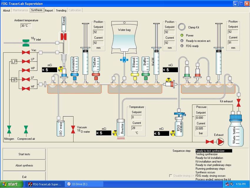
Rev. G—6/30/04                                                         PULSAR® 7 Description and Specification

2.3 Target Shielding Unit
Design of the target shielding unit for the PULSAR® 7 used the latest empirical data, theoretical
modeling methods, and unique material and fabrication techniques to assure ease of installation
and outstanding performance. The target shield unit is mounted at the high energy end of the
PULSAR® 7 system. It surrounds target changing module, and the targets themselves. The
shielding unit is made of a proprietary composite material which provides effective shielding for
both the gamma and neutron radiation associated with the isotope production process and gamma
rays produced by decay of the isotopes themselves.

The target shield unit, which is generally spherical in shape and weighs approximately 10 tons,
uses two interlocking hinged doors to allow access to the target module and the targets. When
the target module and shield unit is closed, it is hermetically sealed to assure effective
containment of any radioactivity released in the target area. The target shielding unit includes an
interlock system which requires that the shield is fully closed before beam can be delivered to
the HEBT.

2.4 Radiotracer Processing Modules
2.4.1 Simple Radiotracers, Radiotracer Precursors & Intermediates
Products in liquid solution, such as 18F-fluoride and 13N-ammonia, are obtained directly from the
targets. Gas processing modules for 11C and 15O are mounted in a specially designed self-
shielded, ventilated shielded enclosure.

Fluorine-18. Fluorine-18 in the form of fluoride ion in H218O is obtained directly from the
target.
Carbon-11. Carbon-11 labeled carbon dioxide is obtained directly from the target: 11C-CO is
produced by passing the labeled CO2 through a charcoal furnace operating at 900° C.

Oxygen-15. Oxygen-15 labeled molecular oxygen, water and carbon monoxide are produced by
PULSAR®. Molecular oxygen labeled with 15O is produced in the gas target. Oxygen-15 labeled
water and carbon monoxide are prepared from the 15O-O2 using automated radiotracer
processing modules. Labeled water is prepared by reacting 15O-O2 with H2 using a platinum
catalyst; and 15O-CO is prepared by passing labeled O2 through a charcoal furnace at 900° C.

Nitrogen-13. Nitrogen-13 labeled ammonia is available directly from the aqueous 13C-graphite
slurry target. Radiochemical impurities such as nitrogen-13 labeled nitrate and nitrite are
eliminated by passing the product from the target through a short anion exchange column.

2.4.2 Radiotracer Synthesis Units
Nucleophilic 18F-Fluoride Labeling. There are several units which can use 18F-fluoride from
PULSAR® to prepare more complex 18F-labeled radiotracers. An example of such a system is
shown schematically in the figure 2.4.2.1. The most common of these systems are devoted
exclusively to the synthesis of 18F-FDG.

Mkt01—\\Hera\marketng\Specifications\PULSAR(tm) Tech Description Rev G.doc                                       13
Rev. G—6/30/04                                                         PULSAR® 7 Description and Specification

     Figure 2.4.2.1. Automated System for Synthesis of 18F-FDG by Nucleophilic Displacement.

Mkt01—\\Hera\marketng\Specifications\PULSAR(tm) Tech Description Rev G.doc                                       14
Rev. G—6/30/04 PULSAR® 7 Description and Specification
3. FACILITY GUIDELINES
This Section outlines the top level requirements for installation and use of a PULSAR® 7
system. Examples of facility designs incorporating the PULSAR® are included in section 4..
More detailed information for facility planning at a particular site is available from AccSys.
3.1 General Requirements
AC Electrical Requirement.
• 208 Volt, 3 phase, 50/60 Hz, 40 A, 5% regulation (4 circuits)
• 220 Volt, single phase, 50/60 Hz, 40 A, 5% regulation (4 circuits)
• No auxiliary standby supply is required
Single phase electric utility outlets should be provided in all rooms.
AC Power Consumption.
• 25 kW maximum load at full power
• 5 kW continuous load for vacuum system
Electric Equipment. Fused, disconnect switches and circuit breaker panel boards for connection
to the primary input power must be supplied. The power cable connecting the power distribution
equipment to the electronics cabinets must be installed.
Electronic Interconnections. One divided cable tray for power cables, signal and control wires
must be supplied. These trays usually run overhead. They interconnect the electronic equipment
with the PULSAR®. They may be located beneath a computer floor adjacent to the electronic
cabinets. All interconnecting cables and wires are supplied as a part of PULSAR®.
Power Dissipation.
To the cooling water system:
• 18 kW during full load PULSAR® operation
• 5 kW continuously for the vacuum system
To the environment during PULSAR® operation:
• 1.0 kW in the PULSAR® area
• 1.0 kW in the electronics area
• 0.3 kW in the control area
• 0.5 kW in the chemistry area
Mkt01—\\Hera\marketng\Specifications\PULSAR(tm) Tech Description Rev G.doc 15Rev. G—6/30/04 PULSAR® 7 Description and Specification
Water Cooling. Chilled water at a maximum inlet temperature of 68°F (20° C) must be
supplied.
Heat load to the water system:
• 18 kW (61,200 BTU/hr) when PULSAR® is in full operation
• 5 kW (11,300 BTU/hr) standby
A deionized recirculating water cooling system is supplied with PULSAR®. The chilled water
supply is connected to the heat exchanger of the recirculating system.
• Heat exchanger working pressure = 400-540 kPa (60-80 lbs/in2)
• Pressure drop over heat exchanger = 45 kPa (7 lbs/in2)
• Typical flow through heat exchanger at full load = 45 lpm (12 gpm)
Connections are made with standard size ASA flanges.
Compressed Air. Ten (50) lpm (2.0 ft3/min) at a pressure of 680 kPa (100 psi). This is used to
operate vacuum valves.
3.2 Other Considerations
Water Connections. Supply and return lines connecting the PULSAR® heat exchanger must be
provided. All lines should be insulated to prevent condensation. A cold water “make-up” line
terminating in a shut-off valve adjacent to the heat exchanger must also be provided. All end
terminations are ASA standard. Water distribution manifolds are supplied with PULSAR®.
Ventilation. The entire PULSAR® facility should operate at a slight negative pressure. Air
should circulate through the facility to the shielded target area, which should be maintained at
the greatest negative pressure. In the case of a self-shielded PULSAR®, the shield and target
module which encloses the targets is itself sealed. Recommended minimum air flow is five (5)
room changes per hour or 100 cubic feet per minute.
Penetrations. Penetrations in any walls used for shielding should be located in the corners of the
room, near the floor or ceiling, and should be directed at an angle to the primary radiation rays.
Line of sight transmission of the primary beam is not acceptable.
One conduit, approximately 2 inches in diameter, should be shielded and routed from the
PULSAR® target area to the rear of each hot cell.
Provision must be made for air supply and return ducts. For an installation which is not self-
shielded, all openings and penetrations through the primary shielding should be shielded for
scattered or leakage radiation. Lead wool can be used for scattered gamma rays and polyethylene
pellets can be used to shield from neutrons.
Mkt01—\\Hera\marketng\Specifications\PULSAR(tm) Tech Description Rev G.doc 16Rev. G—6/30/04 PULSAR® 7 Description and Specification
Interlocks. The PULSAR® 7 system has a complete set of interlocks, some of which may be
connected to the facility safety system. Facility interlocks must be provided. All facility interlock
installation and connection to the PULSAR® 7 interlock system must be done in conformance
with applicable federal, state and local regulations.
In a typical installation, the PULSAR® 7 accelerator and targets will be housed in their own
common room. The door to this room must include dual switches and interlocks connected in a
fail-safe mode to interrupt operation of the machine should anyone enter the room. A flashing
red warning light, illuminated only when useful beam is “ON”, should be located near the
entrance to this room. Easily recognized “Emergency Off” switches should be provided in the
PULSAR® accelerator room and near the operator control.
3.3 Suggested Surface Finishes.
Floor Wall Ceiling
PULSAR® Accelerator Area A A/B A/B
Electronics Area E C D
Control Area E C D
Chemistry/Pharmacy Area E C D
A = epoxy painted concrete
B = acrylic emulsion paint
C = latex emulsion paint on concrete, blockwork, or dry lining
D = suspended ceiling
E = vinyl sheet, sealed joint
Mkt01—\\Hera\marketng\Specifications\PULSAR(tm) Tech Description Rev G.doc 17PULSAR® 7 Description and Specification
4. Example layouts
Typical PULSAR® 7 Facility Layout without the Target Shield
2002—AccSys Technology, Inc.PULSAR® 7 Description and Specification Typical PULSAR® 7 Facility Layout using Target Shield \\Hera\marketng\Specifications\PULSAR(tm) Tech Description Rev G.doc 19
You can also read