AXIS 215 PTZ Installation Guide
←
→
Page content transcription
If your browser does not render page correctly, please read the page content below
ENGLISH    FRANCAIS            DEUTSCH   ITALIANO   ESPAÑOL
                    Installation Guide
AXIS 215 PTZ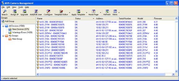
AXIS 215 PTZ Installation Guide                                                                Page 3

                              AXIS 215 PTZ
                            Installation Guide
This installation guide provides instructions for installing the AXIS 215 PTZ Network
Camera on your network. For all other aspects of using the product, please see the User’s
Manual, available on the CD included in this package, or from www.axis.com/techsup

Installation steps
1.   Check the package contents against the list below.

                                                                                                        ENGLISH
                                                                                                        ENGLISH
2.   Hardware overview. See page 4.
3.   Mount the hardware. See page 5.
4.   Assign an IP address. See page 10.
                                                                       Important!
5.   Set the password. See page 13.
                                                                       This product must be used in
                                                                       compliance with local laws
                                                                       and regulations.

     Package contents
Item                        Models/variants/notes

Network camera              •   AXIS 215 PTZ 50Hz (PAL)
                            •   AXIS 215 PTZ 60Hz (NTSC)
Power adapter               12V DC
Power adapter mains         •   Europe                         •   USA/Japan
cable                       •   UK                             •   Argentina
(country-specific)          •   Australia                      •   Korea
4-pin block connector       For connecting external devices to the I/O terminal connector
Drop ceiling mounting kit   1 inner bracket, 1 outer bracket
Plastic domes x 2           1 x for surface mounting
                            1 x for drop ceiling mounting
Screwdriver                 Resitorx T20
Screw kit                   •   1 x safety wire 1m (3.3 ft)    •   4 x screw M4x10
                            •   2 x plug 30x3.4-4mm            •   1 x screw M4x4
                            •   2 x screw ST4.2x38             •   2 x screw M4x10 resitorx
Template                    Use to mark positions for surface/drop ceiling mounting
CD                          AXIS Network Video Product CD, including product documentation,
                            installation tools and other software
Printed Materials           AXIS 215 PTZ Installation Guide (this document)
                            Axis Warranty Document
Page 4                        AXIS 215 PTZ Installation Guide

    Hardware overview
Surface mounted unit

  Drop ceiling mounted unit
AXIS 215 PTZ Installation Guide                                                         Page 5

Weights
       •    Camera: 0.60kg (1.32lb)
       •    Drop ceiling mount 0.54kg (1.19lb)
       •    Drop ceiling cover 0.12kg (0.26lb)
       •    Surface mount cover 0.13kg (0.29lb)
       •    Power adapter, including mains cable: 0.43kg (0.95lb)

Connectors & buttons
                                Audio in    Status, Network & Power
                                            Indicator LEDs (see         Power connector
                           Audio out                                    (see page 15)

                                                                                                 ENGLISH
                                            page 16)

                                                                                                 ENGLISH
                                                                            Control button
   Position 0°

           I/O terminal
           connector                                                  Network connector
           (see page 15)                                              (see page 15)

    Mounting

   !       IMPORTANT! - The AXIS 215 PTZ is designed for indoor and outdoor use. To
           use the camera outdoors, it must be installed in an approved outdoor housing.
           Please see www.axis.com for more information on outdoor housings.
           Do not use the camera’s dome bubble if it is to be installed in an outdoor
           housing as the use of two dome bubbles will reduce the image quality and
           cause image blurring.

The front position
The AXIS 215 PTZ can pan (swivel) ±180° from position 0°, i.e. the metal tab to the left of
the connectors, as illustrated above. This position can be thought of as the “front” of the
camera, and is the point to which the camera will return whenever it is (re)started.
Page 6 AXIS 215 PTZ Installation Guide
The AXIS 215 PTZ can be mounted in 2 different ways:
• Surface mounted on a hard ceiling, in which case the unit is fastened directly to the
ceiling material
• Recessed in a drop ceiling, which involves cutting a hole in the ceiling and using
the supplied drop ceiling mount
Surface mounting
If the required cabling is also surface mounted, the cables should enter via the removable
cable inlet on the large plastic dome cover.
1. Use the supplied template to mark
out the positions for the screws that
will fasten the camera to the ceiling.
If required, drill holes for the
supplied mounting plugs.
2. Use the 2 supplied 4.2x38 screws to
fasten the camera to the ceiling.
3. Connect the camera to the network
using a shielded network cable. 4.2x38mm
screw
4. Optionally connect external input/
output devices, e.g. alarm devices.
See page 15 for information on the
terminal connector pins.
5. Optionally connect an active speaker
and/or external microphone.
6. Connect the supplied indoor power
adapter to the power connector.
7. Using the supplied screwdriver, M4x10 resitorx Cable inlet
attach the large dome cover, using screw
the 2 M4x10 resitorx screws.
Notes:
• When power is applied, check that the
indicator LEDs indicate the correct
conditions. See the table on page 16 for
further details.
• The dome cover can be fitted with the
clear or the smoked plastic glass. See
Replacing the dome glass, on page 9.AXIS 215 PTZ Installation Guide Page 7
Drop ceiling mounting
1. If possible, remove the ceiling tile in which the drop ceiling mount is to be fitted.
2. Use the supplied template to mark the position for the hole in the ceiling tile. Remove the
protective paper, fix to ceiling tile and cut around the template.
Note: The combined weight of the camera, ceiling mount and cover is 1.26 kg (2.78 lb).
Check that the ceiling material is strong enough to support this weight. The
thickness of the ceiling should be 20-60mm (0.79”-2.36”).
3. Tilt and insert the outer ceiling bracket through the hole, and then pull it into place. The
bracket should be positioned so that the 3 vertical tabs point downwards in the hole.
ENGLISH
ENGLISH
Ceiling tile
Outer ceiling bracket Hole diameter 168-175mm
(6.6-6.9”)
4. Pull all of the required cables inner ceiling bracket
(network, power, etc) down through
the hole, ready for connection.
5. Align the camera’s screw holes with
the holes in the inner ceiling
bracket, and using the 4 supplied
M4x10 screws, mount the camera
on the inner ceiling bracket, as
illustrated here.
tabs
tabsPage 8 AXIS 215 PTZ Installation Guide
Note: It is important that the camera is centered within the inner ceiling bracket. The
distance between the camera and the rim of the inner ceiling bracket must be
equal on all sides. Measure an equal distance between the camera and the tabs on
either side of the inner ceiling bracket. Visually ensure the centering.
Camera must be centered within the inner ceiling bracket
distance between Distance between camera
camera and bracket and tab must be equal
tab
distance between
camera and bracket
tab
6. Adjust the length of the
supplied safety wire and attach
it to both the inner bracket and
the hard ceiling above the drop
ceiling.
7. Connect the camera to the
network using a shielded
network cable.
8. Optionally connect external
input/output devices, e.g.
alarm devices. See page 15 for
information on the terminal
connector pins.
9. Optionally connect an active
Safety wire
speaker and/or external Align slots
microphone. with screws M4x4 screw
10. Connect the supplied indoor
power supply to the power
connector on the camera.
11. Lift and turn the inner bracket
(with camera) so that the
screws on the outer bracket
enter the screw slots on the
inner bracket. Make sure that
the screws go all the way to
the back of the slots.AXIS 215 PTZ Installation Guide Page 9
12. Gently tighten the screws so that the ceiling tile is held between the inner and outer
brackets. Check that none of the cabling is trapped by the brackets.
Note: When power is applied, check that the indicator LEDs indicate the correct condi-
tions. See the table on page 16 for further details.
13. Using the supplied screwdriver, attach the smaller dome cover, using the 2 M4x10
resitorx screws.
ENGLISH
ENGLISH
M4x10 resitorx
screw
Replacing the dome glass
The dome cover can be fitted with the clear or the
smoked plastic glass. To switch covers, use a torque T6
screwdriver to remove the 4 fastening screws on the
inside of the dome, as shown here.
You are advised to take care when handling the plastic
glass, to avoid scratching it. The wearing of cotton
gloves is recommended.Page 10 AXIS 215 PTZ Installation Guide
Assign an IP address
Most networks today have a DHCP server that automatically assigns IP addresses to
connected devices. If your network does not have a DHCP server the AXIS 215 PTZ will use
192.168.0.90 as the default IP address.
If you would like to assign a static IP address the recommended method in Windows is either
AXIS IP Utility or AXIS Camera Management. Depending on the number of cameras you
wish to install, use the method that best suits your purpose.
Both of these free applications are available on the Axis Network Video Product CD supplied
with this product, or they can be downloaded from www.axis.com/techsup
Method Recommended for Operating system
AXIS IP Utility Single camera Windows
See page 11 Small installations
AXIS Camera Management Multiple cameras Windows 2000
See page 12 Large installations Windows XP Pro
Installation on a different subnet Windows 2003 Server
Notes:
• If assigning the IP address fails, check that there is no firewall blocking the operation.
• For other methods of assigning or discovering the IP address of the AXIS 215 PTZ, e.g. in other
operating systems, see page 14.AXIS 215 PTZ Installation Guide Page 11
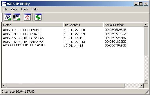
AXIS IP Utility - single camera/small installation
AXIS IP Utility automatically discovers and displays Axis devices on your network. The
application can also be used to manually assign a static IP address.
ENGLISH
ENGLISH
Note that the computer running AXIS IP Utility must be on the same network segment
(physical subnet) as the AXIS 215 PTZ.
Automatic discovery
1. Check that the AXIS 215 PTZ is connected to the network and that power has been
applied.
2. Start AXIS IP Utility.
3. When the camera appears in the window, double-click it to open its home page.
4. See page 13 for instructions on how to set the password.
Assign the IP address manually (optional)
1. Acquire an unused IP address on the same network segment as your computer.
2. Select the AXIS 215 PTZ in the list.
3. Click the button Assign new IP address to the selected device and enter the IP
address.
4. Click the Assign button and follow the instructions.
5. Click the Home Page button to access the camera’s web pages.
6. See page 13 for instructions on how to set the password.Page 12 AXIS 215 PTZ Installation Guide AXIS Camera Management - multiple cameras/large installations AXIS Camera Management can automatically discover multiple Axis devices, show connection status, manage firmware upgrades and set IP addresses. Assign an IP address in a single device 1. Select AXIS 215 PTZ in AXIS Camera Management and click the Assign IP button. 2. Select Assign the following IP address and enter the IP address, the subnet mask and default router the device will use. 3. Click the OK button. Assign IP addresses in multiple devices AXIS Camera Management speeds up the process of assigning IP addresses to multiple devices, by suggesting IP addresses from a specified range. 1. Select the devices you wish to configure (different models can be selected) and click the Assign IP button. 2. Select Assign the following IP address range and enter the range of IP addresses, the subnet mask and default router the devices will use. 3. Click the OK button.
AXIS 215 PTZ Installation Guide Page 13
Set the password
When accessing the AXIS 215 PTZ for the first
time, the ‘Configure Root Password’ dialog
will be displayed.
1. Enter a password and then re-enter it, to
confirm the spelling. Click OK.
2. Enter the user name root in the dialog as
requested.
Note: The default administrator user name
root cannot be deleted.
ENGLISH
ENGLISH
3. Enter the password as set above, and click OK. If the password is lost, the AXIS 215 PTZ
must be reset to the factory default settings. See page 16.
4. If required, click Yes to install AMC (AXIS Media Control), which allows viewing of the
video stream in Internet Explorer. You will need administrator rights on the computer to
do this.
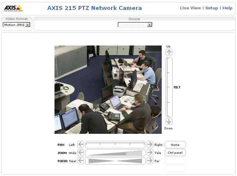
The Live View page of the AXIS 215 PTZ is displayed, with links to the Setup tools, which
allow you to customize the camera.
Setup - Provides all
the tools for config-
uring the camera to
requirements.
Help - Displays
online help on all
aspects of using
the camera.
Accessing the AXIS 215 PTZ from the Internet
Once installed, your AXIS 215 PTZ is accessible on your local network (LAN). To access the
camera from the Internet, network routers must be configured to allow incoming traffic,
which is usually done on a specific port. Please refer to the documentation for your router
for further instructions. For more information on this and other topics, visit the Axis Support
Web at www.axis.com/techsupPage 14 AXIS 215 PTZ Installation Guide
Other methods of setting the IP address
The table below shows the other methods available for setting or discovering the IP address.
All methods are enabled by default, and all can be disabled.
Use in operating Notes
system
UPnP™ Windows When enabled on your computer, the camera is automatically
(ME or XP) detected and added to “My Network Places.”
Bonjour MAC OSX Applicable to browsers with support for Bonjour. Navigate to the
(10.4 or later) Bonjour bookmark in your browser (e.g. Safari) and click on the
link to access the camera’s web pages.
AXIS Dynamic DNS All A free service from Axis that allows you to quickly and simply
Service install your camera. Requires an Internet connection with no
HTTP proxy. See www.axiscam.net for more information.
ARP/Ping All See below. The command must be issued within 2 minutes of
connecting power to the camera.
View DHCP server All To view the admin pages for the network DHCP server, see the
admin pages server’s own documentation.
Set the IP address with ARP/Ping
1. Acquire an IP address on the same network segment your computer is connected to.
2. Locate the serial number (S/N) on the AXIS 215 PTZ label.
3. Open a command prompt on your computer and enter the following commands:
Windows syntax Windows example
arp -s arp -s 192.168.0.125 00-40-8c-18-10-00
ping -l 408 -t ping -l 408 -t 192.168.0.125
UNIX/Linux/Mac syntax UNIX/Linux/Mac example
arp -s temp arp -s 192.168.0.125 00:40:8c:18:10:00
ping -s 408 temp
ping -s 408 192.168.0.125
4. Check that the network cable is connected to the camera and then start/restart the
camera, by disconnecting and reconnecting power.
5. Close the command prompt when you see ‘Reply from 192.168.0.125: ...’ or similar.
6. In your browser, type in http:// in the Location/Address field and press Enter
on your keyboard.
Notes:
• To open a command prompt in Windows: from the Start menu, select Run... and type cmd. Click OK.
• To use the ARP command on a Mac OS X, use the Terminal utility in Application > Utilities.AXIS 215 PTZ Installation Guide Page 15
Unit connectors
Network connector - RJ-45 Ethernet connector. Using shielded cables is recommended.
Power connector - DC connector 12V DC ±5%, max 14.5W. See product label for ±
connection.
Audio in - 3.5mm input for a mono microphone, or a line-in mono signal (left channel is
used from a stereo signal).
Audio out - Audio output (line level) that can be connected to a public address (PA) system
or an active speaker with a built-in amplifier. A pair of headphones can also be attached. A
stereo connector must be used for the audio out.
ENGLISH
ENGLISH
I/O terminal connector - Used in applications for e.g.
motion detection, event triggering, time lapse recording
and alarm notifications. It provides the interface to:
• 1 transistor output - For connecting external
devices such as relays and LEDs. Connected
devices can be activated by AXIS VAPIX API,
output buttons on the Live View page or by Pin 4 Pin 2
an Event Type. The output will show as active Pin 3 Pin 1
(shown under Event Configuration > Port
Status) if the alarm device is activated.
• 1 digital input - An alarm input for connecting devices that can toggle between
an open and closed circuit, for example: PIRs, door/window contacts, glass break
detectors, etc. When a signal is received the state changes and the input becomes
active (shown under Event Configuration > Port Status).
• Auxiliary power and GND
Function Pin number Notes Specifications
GND 1 Ground
12V DC 2 Can be used to power auxiliary equipment. Max load = 100mA
Power Note that the AXIS 215 PTZ itself cannot be
powered via the I/O terminal connector.
Digital Input 3 Connect to GND to activate, or leave float- Must not be exposed to
ing (or unconnected) to deactivate. voltages greater than
12V DC
Transistor 4 Uses an open-collector NPN transistor with Max load = 100mA
Output the emitter connected to the GND pin. If Max voltage = 24V DC
used with an external relay, a diode must be (to the transistor)
connected in parallel with the load, for pro-
tection against voltage transients.Page 16 AXIS 215 PTZ Installation Guide
Connection diagram
AXIS 215 PTZ
1
o
e.g. pushbutton
12V
max. 100mA 2o
z
3o
4
o
LED indicators
LED Color Indication
Network Green Steady for connection to a 100 Mbit/s network. Flashes for network activity.
Amber Steady for connection to 10 Mbit/s network. Flashes for network activity.
Unlit No network connection.
Status Green Steady green for normal operation.
Amber Steady during startup, during reset to factory default or when restoring settings.
Red Slow flash for failed upgrade.
Power Green Normal operation.
Amber Flashes green/amber during firmware upgrade.
Resetting to the Factory Default Settings
This will reset all parameters, including the IP address, to the factory default settings:
1. Disconnect power from the camera.
2. Press and hold the Control button and reconnect power.
3. Keep the Control button pressed until the Status indicator displays amber (this may take
up to 15 seconds), then release the button.
4. When the Status indicator displays green (which can take up to 1 minute) the process is
complete and the camera has been reset.
5. Re-assign the IP address, using one of the methods described in this document.
It is also possible to reset parameters to the original factory default settings via the web
interface. For more information, please see the online help or the user’s manual.AXIS 215 PTZ Installation Guide Page 17
Further information
The user’s manual is available from the Axis Web site at www.axis.com or from the Axis
Network Video Product CD supplied with this product.
Tip!
Visit www.axis.com/techsup to check if there is updated firmware available for your
AXIS 215 PTZ. To see the currently installed firmware version, see the Basic
Configuration web page in the product’s Setup tools.
ENGLISH
ENGLISHAXIS 215 PTZ Guide d’installation Page 19
AXIS 215 PTZ
Guide d'installation
Ce guide d'installation vous explique comment installer la caméra réseau AXIS 215 PTZ sur
votre réseau. Pour d'autres informations sur l'utilisation de ce produit, consultez le Manuel
de l'utilisateur, disponible sur le CD fourni ou sur www.axis.com/techsup.
Étapes de l'installation
1. Vérification du contenu de l'emballage à l'aide de la liste ci-dessous.
2. Présentation du matériel. Reportez-vous à la page 20.
3. Installation du matériel. Reportez-vous à la page 21.
4. Attribution d'une adresse IP. Reportez-vous à la
page 27. Important !
FRANCAIS
Ce produit doit être utilisé
5. Définissez le mot de passe. Reportez-vous à la
conformément aux lois et
page 30.
dispositions locales en
vigueur.
Contenu de l'emballage
Article Modèles/variantes/remarques
Caméra réseau • AXIS 215 PTZ 50 Hz (PAL)
• AXIS 215 PTZ 60 Hz (NTSC)
Câble d'alimentation 12 V CC
Câble d'alimentation sec- • Europe • États-Unis/Japon
teur • Royaume-Uni • Argentine
(dépend du pays) • Australie • Corée
Connecteur 4 broches Pour connecter des équipements externes au connecteur pour terminaux E/S
Montage sur faux-plafond 1 support intérieur, 1 support extérieur
2 dômes en plastique 1 pour le montage en saillie
1 pour le montage sur faux-plafond
Tournevis Resitorx T20
Kit de vis • 1 fil de sécurité 1m • 4 vis M4x10
• 2 chevilles 30 x 3,4-4 mm • 1 vis M4x4
• 2 vis ST4.2x38 • 2 vis M4x10 Resitorx
Modèle Utilisez le pour marquer les positions des éléments pour le montage en saillie/sur
faux-plafond
CD CD AXIS Network Video Product avec la documentation du produit, les outils
d'installation et d'autres logiciels
Documentation imprimée Guide d'installation de l'AXIS 215 PTZ (le présent document)
Document de garantie d'AxisPage 20 AXIS 215 PTZ Guide d’installation Présentation du matériel Dispositif de montage en saillie Dispositif de montage sur faux-plafond
AXIS 215 PTZ Guide d’installation                                                      Page 21

Poids
        •   Caméra 0,60 kg (1,32 livre)
        •   Support pour faux-plafond 0,54 kg (1,19 livre)
        •   Capot pour faux-plafond 0,12 kg (0,26 livre)
        •   Capot du support de montage en saillie 0,13 kg (0,29 livre)
        •   Câble d'alimentation, avec câble secteur: 0,43 kg (0,95 livre)

Connecteurs & boutons
                            Entrée audio    Témoins DEL de réseau,
                                            d'alimentation et d'état     Connecteur
                        Sortie audio                                     d'alimentation
                                            (reportez-vous à la
                                            page 34)                     (reportez-vous à la
                                                                         page 32)

                                                                             Bouton de
    Position 0°                                                              commande

                                                                                                 FRANCAIS
         Connecteur pour
         terminaux E/S                                                 Connecteur de
         (reportez-vous à                                              réseau
         la page 32)                                                   (reportez-vous à la
                                                                       page 32)

     Montage

!
    .IMPORTANT ! - L'AXIS 215 PTZ est conçue pour une utilisation intérieure et
    extérieure. Pour pouvoir être utilisée à l'extérieur, la caméra doit être placée dans un
    caisson de protection. Visitez le site www.axis.com pour plus d'informations.
    Ne pas utiliser la bulle du dôme si la caméra est installé dans un caisson de protection
    car l’utilisation de deux bulles réduit la qualité de l’image et donne une image trouble.

Position avant
L'AXIS 215 PTZ peut pivoter à ±180° à partir de la position 0°, c'est-à-dire à partir de la
languette en métal, comme indiqué dans l'illustration ci-dessus. Cette position peut être
considérée comme la face « avant » de la caméra. La caméra revient à cette position initiale à
chaque (re)démarrage.
Page 22 AXIS 215 PTZ Guide d’installation
L'AXIS 215 PTZ peut être montée de deux façons différentes:
• Montage en saillie, auquel cas l'appareil est fixé directement au matériau du
plafond
• Montage de l'appareil encastré sur un plafond, qui nécessite de percer un orifice
dans le plafond et d'utiliser le support pour faux-plafond fourni
Montage en saillie
Si les câbles nécessaires sont également en saillie, ils doivent passer par l'élément d'entrée de
câbles amovible sur le grand capot du dôme en plastique.
1. Utilisez le modèle fourni pour
marquer la position des vis qui
fixeront la caméra au plafond. Si
nécessaire, percez des trous pour les
chevilles de montage fournies.
2. Utilisez les 2 vis 4,2 x 38 fournies
pour fixer la caméra au plafond.
Vis de
3. Connectez la caméra à votre réseau à 4,2 x 38mm
l'aide d'un câble de réseau blindé.
4. Si vous le souhaitez, connectez des
dispositifs d'entrée/sortie externes,
par exemple des dispositifs d'alarme.
Reportez-vous à la page 32 pour plus
d'informations sur les broches du
connecteur pour terminaux.
Vis M4x10 Resitorx Entrée de câbles
5. Si vous le souhaitez, connectez un
haut-parleur actif et/ou un
microphone externe.
6. Branchez l'alimentation intérieure
fournie au connecteur
d'alimentation.
7. À l'aide du tournevis fourni et des 2
vis M4x10 Resitorx, fixez le grand
capot de dôme.
Remarques:
• Lorsque l'appareil est sous tension,
vérifiez que les témoins DEL indiquent les
conditions correctes. Pour plus d'informations, consultez le tableau à la page 34.
• Le capot du dôme peut être monté avec la vitre en plastique fumé ou transparent. Reportez-vous à la
Remplacement de la vitre du dôme à la page 26.AXIS 215 PTZ Guide d’installation Page 23
Montage sur un faux-plafond
1. Si possible, retirez la dalle de plafond à laquelle le support pour faux-plafond doit être
fixé.
2. Utilisez le gabarit fourni pour marquer la position du trou sur la dalle de plafond. Retirez
la protection, fixez le gabarit à la dalle de plafond et découpez autour du gabarit.
Remarque: Le poids total de la caméra et du support plafond est de 1,26 kg. Vérifiez que le
matériau du plafond est assez résistant pour supporter ce poids. L'épaisseur du plafond doit être
de 20-60 mm.
3. Inclinez le support de plafond extérieur et insérez-le dans le trou, puis mettez-le en
place. Le support doit être positionné de façon à ce que les 3 pattes verticales soient
orientées vers le bas du trou.
FRANCAIS
Dalle de plafond
Support de plafond extérieur Diamètre du trou
168-175 mm
4. Faites descendre l'ensemble des câbles
requis (réseau, alimentation, etc.) par le
trou. Le raccordement est alors possible.
5. À l'aide des 4 vis M4x10 fournies, montez
la caméra sur le support de plafond
intérieur, comme illustré ci-dessous.Page 24 AXIS 215 PTZ Guide d’installation
Remarque:
Il est important que la caméra soit centrée dans le support d´encastrement plafond. La distance
entre la caméra et le rebord du support d´encastrement plafond doit être egale de chaque coté.
Mersurez une distance égale entre la caméra et les fixations du support d´encastrement pla-
fond. Visuellement assurer le centrage.
la caméra doit être centrée dans le support d´encastrement plafond
Distance entre la caméra et le support Distance entre la camera et les fixations doit être égale
Fixation
Distance entre la caméra et le support
tabAXIS 215 PTZ Guide d’installation Page 25
6. Réglez la longueur du fil de
sécurité fourni et fixez-le au
support intérieur et au plafond
plein au-dessus du faux-
plafond.
7. Connectez la caméra à votre
réseau à l'aide d'un câble de
réseau blindé.
8. Si vous le souhaitez,
connectez des dispositifs
d'entrée/sortie externes, par
exemple des dispositifs
d'alarme. Reportez-vous à la
page 32 pour plus
Fil de sécurité
d'informations sur les broches Alignez les
du connecteur pour emplacements Vis M4x4
FRANCAIS
terminaux. par rapport
9. Si vous le souhaitez, aux vis
connectez un haut-parleur
actif et/ou un microphone
externe.
10. Branchez l'alimentation
intérieure fournie au
connecteur d'alimentation de
la caméra.
11. Soulevez et tournez le support intérieur (avec la caméra) de façon à ce que les vis situées
sur le support extérieur s'insèrent dans les emplacements prévus sur le support intérieur.
Veillez à ce que les vis soient parfaitement enfoncées dans leur emplacement.
12. Serrez délicatement les vis de façon à ce que la dalle de plafond soit maintenue entre les
supports intérieur et extérieur. Vérifiez que les supports ne bloquent aucun câble.
Remarque: Lorsque l'appareil est sous tension, vérifiez que les témoins DEL indiquent les
conditions correctes. Pour plus d'informations, consultez le tableau à la page 34.Page 26 AXIS 215 PTZ Guide d’installation
13. À l'aide du tournevis fourni et des 2 vis M4x10 Resitorx, fixez le petit capot de dôme.
Vis M4x10 Resitorx
Remplacement de la vitre du dôme
Le capot du dôme peut être monté avec la vitre
en plastique fumé ou transparent. Pour remplacer
le capot, utilisez un tournevis Torx T6. Retirez
les 4 vis situées à l'intérieur du dôme, comme
illustré ci-contre.
Manipulez la vitre en plastique avec précaution
pour ne pas la rayer. Pour cette manipulation, il
est recommandé de porter des gants en coton.AXIS 215 PTZ Guide d’installation Page 27
Attribution d'une adresse IP
Aujourd'hui, la plupart des réseaux comportent un serveur DHCP qui attribue
automatiquement des adresses IP aux dispositifs connectés. Si ce n'est pas le cas de votre
réseau, l'AXIS 215 PTZ utilisera l'adresse IP par défaut 192.168.0.90.
Si vous souhaitez affecter une adresse IP statique, sous Windows nous recommandons
l'utilisation de l'application AXIS IP Utility ou de l'application AXIS Camera Management.
Selon le nombre de caméras à installer, utilisez la méthode qui vous convient le mieux.
Ces deux applications gratuites sont disponibles sur le CD de la caméra vidéo réseau Axis
fourni avec ce produit. Vous pouvez également les télécharger à partir du site
www.axis.com/techsup.
Méthode Recommandée pour Système
d'exploitation
AXIS IP Utility Une seule caméra Windows
FRANCAIS
Voir page 27 Les petites installations
AXIS Camera Management Plusieurs caméras Windows 2000
Voir page 29 Les grandes installations Windows XP Pro
Installation sur un autre sous-réseau Windows 2003 Server
Remarques:
• En cas d'échec de l'attribution de l'adresse IP, vérifiez qu'aucun pare-feu ne bloque l'opération.
• Pour connaître les autres méthodes d'affectation ou de repérage de l'adresse IP de la caméra AXIS
215 PTZ, par exemple sur d'autres systèmes d'exploitation, reportez-vous à la page 31.
AXIS IP Utility - Une seule caméra/petite installation
L'utilitaire AXIS IP Utility détecte et affiche automatiquement les périphériques Axis de
votre réseau. Cette application sert également à définir manuellement une adresse IP
statique.
Notez que l'ordinateur exécutant l'application AXIS IP Utility doit se trouver sur le même
segment de réseau (sous-réseau physique) que la caméra AXIS 215 PTZ.Page 28 AXIS 215 PTZ Guide d’installation Détection automatique 1. Vérifiez que la caméra AXIS 215 PTZ est connectée au réseau et que l'alimentation est activée. 2. Démarrez AXIS IP Utility. 3. Lorsque l'icône de la caméra apparaît dans la fenêtre, double-cliquez dessus pour ouvrir la page d'accueil correspondante. 4. Consultez la page 30 pour savoir comment définir le mot de passe. Définissez manuellement l'adresse IP (optionnel) 1. Trouvez une adresse IP inutilisée sur le même segment de réseau que celui de votre ordinateur. 2. Sélectionnez le nom abrégé du produit dans la liste. 3. Cliquez sur le bouton Paramétrer une nouvelle adresse IP de l'outil sélectionné. 4. Cliquez sur le bouton Paramétrer et suivez les instructions. 5. Cliquez sur le bouton Page d'accueil pour accéder aux pages Web de la caméra. 6. Consultez la page 30 pour savoir comment définir le mot de passe.
AXIS 215 PTZ Guide d’installation                                                     Page 29

AXIS Camera Management - Plusieurs caméras/grandes installations
AXIS Camera Management peut détecter automatiquement plusieurs dispositifs Axis,
afficher les états de connexion, gérer les mises à niveau du microcode et définir les adresses
IP.

                                                                                                 FRANCAIS
Détection automatique
1. Vérifiez que la caméra est connectée au réseau et que l'alimentation est activée.
2. Démarrez AXIS Camera Management. Double-cliquez sur l'icône de l'AXIS 215 PTZ
   lorsqu'elle apparaît dans la fenêtre de façon à ouvrir la page d'accueil.
3. Consultez la page 30 pour savoir comment définir le mot de passe.

Attribuer une adresse IP à un seul dispositif
1. Sélectionnez AXIS 215 PTZ dans l'application AXIS
   Camera Management, puis cliquez sur le bouton Assign
    IP (Affecter une IP).
2. Sélectionnez Assign the following IP address (Affecter
   l’adresse IP suivante) et saisissez la plage d’adresse IP, le
   masque de sous-réseau et le routeur par défaut que le
   dispositif utilisera.
3. Cliquez sur le bouton OK.

Attribuer des adresses IP à plusieurs dispositifs
AXIS Camera Management accélère le processus
d'affectation d'adresses IP sur plusieurs appareils en
suggérant les adresses IP parmi une plage spécifiée.
1. Sélectionnez les appareils à configurer (il peut s'agir de
   plusieurs modèles), puis cliquez sur le bouton Assign IP
   (Affecter une adresse IP).
Page 30 AXIS 215 PTZ Guide d’installation
2. Sélectionnez Assign the following IP address range (Affecter la plage d’adresses IP
suivante) et saisissez la plage d'adresses IP, le masque de sous-réseau et le routeur par
défaut que les dispositifs utiliseront.
3. Cliquez sur le bouton OK.
Définition du mot de passe
Si vous accédez à la caméra AXIS 215 PTZ
pour la première fois, la boîte de dialogue
Configure Root Password (Configurer le mot
de passe root) s'affiche.
1. Entrez un mot de passe et entrez-le une
seconde fois pour en confirmer
l'orthographe. Cliquez sur OK.
2. Saisissez le nom d'utilisateur root dans la
boîte de dialogue lorsque vous y êtes invité.
Remarque : le nom d'utilisateur par défaut de l'administrateur, à savoir root, ne peut pas
être supprimé.
3. Entrez le mot de passe comme expliqué ci-dessus, puis cliquez sur OK. Si vous avez
oublié votre mot de passe, vous devrez rétablir les paramètres d'usine par défaut de la
caméra AXIS 215 PTZ. Reportez-vous à la page 35.
4. Si nécessaire, cliquez sur Yes (Oui) pour installer AMC (Axis Media Control) afin de
pouvoir visualiser le flux vidéo dans Internet Explorer. Pour ce faire, vous devrez être
connecté à votre ordinateur avec les droits d'administrateur.
La page Live View (Vidéo en direct) de la caméra AXIS 215 PTZ s'affiche, avec des liens vers
les outils de configuration pour adapter la caméra à vos besoins.
Setup (Configuration): con-
tient tous les outils néces-
saires pour adapter la
caméra à vos besoins.
Help (Aide):
affiche une aide
en ligne sur l'util-
isation de la
caméra.
Accès à la caméra AXIS 215 PTZ depuis InternetAXIS 215 PTZ Guide d’installation Page 31
Une fois installée, votre caméra AXIS 215 PTZ est accessible depuis votre réseau local (LAN).
Pour accéder à la caméra depuis Internet, vous devez configurer les routeurs réseau afin
d'autoriser l'entrée de données, ce qui se fait généralement sur un port spécifique. Consultez
la documentation de votre routeur pour obtenir davantage d'instructions. Pour de plus
amples informations, visitez le site de support d'Axis à l'adresse
www.axis.com/techsup.
Autres méthodes de définition de l'adresse IP
Le tableau ci-dessous indique les autres méthodes permettant de définir ou de déterminer
l'adresse IP. Toutes les méthodes sont activées par défaut et désactivables.
Système d'exploitation Remarques
UPnP™ Windows Lorsque la caméra est activée sur votre ordinateur, elle est détectée et
(ME ou XP) ajoutée automatiquement au dossier Favoris réseau.
Bonjour MAC OS X Applicable aux navigateurs prenant en charge Bonjour. Accédez au
FRANCAIS
(10.4 ou version raccourci de Bonjour dans votre navigateur (par exemple, Safari), puis
ultérieure) cliquez sur le lien pour accéder aux pages Web de la caméra.
AXIS Dynamic Tous Service Axis gratuit vous permettant d'installer rapidement votre
DNS Service caméra en toute simplicité. Nécessite une connexion Internet sans
proxy HTTP Pour plus d'informations, visitez le site www.axiscam.net.
ARP/Ping Tous Reportez-vous aux instructions ci-dessous. La commande doit être
saisie dans les 2 minutes suivant la connexion de l'alimentation à la
caméra.
Serverur DHCP Tous Pour consulter les pages administratives du serveur DHCP réseau,
reportez-vous à la documentation du serveur.
Définition de l'adresse IP à l'aide d'ARP/Ping
1. Trouvez une adresse IP sur le même segment de réseau que celui de votre ordinateur.
2. Repérez le numéro de série (S/N) sur l'étiquette de la caméra AXIS 215 PTZ.
3. Ouvrez une invite de commande sur votre ordinateur et entrez les commandes suivantes:
Syntaxe pour Windows Exemple pour Windows
arp -s arp -s 192.168.0.125 00-40-8c-18-10-00
ping -l 408 -t ping -l 408 -t 192.168.0.125
Syntaxe pour UNIX/Linux/Mac Exemple pour UNIX/Linux/Mac
arp -s arp -s 192.168.0.125 00:40:8c:18:10:00
temp temp
ping -s 408 ping -s 408 192.168.0.125
4. Vérifiez que le câble réseau est connecté à la caméra, puis démarrez/redémarrez cette
dernière en débranchant, puis en rebranchant l'alimentation.
5. Fermez la commande d'invite quand vous voyez « Reply from 192.168.0.125: ... »
(Réponse de 192.168.0.125 : ...) ou un message similaire.Page 32 AXIS 215 PTZ Guide d’installation
6. Dans votre navigateur, tapez http:// dans le champ Emplacement/Adresse,
puis appuyez sur Entrée sur le clavier.
Remarques:
• Pour ouvrir une invite de commande sous Windows : dans le menu Démarrer, sélectionnez Exécuter…
et tapez cmd (ou commande sous Windows 98/ME). Cliquez sur OK.
• Pour utiliser la commande ARP sur Mac OS X, utilisez l'utilitaire Terminal dans Application >
Utilitaires.
Connecteurs de l'unité
Connecteur de réseau - Connecteur Ethernet RJ-45. Il est recommandé d'utiliser des câbles
blindés.
Connecteur d’alimentation - Miniconnecteur CC. 12 V CC +-5%, jusqu'à 14.5 W. Reportez-
vous à l'étiquette du produit pour connaître la connexion ±.
Entrée audio - 3.5 mm entrée pour microphone mono , ou ligne entrée en signale mono (le
canal à gauche est utilisé pour le signal stéréo.
Sortie audio - sortie audio qui peut être connecté à un système d'adresse publique (PA) ou
haut parleur actif avec amplificateur intégré. Une paire d'écouteur peut être aussi connecté.
Un connecteur stéréo doit être utilisé pour la sortie audio.
Connecteur pour terminaux E/S - Utilisé dans les
applications, par exemple pour la détection de
mouvement, le déclenchement d'événements,
l'enregistrement à intervalles, les notifications d'alarme,
etc. Il sert d'interface aux éléments suivants:
• 1 sortie transistor: permet de connecter des
dispositifs externes, comme des relais ou Broche 4 Broche 2
DELs. Les dispositifs connectés peuvent être Broche 3 Broche 1
activés à l'aide d’AXIS VAPIX API, des bou-
tons de sortie sur la page Live View (Vidéo en direct) ou à l'aide d'un type
d'événement. La sortie est considérée comme étant active (Event Configuration
(Configuration d'événement) > Port Status (État du port)) si le dispositif
d'alarme est activé.
• 1 entrée numérique: entrée d'alarme utilisée pour connecter des dispositifs pou-
vant passer d'un circuit ouvert à un circuit fermé, par exemple : les détecteurs
infrarouge passifs, les contacts de porte/fenêtre, les détecteurs de bris de verre,
etc. Lorsqu'un signal est reçu, l'état change et l'entrée devient active (elle appa-
raît sous Event Configuration (Configuration d'événement) > Port Status (État
du port)).
• Alimentation auxiliaire et mise à la terre.AXIS 215 PTZ Guide d’installation Page 33
Fonction Numéro de Remarques Spécifications
broche
GND 1 Terre.
Alimentation 2 Cette broche peut également servir Intensité maximale: 100
auxiliaire à alimenter le matériel auxiliaire. mA.
12V DC
Entrée 3 Connectez-la au GND pour l'activer Ne doit pas être exposée à
numérique ou laissez-la flotter (ou décon- une tension supérieure à
nectée) pour la désactiver. 12 V DC
Sortie tran- 4 Utilise un transistor NPN à collect- Charge maximale = 100mA
sistor eur ouvert avec émetteur connecté Tension maximale = 24V
au contact à la masse. En cas d'util- DC
isation avec un relais externe, une (en entrée)
diode doit être connectée en par-
allèle avec la charge, comme pro-
tection contre les tensions
transitoires.
FRANCAISPage 34 AXIS 215 PTZ Guide d’installation
Diagramme de connexion
AXIS 215 PTZ
1
o Par exemple, un bouton
de commande
12V
max. 100mA 2o
z
3o
4
o
Témoins DEL
DEL Couleur Indication
Réseau Vert Continu en cas de connexion à un réseau 100 Mbits/s. Clignote en cas d'activité
réseau.
Orange Continu en cas de connexion à un réseau 10 Mbits/s. Clignote en cas d'activité
réseau.
Éteint Pas de connexion à réseau.
État Vert Vert continu en cas de fonctionnement normal.
Orange En continu pendant le démarrage, la réinitialisation des valeurs d'usine ou la res-
tauration des paramètres.
Rouge Clignote lentement en cas d'échec de la mise à niveau.
Alimen- Vert Fonctionnement normal.
tation Orange Clignote en vert/orange pendant la mise à niveau du microprogramme.AXIS 215 PTZ Guide d’installation Page 35
Rétablissement des paramètres d'usine par défaut
Procédez comme suit pour revenir aux paramètres par défaut définis en usine et réinitialiser
l'adresse IP:
1. Débranchez l'alimentation de la caméra.
2. Maintenez le bouton de commande enfoncé et rebranchez l'alimentation.
3. Maintenez le bouton enfoncé jusqu'à ce que le témoin DEL d'état passe à l'orange (cela
peut prendre 15 secondes), puis relâchez le bouton.
4. Lorsque le témoin DEL d'état émet une lumière verte (ce qui peut prendre 1 minute), les
paramètres par défaut de la caméra ont été rétablis.
5. Réinstallez la caméra AXIS 215 PTZ à l'aide de l'une des méthodes décrites dans ce
document.
Il est également possible de rétablir les paramètres usine par défaut d'origine via l'interface
Web. Pour plus d'informations, reportez-vous à l'aide en ligne ou au Manuel de l'utilisateur.
FRANCAIS
Plus d'informations
Le Manuel de l'utilisateur est disponible sur le site Web d'Axis, www.axis.com, ou sur le CD
du produit vidéo réseau Axis fourni avec la caméra.
Conseil:
Visitez le site www.axis.com/techsup pour vérifier si des microcodes mis à jour sont
disponibles pour votre caméra AXIS 215 PTZ. Pour connaître la version du
microcode actuellement installée, reportez-vous à la page Web Basic Configuration
(Configuration de base) dans les outils de configuration du produit.AXIS 215 PTZ Installationsanleitung Seite 37
AXIS 215 PTZ
Installationsanleitung
In dieser Anleitung wird die Installation der AXIS 215 PTZ-Netzwerkkamera in einem
Netzwerk beschrieben. Alle weiteren Hinweise zur Verwendung des Produkts finden Sie im
Benutzerhandbuch, das auf der mitgelieferten CD enthalten ist und auf unserer Webseite
unter www.axis.com/techsup zur Verfügung steht.
Installationsschritte Wichtiger Hinweis!
1. Prüfen Sie, ob alle in der nachfolgenden Liste auf- Verwenden Sie dieses Produkt
geführten Komponenten vorhanden sind. nur gemäß den geltenden
2. Hardwareübersicht (siehe page 38). rechtlichen Bestimmungen.
3. Hardware installieren (siehe page 39).
4. IP-Adresse zuweisen (siehe page 44).
5. Kennwort festlegen (siehe page 48).
Lieferumfang
DEUTSCH
Komponente Modelle/Varianten/Anmerkungen
Netzwerkkamera • AXIS 215 PTZ 50 Hz (PAL)
• AXIS 215 PTZ 60 Hz (NTSC)
Netzteil 12 V Gleichstrom
Netzkabel für Netzteil • Europa • USA/Japan
(landesspezifisch) • Großbritannien • Argentinien
• Australien • Korea
4-poliger Anschlussblock Zum Anschluss externer Geräte an den E/A-Anschluss
Montagesatz für die Befestigung 1 innere Halterung, 1 äußere Halterung
an einer Unterhangdecke
2 Kunststoffhauben 1 x für direkte Deckenbefestigung
1 x für die Befestigung an einer Unterhangdecke
Schraubendreher Resitorx T20
Schraubensatz • 1 x Sicherungskabel 1 m • 4 x Schrauben M4x10
• 2 x Dübel 30 × 3,4–4 mm • 1 x Schraube M4x4
• 2 x Schrauben ST 4,2 × 38 • 2 x Schrauben M4x10 Resitorx
Vorlage Zur Positionsmarkierung bei der direkten Deckenbefestigung bzw. der
Befestigung an der Unterhangdecke
CD CD für AXIS-Netzwerkvideoprodukte einschließlich Produktdokumenta-
tion, Installationstools und anderer Software
Gedruckte Dokumente AXIS 215 PTZ Installationshandbuch (dieses Dokument)
Axis-GarantieerklärungSeite 38 AXIS 215 PTZ Installationsanleitung
Hardwareübersicht
Direkte Deckenbefestigung
Befestigung an UnterhangdeckeAXIS 215 PTZ Installationsanleitung Seite 39
Gewichtsangaben
• Kamera 0,60 kg
• Unterhangdeckenhalterung 0,54 kg
• Abdeckung für Unterhangdeckenbefestigung 0,12 kg
• Abdeckung für direkte Deckenbefestigung 0,13 kg
• Netzteil mit Netzkabel 0,43 kg
Anschlüsse und Tasten
Audio-Eingang Status-, Netzwerk- und
Betriebsanzeige (siehe Stromanschluss
Audio-Ausgang (siehe page 50)
page 52)
Steuertaste
Position 0°
E/A-Anschluss
(siehe page 50) Netzwerkanschluss
(siehe page 50)
DEUTSCH
Hardware installieren
!
WICHTIG! - Die AXIS 215 PTZ ist für die Verwendung sowohl in Innenräumen
als auch für den Außeneinsatz geeignet. Um die Kamera im Freien zu verwenden,
muss sie in einem zugelassenen Außengehäuse installiert werden. Auf unserer
Homepage unter www.axis.com finden Sie weitere Informationen über
Außengehäuse.
Benutzen Sie die Kamerakuppel nicht wenn die Kamera in einem Außengehäuse
montiert wird, da zwei Kuppeln die Bildqualität reduzieren und Unschärfen
erzeugen.
Die Ausgangsposition
Die AXIS 215 PTZ kann aus der Ausgangsposition 0° (am Metallstreifen links von den
Anschlüssen, siehe Abbildung) um ±180° geschwenkt werden. Diese Position kann als
"Vorderseite" der Kamera angesehen werden. Nach einem Neustart schwenkt die Kamera
stets in diese Position zurück.Seite 40 AXIS 215 PTZ Installationsanleitung
Die AXIS 215 PTZ kann auf zwei Arten angebracht werden:
• An einer Massivdecke, wobei das Gehäuse direkt an der Decke befestigt wird.
• Versenkt in eine Unterhangdecke, wobei ein Loch in die Decke geschnitten und
das Kameragehäuse mit der mitgelieferten Halterung eingepasst wird.
Direkte Deckenbefestigung
Falls die für die Kamera erforderliche Verkabelung ebenfalls an der Zimmerdecke angebracht
werden muss, sollten die Kabel erst durch die Kabelöffnung der abnehmbaren
Kunstoffkuppelhaube geführt werden.
1. Verwenden Sie die mitgelieferte Vorlage,
um die Position der Schrauben für die
Befestigung der Kamera zu markieren.
Falls erforderlich, bohren Sie Löcher in die
Decke, und setzen Sie die Dübel ein.
2. Befestigen Sie die Kamera mit Hilfe der
beiden mitgelieferten 4,2×38-Schrauben 4,2×38 mm
an der Zimmerdecke. Schraube
3. Verbinden Sie die Kamera über ein
abgeschirmtes Netzwerkkabel mit dem
Netzwerk.
4. Sie können zusätzlich externe Ein- und
Ausgabegeräte wie Alarmanlagen Kabelöffnung
anschließen. Informationen zur
Anschlussbelegung finden Sie auf
page 50.
5. Sie können zusätzlich einen
Aktivlautsprecher und/oder ein externes
Mikrofon anschließen. M4x10
Resitorx-
6. Schließen Sie das mitgelieferte Netzteil für Schraube
Innenräume an den Stromanschluss an.
7. Befestigen Sie die große Kuppelhaube mit
den mitgelieferten M4x10 Resitorx-
Schrauben und dem im Lieferumfang
enthaltenen Schraubendreher.
Notes:
• Nachdem Sie die Stromversorgung angeschlossen haben, überprüfen Sie, ob die LED-Anzeigen den
Betriebszustand korrekt wiedergeben. Weitere Informationen finden Sie in der Tabelle auf page 52.
• Die Kuppelhaube kann mit der Klarsicht- oder der Rauchglas-Kunststoffabdeckung verkleidet
werden. (siehe Kuppelabdeckung wechseln, on page 44).
• Benutzen Sie die Kamerakuppel nicht wenn die Kamera in einem Außengehäuse montiert wird, da
zwei Kuppeln die Bildqualität reduzieren und Unschärfen erzeugen.AXIS 215 PTZ Installationsanleitung Seite 41
Befestigung an einer Unterhangdecke
1. Entfernen Sie wenn möglich die Deckenplatte, an der die Unterhangdeckenhalterung
befestigt werden soll.
2. Markieren Sie mit Hilfe der mitgelieferten Schablone die Position für die Öffnung in der
Deckenplatte. Entfernen Sie das Schutzpapier der Schablone, und bringen Sie sie an der
Deckenplatte an. Schneiden Sie um die Schablone herum die Öffnung aus.
Hinweis: Das Gesamtgewicht von Kamera und Deckenhalterung beträgt 1,26 kg. Über-
prüfen Sie, ob die Decke stabil genug ist, um dieses Gewicht tragen zu können. Die Decke
sollte zwischen 20 und 60 mm dick sein.
3. Setzen Sie die äußere Deckenhalterung schräg in die Öffnung ein, und bringen Sie sie
anschließend in Position. Dabei müssen die drei senkrechten Laschen nach unten zeigen.
Deckenplatte
DEUTSCH
Durchmesser der Öffnung
Äußere Deckenhalterung 168-175 mmSeite 42 AXIS 215 PTZ Installationsanleitung
4. Ziehen Sie alle erforderlichen,
anschlussfertigen Kabel (Netzwerk, Strom
usw.) durch die Öffnung.
5. Befestigen Sie die Kamera wie dargestellt
mit den vier M4x10-Schrauben an der
inneren Deckenhalterung.
Hinweis: Es ist wichtig, dass die Kamera in der inneren Deckenhalterung zentriert ver-
baut ist. Die Abstände zwischen der Kamera und dem Rand der inneren Deckenhalterung
müssen auf allen Seiten gleich sein. Messen Sie den gleichen Abstand zwischen der Kam-
era und den Laschen an beiden Seiten der inneren Deckenhalterung. Bitte überprüfen Sie
die Zentrierung optisch.
Die Kamera muss innerhalb der inneren Deckenhalterung zentriert werden
Abstände zwischen Kamera
Abstand zwischen Kamera und Halterung und Laschen müssen gleich sein
Lasche
Abstand zwischen Kamera
und Halterung
LascheAXIS 215 PTZ Installationsanleitung Seite 43
6. Passen Sie die Länge des
mitgelieferten
Sicherungskabels an, und
befestigen Sie es an der
inneren Halterung und an der
Massivdecke, die sich über der
Unterhangdecke befindet.
7. Verbinden Sie die Kamera über
ein geschirmtes Netzwerkkabel
mit dem Netzwerk.
8. Sie können zusätzlich externe
Ein- und Ausgabegeräte wie
Alarmanlagen anschließen.
Informationen zur
Sicherungskabel
Anschlussbelegung finden Sie Aussparungen
auf page 50. und Schrauben M4x4-Schraube
9. Sie können zusätzlich einen ausrichten
Aktivlautsprecher und/oder ein
externes Mikrofon anschließen.
10. Schließen Sie das mitgelieferte
Netzteil an den Stromanschluss
DEUTSCH
der Kamera an.
11. Heben Sie die innere Halterung
mit der Kamera an, und drehen
Sie sie so, dass die Schrauben
an der äußeren Halterung in die Aussparungen der inneren Halterung eingeführt werden.
Dabei müssen die Schrauben an das Ende der Schlitze stoßen.
12. Ziehen Sie die Schrauben vorsichtig fest, sodass die Deckenplatte zwischen der inneren
und der äußeren Halterung gehalten wird. Achten Sie darauf, dass kein Kabel zwischen
den Halterungen eingeklemmt ist.
Hinweis: Nachdem Sie die Stromversorgung angeschlossen haben, überprüfen Sie, ob
die LED-Anzeigen den Betriebszustand korrekt wiedergeben. Weitere Informationen fin-
den Sie in der Tabelle auf page 52.Seite 44 AXIS 215 PTZ Installationsanleitung
13. Befestigen Sie die kleinere Kuppelhaube mit den mitgelieferten M4x10 Resitorx-
Schrauben und dem im Lieferumfang enthaltenen Schraubendreher.
M4x10
Resitorx-Schraube
Kuppelabdeckung wechseln
Die Kuppelhaube kann mit der Klarsicht- oder
der Rauchglas-Kunststoffabdeckung verkleidet
werden. Verwenden Sie zum Wechseln der
Abdeckungen einen Torx T6-Schraubendreher,
um die 4 Schrauben innerhalb der Kuppel wie in
der Abbildung gezeigt zu entfernen.
Achten Sie beim Umgang mit der
Kunststoffabdeckung darauf, dass diese nicht
durch Kratzer beschädigt wird. Um
Beschädigungen auszuschließen, wird das Tragen
von Baumwollhandschuhen empfohlen.
IP-Adresse zuweisenAXIS 215 PTZ Installationsanleitung Seite 45
In den meisten Netzwerken ist heutzutage ein DHCP-Server eingebunden, der
angeschlossenen Geräten automatisch IP-Adressen zuweist. Wenn Ihr Netzwerk über keinen
DHCP-Server verfügt, wird für die AXIS 215 PTZ die Standard-IP-Adresse 192.168.0.90
verwendet.
Zum Zuweisen einer statischen IP-Adresse stehen unter Windows die Programme AXIS IP
Utility und AXIS Camera Management zur Verfügung. Verwenden Sie die Methode, die für
die gewünschte Anzahl der zu installierenden Kameras geeignet ist.
Beide Anwendungen stehen kostenlos auf der mitgelieferten CD für Axis-
Netzwerkvideoprodukte zur Verfügung oder können unter www.axis.com/techsup
heruntergeladen werden.
Methode Empfohlen für Betriebssystem
AXIS IP Utility Einzelne Kamera Windows
Siehe page 45 Kleine Installationen
AXIS Camera Management Mehrere Kameras Windows 2000
Siehe page 47 Große Installationen Windows XP Pro
Installation in einem anderen Sub- Windows 2003 Server
netz
Notes:
DEUTSCH
• Falls Sie die IP-Adresse nicht zuweisen können, müssen ggf. die Einstellungen der Firewall überprüft
werden.
• Weitere Informationen zu alternativen Methoden zum Festlegen der IP-Adresse der AXIS 215 PTZ
(z. B. in anderen Betriebssystemen) finden Sie auf page 49.
AXIS IP Utility - Einzelne Kamera/kleine Installation
AXIS IP Utility erkennt automatisch im Netzwerk vorhandene Axis-Geräte und zeigt diese
an. Die Anwendung kann außerdem zur manuellen Zuweisung einer statischen IP-Adresse
verwendet werden.
Beachten Sie, dass sich die AXIS 215 PTZ und der Computer, auf dem AXIS IP Utility
ausgeführt wird, im gleichen Netzwerksegment (d. h. physischen Subnetz) befinden müssen.You can also read