Sunred Gas Heater SFT15 Series - Vuurkorfwinkel.nl
←
→
Page content transcription
If your browser does not render page correctly, please read the page content below
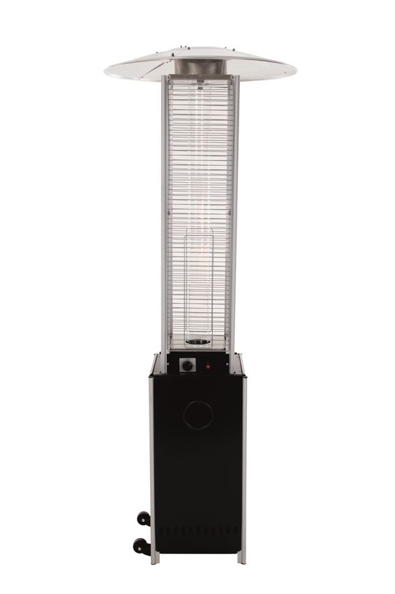
Sunred Gas Heater
                                 SFT15 Series

EN   PATIO HEATER                                      0063/19
NL   TERRASVERWARMER

DE   TERRASSENHEIZSTRAHLER                          2 years warranty
FR   RADIATEUR DE TERRASSE         MADE IN P.R.C.

                                                          V1_CN_250719
EN

                     User instructions - please keep for future references

   EN Gas Patio Heater

WARNING
Use in closed spaces can be
dangerous and is FORBIDDEN

WARNING
Please read the manual
before usage

IMPORTANT
Carefully remove the
packaging before use, but
keep the safety instruments.
These are part of the pro-
duct. Please note all safety
warnings mentioned in this
manual.
Read the instructions in their
entirety and keep them for
future reference.
These must be stored with
the product. This product is
for household use and may
not be used for commercial
or contractual purposes.

                                                                                  1
EN
WARNING SAFETY RULES
PLEASE READ THE FOLLOWING SAFETY RULES PRIOR TO OPERATION OF THE HEATER
FOR YOUR SAFETY
If you smell gas:
1. Shut off gas to the appliance.
2. Extinguish any open flame.
3. If odor continues, immediately call your gas supplier or your fire department.
FOR YOUR SAFETY
1. Do not store or use gasoline or other flammable vapors and liquids in the vicinity of this or any other appliance.
2. An LP cylinder not connected for use shall not be stored in the vicinity of this or any other appliance.
WARNING
1) For use outdoors or in amply ventilated areas.
2) An amply ventilated area must have a minimum of 25 % of the surface area open.
3) The surface area is the sum of the walls surface. (See figure 2)
Fig. 2
WARNING
Improper installation, adjustment, alteration, service or maintenance can cause injury or
property damage. Read the installation, operating and maintenance instructions thoroughly before installing or servicing this equip-
ment.
WARNING
This appliance must be installed and the gas cylinder stored in accordance with the regulations in force;
• Do not obstruct the ventilation holes of the cylinder housing;
• Do not move the appliance when in operation;
• Shut off the valve at the gas cylinder or the regulator before moving the appliance;
• The tubing or the flexible hose must be changed within the prescribed intervals;
• Use only the type of gas and the type of cylinder specified by the manufacturer;
The LP tank used with your patio heater must meet the following requirements:
Purchase LP tanks only with these required measurements: (30.5cm) (diameter) x 57.1 cm) (tall) with 23kg capacity maximum.
• In case of violent wind particular attention must be taken against tilting of the appliance;
2EN
Table of contents
Caution 43
Heater Stand and Location 44
Gas Requirements 44
Leakage Test 45
Operation and Storage 48
Cleaning and Care 46
Parts and Specifications 49
Assembly Parts and Procedures 48
Problems Check List 57
3EN
CAUTION
PLEASE READ CAREFULLY THE FOLLOWING SAFETY GUIDELINES BEFORE OPERATION
Do not use the patio heater for indoors, as it may cause personal injury or property damage.
This outdoor heater is not intended to be installed on recreational vehicles and/or boats. Installation and repair should
be done by a qualified service person.
Improper installation, adjustment, alteration can cause personal injury or property damage. Do not attempt to alter the unit in
any manner.
Never replace or substitute the regulator with any regulator other than the factory-suggested replacement.
Do not store or use gasoline or other flammable vapors or liquids in the heater unit.
The whole gas system, hose, regulator, pilot or burner should be inspected for leaks or damage before use, and at least annually
by a qualified service person.
All leak tests should be done with a soap solution. Never use an open flame to check for leaks. Do not use the heater until all
connections have been leak tested.
Turn off the gas valve immediately if smell of gas is detected. Turn Cylinder Valve OFF. If leak is at Hose/Regulator connection:
tighten connection and perform another leak test. If bubbles continue appearing should be returned to hose’s place of purchase.
If leak is at Regulator/Cylinder Valve connection: disconnect, reconnect, and perform another leak check. If you continue to see
bubbles after several attempts, cylinder valve is defective and should be returned to cylinder’s place of purchase.
Do not transport heater while it’s operating.
Do not move the heater after it has been turned off until the temperature has cooled down. Keep the ventilation opening of the
cylinder enclosure free and clear of debris.
Do not paint the radiant screen, control panel or top canopy reflector.
Control compartment, burner and circulation air passageways of the heater must be kept clean. Frequent cleaning may be requi-
red as necessary.
The LP tank should be turned off when the heater is not in use. Check the heater immediately if any of the following occurs:
- The heater does not reach temperature.
- The burner makes popping noise during use (a slight noise is normal when the burner is extinguished).
- Smell of gas in conjunction with extreme yellow tipping of the burner flames.
WARNING
The user assumes all risks of assembling and operating gas heater. Not heeding the warnings and instructions of this manual can result in
sever bodily harm, death or material damage. If you don’t read this user manual or if you cannot fully understand it, please ask your spe-
cialized dealer. The manufacturer or supplier assumes no liability for negligent user behavior.
WARNING
When not heeding the instructions and information in this manual or in case of improper usage outside of the intended usage purposes,
4EN
CAUTION
PLEASE READ CAREFULLY THE FOLLOWING SAFETY GUIDELINES BEFORE OPERATION
• The LP regulator/hose assembly must be located out of pathways where people may trip over it or in area where the hose
will not be subject to accidental damage.
• Any guard or other protective device removed for servicing the heater must
be replaced before operating
• the heater. Adults and children should stay away from high temperature
surface to avoid burns or clothing ignition.
• Children should be carefully supervised when they are in the area of the
heater.
• Clothing or other flammable materials should not be hung on the heater or
placed on or near the heater.
• To change the gas cylinder in a amply ventilated area, away from any ignition
• source (candle, cigarettes, other flame producing appliances, ...);
• To check that the regulator seal is correctly fitted and able to fulfill its
function showed as photo right; Seal
• To not obstruct the ventilation holes of the cylinder housing; Hose
• To close the gas supply at the valve of the gas cylinder or the regulator after
Regulator
use;
• In the event of gas leakage, the appliance shall not be used or if alight, the Cylinder
gas supply shall be shut off and the appliance shall be investigated and
rectified before it is used again;
• To check the hose at least once per month, each time the cylinder is
changed, or each time before long time no use.
• If it shows signs of cracking, splitting or other deterioration it shall be
exchanged for new hose of the same length and of the equivalent quality;
• The use of this appliance in enclosed areas can be dangerous and is
PROHIBITED;
• Read the instructions before using this appliance. The appliance must be
installed in accordance with the instructions and local regulations.
• For connection of hose and regulator,and connection of regulator and hose,
please refer to photo showed above.
HEATER STAND AND LOCATION
The heater is primarily for outdoor use only. Always ensure that adequate fresh air
ventilation is provided.
Always maintain proper clearance to non protected combustible materials i.e. top
100 cm and sides 100 cm minimum.
Heater must be placed on level firm ground.
Never operate heater in an explosive atmosphere like in areas where gasoline or
other flammable liquids or vapors are stored.
To protect heater from strong wind, anchor the base securely to the ground with
Minimum distance must be 100 cm
screws.
5EN
CAUTION
PLEASE READ CAREFULLY THE FOLLOWING SAFETY GUIDELINES BEFORE OPERATION
GAS REQUIREMENTS
• Use propane, butane or their mixtures gas only.
• The pressure regulator and hose assembly to be used must conform to local standard codes.
• The installation must conform to local codes, or in the absence of local codes, with the standard for the storage and han-
dling of liquid petroleum gases.
• A dented, rusted or damaged tank may be hazardous and should be checked by your tank supplier. Never use a tank with a
damaged valve connection.
• The tank must be arranged to provide for vapor withdrawal from the operating cylinder.
• Never connect an unregulated tank to the heater.
LEAKAGE TEST
• Gas connections on the heater are leak tested at the factory prior to shipment. A complete gas tightness check must be
performed at the installation site due to possible mishandling in shipment or excessive pressure being applied to the heat-
er.
• Make a soap solution of one part liquid detergent and one part water. The soap solution can be applied with a spray bottle,
brush or rag. Soap bubbles will appear in case of a leak.
• The heater must be checked with a full cylinder.
• Make sure the safety control valve is in the OFF position.
• Turn the gas supply ON.
• In case of a leak, turn off the gas supply. Tighten any leaking fittings, then turn the gas supply on and re- check.
• Never leak test while smoking.
WARNING
Do not attempt any changes to the device in any way to apply. Incorrect installation, improper use,
6EN
CAUTION
PLEASE READ CAREFULLY THE FOLLOWING SAFETY GUIDELINES BEFORE OPERATION
TO TURN ON THE HEATER
1. Depress and turn control knob clockwise to OFF position.
2. Fully open gas valve.
3. Depress control knob and turn knob counter-clockwise to IGNITE position, then to PILOT position (you will hear 2 clicks).
4. With the pilot light lit, keep control knob depressed for 30 seconds.
NOTE
If the pilot light has not ignited, turn heater control knob to OFF position, fully close gas valve, wait 5 minutes, then repeat steps 2–4 of
the Lighting Instructions.
NOTE
If the pilot light ignites but does not stay lit, turn heater control knob to OFF position, fully close propane gas valve, wait 5 minutes, then
repeat steps 2–3. Now, using a lighter, ignite the pilot light through the ignition hole on the emitter screen. Once the pilot light is lit, de-
press control knob for 30 seconds.
5. After depressing the control knob for 30 seconds, turn control knob to LOW. To increase the temperature, turn towards HIGH.
WARNING
Check that no broken on the glass is found before operation.
TO TURN OFF THE HEATER
1. Fully close gas valve.
2. Turn control knob clockwise to OFF position.
STORAGE Off: The heater stop working
Hi: Maximum temperature position
1. Always close the gas value of the gas cylinder after use or in
case of a disturbance. Lo: Minimum temperature position
2. Remove the pressure regulator and the hose.
3. Check the tightness of the gas valve and if you suspect a damage,
have it changed by your gas dealer.
4. Never store liquid gas cylinder in a sub-terrain, or at places
without adequate air ventilation.
CLEANING AND CARE
• Wipe off powder coated surfaces with soft, moist rag. Do not clean heat-
er with cleaners that are combustible or corrosive.
• Remove debris from the burner to keep it clean and safe for use.
• Cover the burner unit with the optional protective cover when the heat-
er is not in use.
Vertaling variable control knob
Vertaling igniter
7EN
CAUTION
PLEASE READ CAREFULLY THE FOLLOWING SAFETY GUIDELINES BEFORE OPERATION
DURING PERIODS OF EXTENDED INACTIVITY OR WHEN TRANSPORTING:
• Turn the control to “OFF” position.
• Disconnect LPG cylinder and move to a secure, well-ventilated location outdoors. DO NOT store in a
• location that will exceed 50 degrees C.
• Store heater upright in an area sheltered away from weather conditions (such as rain, sleet, hail, snow)
• If desired, cover heater to protect exterior surfaces and to help prevent dust and debris collecting in air passages.
WARNING—FOR YOUR SAFETY
• DO NOT touch or move heater for at least 45 minutes after use.
• Allow all burner elements to cool before touching.
NOTE
In a salt-air environment (such as near an Ocean) corrosion occurs more quickly than normal.
• Frequently check for corroded areas and repair them promptly.
• Wait until heater is cooled down before covering.
8EN
PARTS AND SPECIFICATIONS
A. Construction and characteristics
• Transportable terrace/garden heater with tank housing.
• Casing in steel with powder-coating or in stainless steel.
• Gas hose connections with metal clamp (screw caps for Germany). Heat emission from reflector.
B. Specifications
• Use propane, butane or their mixtures gas only.
• Max. wattage: 12500 watts
• Min. wattage: 5000 watts
• Consumption:
APPLIANCE CATEGORY: I3+(28-30/37) I3B/P(30) I3B/P(50)
TYPES OF GAS:
Butane, propane or Butane, propane or
Butane Propane
their mixtures their mixtures
GAS PRESSURE 28-30 mbar 37 mbar 30 mbar 50 mbar
OUTLET PRESSURE
30 mbar 30 mbar 30 mbar 50 mbar
OF REGULATOR:
Using the proper regulator according to outlet pressure of regulator as showed in the table above.
C. Table of injector
APPLIANCE CATEGORY: I3+(28-30/37) I3B/P(30) I3B/P(50)
TYPES OF GAS: Butane, propane or Butane, propane or
Butane Propane
their mixtures their mixtures
GAS PRESSURE 28-30 mbar 37 mbar 30 mbar 50 mbar
TOTAL HEAT
INPUT 9 kW (G30:650g/h; G31:650g/h) 12,5 kW (900g/h)
(Hs): (Qn)
INJECTOR SIZE
1.5 mm for main burner 1.5 mm for main burner
The marking, for example, 1.5 on the injector, indicates that the size of injector is 1.5 mm
• The hose and regulator assembly must conform to local standard codes.
• Regulator outlet pressure should meet the corresponding appliance category in B. Specification.
• The appliance requires approved hose in 1.4m length.
A regulator (compliees with EN16129:2013 and the national regulation) of the correct pressure corresponding to the appliance category.
Use 30mbar regulator for butane/propane under the category I3B/P(30). Use 30mbar regulator for butane under the category I3+(28-30/37).
Use 37mbar regulator for propane under the category I3+(28-30/37).
Use 50mbar regulator for butane/propane under the category I3B/P(50).
It’s recommended to use flexible hose that approved by EN16436: 2014.
9EN
COMPONENT OVERVIEW
A Reflector
B Radation shade
C Angle protective grid
D Protective grid
E Gas piston
F Housing Rods
G Upper housing
H Lower housing
I Side parts
J Housing door
K Transport wheels
L Base plate
10EN
COMPONENT OVERVIEW
AA Screw 3 x 16 46x
BB Screw M6 X 12 8x
CC Nut M6 8x
DD Spacer 3x
EE Washer 9x
FF Washer 9x
GG Screw 9x
HH Cap nut 9x
II Wing nut 3x
JJ Wrench 1x
KK Screwdriver 1x
LL Screw M5 X 12 2x
MM Screw M3 X 9 2x
NN Nut M3 2x
PP Magnet 2x
TT Flying bracket 4x
11EN
LEAK TEST
WARNING
Read the instructions before installation.
WARNING
The device may not be used in the event of a leak. When the unit is turned on, shut off the gas supply and check the unit before using
again.
WARNING
The recommended frequency of tubing or flexible tubing testing (at least once a month and each time the cylinder is replaced) and the
need for regular replacement, if indicated on the tubing or flexible tubing. If it shows signs of cracking, cracking or other damage, it must
be replaced with a new hose of equal length and quality
WARNING
1) Read the instructions before installing;
2) Do not connect the gas cylinder directly to the unit without the regulator.
3) The hoses or the flexible hose must be replaced within the prescribed intervals.
4) Use only the gas type and bottle type specified in this manual.
WARNING
Do not connect the gas cylinder to the unit without a regulator.
Use only the specified gas and bottle type.
WARNING
• When the ignition flame doesn’t ignite or if it’s extinguished, turn the control to “OFF”. It needs to be in OFF position for at least 5
minutes before ignition can be attempted again. Ensure that the control is in OFF position before igniting the gas heater again.
• If a new gas bottle has been newly connected, let gas pipe air escape through ignition flame hole for at least one minute.
• When igniting the flame, ensure that the variable control is pressed the whole time while ignition button is pressed. The variable con-
trol can be released once ignition flame is burning.
• You can observe and control the ignition flame through the little round window with sliding cover situated at the bottom of the radia-
tion shade. The ignition flame can also be lit with a match. Slide the sliding cover to the side in order to ignite the ignition flame through
12EN
ASSEMBLY
Step 1
Mount the wheel assembly on the
base plate. Fasten the wheel assem-
bly to the base plate using 8 M6X12
bolts BB and 8 m 6 flange nuts CC.
Insert the pins of the base into the
holes of the lower bracket and press
to secure the pins.
Use 4 M5X12 screws LL to secure
the lower support and lower frame.
Insert the pins of the control unit
into the holes of the upper bracket
and press them to secure the lower
support and lower frame. Inser the
pins of the control unit into the
holes of the upper bracket and
press them to secure the pins. Use
the 4 piece screw M5X12 screw LL
for fastening.
Fasten the magnets PP with the
screws M3x9 MM and the flange
nut M3 NN.
NOTE
The top frame must match the bottom
frame. The magnet side must be on the
same side as the grooved side.
Step 2
Screw the side panels together with
the 18 screws M3x15 AA.
Step 3
Insert the 4 upper aluminum pro-
files into the holders provided on
the firing unit and screw them to-
gether with the M3x16 screws AA.
Unscrew the switch button, insert a
small battery (not included), tighten
the switch button.
13EN
ASSEMBLY
Step 4
Slide the reflector plate onto reflec-
tor panels. Insert one Bolt GG. Slide
one washer FF over threaded end of
Bolt M6x10 II and screw one cap nut
HH loosely. Repeat procedure to
complete the assembly of all three
sections. Fully tighten all of the volts
in the rolled edge.
Step 5
Assemble reflector A. Connect three
reflector parts with middle ring. Use
screws GG, washers FF and cap nuts
HH.
Step 6
Insert glass piston E. The rubber ring
faces downward.
Step 7
Fix the upper Plate on the four
brackets supported by screws AA.
14EN
ASSEMBLY
Step 8
Place radation shade B on top of
housing and tighten with screws AA.
Screw on spacers DD with washers
EE onto radation shade.
Step 9
Tighten reflector A with wing nuts II
and washers EE on radation shade
B.
15EN
ASSEMBLY
Step 10
Tighten fully assembled upper hous-
ing with screws AA to bottom hous-
ing.
Step 11
Mount protective grid D and fasten
on top with screws AA and angle C.
16EN
ASSEMBLY
Step 12
Connect gas hose with burner.
Ensure tight position.
Run a tightness/leak test.
The injector attached to this unit is not intend-
ed for removal. The injector is factory assem-
bled. It is forbidden to change this device from
one gas pressure to another pressure. Do not
connect gas cylinder directly to the unit with-
out a regulator.The flexible hose should be
approved according to EN16436:2014. The
regulator must comply with standard
EN16129:2013, the outlet pressure of the
regulator should correspond to the values on
the nameplate. The replaced regulator must
comply at least with the following specification
according to national regulations.
Step 13
Insert housing door J and close the
door.
17EN
LEAK TEST
WARNING
A leak test must be performed annually and each time a cylinder is hooked up or if a part of the gas system is replaced.
WARNING
Never use an open flame to check for gas leaks. Be certain no sparks or open flames are in the area while you check for leaks. Sparks or
open flames will result in a fire or explosion, damage to property, serious bodily injury, or death..
LEAK TESTING
This must be done before initial use, annually,and whenever any gas Components are replaced or serviced. Do not
smoke while performing this test, and remove all sources of ignition. See Leak Testing Diagram for areas to check.
Turn all burner controls to the off position. Turn gas supply valve on.
Brush a half-and-half solution of liquid soap and water onto all joints and connections of the regulator, hose, mani-
folds and valves.
If the leak cannot be stopped, immediately shut off the gas supply, disconnect it,and have the patio heater inspected
by a certified gas installer or dealer. Do not use the patio heater until the leak has been corrected.
Case of the product may vary
Hose / regulator connection
Regulator / Cylinder connection
18EN
PROBLEMS CHECK LIST
PROBLEM PROBABLE CAUSE SOLUTION
Pilot will not light Gas valve may be OFF Turn the gas valve ON
Tank fuel empty Clean or replace opening
Opening blocked Refill LPG tank
Air in supply system Purge air from lines
Loose connections Check all fittings
Pilot will not stay on Debris around pilot Clean dirty area
Loose connections Tighten connections
Thermocouple bad Replace thermocouple
Gas leak in line Check connections
Lack of fuel pressure Tank near empty. Refill LPG tank.
Burner will not light Pressure is low Empty bottle. Fill
Opening blocked Remove and clean
Control not ON Turn the switch
Thermocouple bad Replace the thermocouple
Pilot light assembly bent Position correctly
Not in correct location Position correctly and try again
If the appliance is in case of any defaults or problems of assembly or use Please don’t try to modify it by yourself contact your supplier or
distributor to solve it.
19WARRANTY CARD
2 years limited warranty
Please complete this form and fax or e-mail to the numbers below. Please return with a receipt
to your retailer if your products becomes faulty.
• Please add a scan/copy of the receipt.
• Please add images/pictures and a description of the faulty or damaged product.
Your name:
Your address:
E-mail address:
Postcode:
Product name:
Model number:
Batch code:
(located at rating label
on the rear or side of
the unit.)
Place of purchase:
Date of purchase: Year:
OutTrade B.V. Please describe the fault:
De Grift 1
7711 EP Nieuwleusen
The Netherlands
Tel: +31-529—48 28 08
Fax: +31-529—48 49 10
info@outtrade.eu
www.outtrade.eu
Without a substantial description of the problem, it can be difficult to start the repair and can cause delayed repair time. Lacking detailed statement of fault steps makes the
possible problem hard to identify, sometimes resulting in second-time repairs.
20EU DECLARATION OF CONFORMITY
We, OutTrade B.V.
De Grift 1
7711 EP Nieuwleusen
Declare under our sole responsibility that the product described below:
Brand and model name: Sunred SFT15 Series
Equipment Classification Outdoor Patio Gas Heater
Is in comformity with the following Standards and Directives:
Standard With reference to (2009/142/EC)
EN 14543+A1:2007
CE 0063
I hereby declare that the equipment named above has been designed to comply with the relevant sections of above referenced
Standards and meets all essential requirements of the specificed Directives.
Signed: R. Dijkman Signature:
Position: Managing Director
Location: Nieuwleusen, The Netherlands Date of issue: Nieuwleusen, 09/07/2019
OutTrade BV
De Grift 1—7711 EP Nieuwleusen
Tel: +31 (0)529-482808 Fax: +31 (0)529-484910 Email: info@outtrade.eu
Website: www.outtrade.eu
21NL
Gebruikershandleiding - Bewaar voor toekomstig gebruik
NL Gas Terrasverwarmer
WAARSCHUWING
Gebruik in gesloten ruimtes
kan gevaarlijk zijn en is
VERBODEN.
WAARSCHUWING
Lees de handleiding voor
gebruik.
BELANGRIJK
Verwijder zorgvuldig de ver-
pakking voor gebruik, maar
bewaar de
veiligheidsinstructies. Deze
instructies maken deel uit
van het product. Gelieve
nota te nemen van alle veilig-
heidswaarschuwing die in
deze handleiding vermeldt
worden.
Lees de instructies in hun
geheel door en bewaar deze
voor toekomstig gebruik.
Deze instructies dienen te
worden bewaard met het
product.
Dit product is voor huishou-
delijk gebruik en mag niet
commercieel of voor con-
tractdoeleinden worden
gebruikt.NL
BELANGRIJK: VEILIGHEIDSVOORSCHRIFTEN
LEES DE VEILIGHEIDSVOORSCHRIFTEN VOOR U DE HEATER IN GEBRUIK NEEMT
VOOR UW VEILIGHEID
Als u gas ruikt:
1. Sluit de gastoevoer naar het toestel.
2. Doof eventueel open vuur.
3. Als geur blijft, bel dan onmiddellijk uw gasleverancier of de brandweer.
VOOR UW VEILIGHEID
1. Bewaar of gebruik geen benzine of andere ontvlambare gassen en vloeistoffen in de nabijheid van dit of een ander apparaat.
2. Een niet aangesloten gasfles mag niet in buurt van dit of een ander apparaat worden opgeslagen.
WAARSCHUWING
1) Voor gebruik buiten of in voldoende geventileerde ruimtes.
2) Een voldoende geventileerde ruimte houdt in dat minimaal 25% van de omringende
oppervlakken geopend zijn. (Zie Fig. 2)
3) De omringende oppervlakken zijn de som van de omringende wand-oppervlaktes.
Fig. 2
WAARSCHUWING
Een onjuiste installatie, aanpassing, wijziging, service of onderhoud kan leiden tot letsel
of schade aan eigendommen. Lees de installatie-, bedienings- en onderhoudsinstructies grondig door vóór de installatie of onderhoud
van dit apparaat.
WAARSCHUWING
• Dit apparaat moet worden geïnstalleerd en de gasfles opgeslagen in overeenstemming met de geldende voorschriften.
• De ventilatiegaten van de gasflesbehuizing niet afdekken.
• Verplaats het apparaat niet tijdens gebruik.
• Sluit het ventiel van de gasfles of de regelaar voor u het apparaat verplaatst.
• De leiding of de flexibele slang moet binnen de voorgeschreven intervallen worden vervangen.
• Gebruik alleen het type gas en gasfles dat door de fabrikant voorgeschreven wordt.
• De gasfles moet aan de volgende eisen voldoen: Afmeting 30,5cm diameter, 57,1cm hoogte, 23kg capaciteit.
• In geval van harde wind dient u ervoor te zorgen dat het apparaat niet kantelt en omvalt.
23NL
Inhoudsopgave
Waarschuwing 23
Plaatsing van de heater 26
Gasgebruik 27
Gebruik en opslag 28
Reiniging en onderhoud 29
Onderdelen en specificaties 30
Montage: Onderdelen en stappen 31
Lektest 39
Checklist bij storing 40
24NL
BELANGRIJK: VEILIGHEIDSVOORSCHRIFTEN
LEES DE VEILIGHEIDSVOORSCHRIFTEN VOOR U DE HEATER IN GEBRUIK NEEMT
Gebruik de heater niet binnenshuis; dit kan persoonlijk letsel of materiële schade veroorzaken.
Deze heater mag niet in/op recreatieve voertuigen en /of boten worden geïnstalleerd.
Installatie en reparatie moet worden uitgevoerd door een gekwalificeerd persoon.
Onjuiste installatie, aanpassing of wijziging kan persoonlijk letsel of materiële schade veroorzaken.
Probeer niet om het toestel op enige wijze te veranderen.
Vervang de regelaar alleen met een door de fabrikant goedgekeurde regelaar.
Bewaar of gebruik geen benzine of andere brandbare gassen of vloeistoffen in de heater.
Het hele gassysteem, de slang, de regelaar, de waakvlam of brander moeten op lekken of schade worden gecontroleerd voor
gebruik, en ten minste eenmaal jaarlijks door een bevoegd persoon.
Alle lektesten moet worden gedaan met een zeepoplossing. Gebruik nooit een open vlam om op lekkages te controleren.
Gebruik de heater niet totdat alle aansluitingen zijn getest op lekkages.
Sluit de gastoevoer onmiddellijk als u gas ruikt. Sluit het gasventiel van de gasfles. Indien het lek bij de aansluiting tussen de
slang en de regelaar zit, draait u de verbinding steviger aan en controleert u opnieuw op lekkages. Als u nog steeds luchtblaasjes
ziet moet de slang teruggebracht worden naar de plaats van aankoop. Indien het lek bij de aansluiting tussen de regelaar en het
ventiel van de gasfles zit: ontkoppel, verbind opnieuw, en controleer weer op lekkages. Als u luchtblaasjes blijft zien na herhaal-
delijk proberen is het gasventiel defect en dient u de gasfles terug te brengen naar de plaats van aankoop.
Verplaats de heater niet tijdens gebruik.
Verplaats de heater niet als deze uitgeschakeld is maar nog niet voldoende afgekoeld.
De ventilatiegaten van de gasflesbehuizing schoon en vrij houden.
Het scherm, bedieningspaneel en/of reflectorscherm mogen niet geschilderd worden.
Bedieningspaneel, brander en luchtcirculatiedoorgangen van de heater moeten schoon worden gehouden. Frequent reinigen
kan nodig zijn.
De gasfles moet worden dichtgedraaid als de heater niet in gebruik is.
Controleer de heater onmiddellijk indien een van de volgende situaties zich voordoet:
- De heater komt niet op temperatuur.
- De brander maakt een knetterend geluid tijdens het gebruik (een lichte ruis is normaal wanneer de brander wordt gedoofd).
- Geur van gas in combinatie met extreem gele kantelen van de brandervlammen.
De regelaar en de slang moeten uit de buurt van wandelpaden gehouden worden, zodat personen er niet over struikelen of de
regelaar en slang anderszins beschadigd raken.
Beschermende onderdelen die vanwege onderhoud of schoonmaak verwijderd zijn moeten voor gebruik teruggeplaatst worden.
Volwassenen en kinderen moeten uit de buurt van een hete heater blijven om brandwonden en ontsteking van kleding te voor-
komen.
Kinderen dienen onder toezicht te staan in de buurt van heater.
Kleding of andere brandbare materialen mogen niet worden opgehangen aan/over de heater of in de onmiddelijke omgeving
van de heater.
WAARSCHUWING
De gebruiker neemt alle risico's op zich bij het monteren en bedienen van gasverwarming. Het niet opvolgen van de waarschuwingen en
instructies in deze handleiding kan resulteren in lichamelijke, dodelijke of materiële schade. Raadpleeg uw gespecialiseerde dealer als u
deze gebruikershandleiding niet leest of als u deze niet volledig begrijpt. De fabrikant of leverancier is niet aansprakelijk voor nalatig ge-
bruikersgedrag.
WAARSCHUWING
Bij het niet opvolgen van de instructies en informatie in deze handleiding of in geval van oneigenlijk gebruik buiten de beoogde gebruiks-
25NL
BELANGRIJK: VEILIGHEIDSVOORSCHRIFTEN
LEES DE VEILIGHEIDSVOORSCHRIFTEN VOOR U DE HEATER IN GEBRUIK NEEMT
• Vervang de gasfles uitsluitend in een goed geventileerde ruimte, uit de buurt van ontstekingsbronnen (kaarsen, sigaretten,
andere vlamproducerende toestellen, etc.).
• Controleer of het loodgieterstape aan de regelaar correct is aangebracht, en
in staat om zijn functie te vervullen (zie afbeelding).
• Bedek de ventilatiegaten van de gasfles niet.
• Sluit na gebruik de gastoevoer aan het ventiel van de gasfles of aan de rege-
laar.
• In het geval van een lekkage mag het apparaat niet gebruikt worden. Als het
apparaat aan staat, sluit u de gastoevoer en controleert u het toestel voor
hernieuwd gebruik.
• Controleer de slang minimaal eenmaal per maand, en telkens bij vervanging
van de gasfles, of wanneer het apparaat een lang niet gebruikt is. Als de
slang barstjes, scheurtjes of andere afwijkingen vertoont, dient deze te
worden vervangen door een slang met dezelfde lengte en gelijkwaardige Seal Zegel
kwaliteit.
Hose Slang
• Het gebruik van dit apparaat in een gesloten ruimte kan gevaarlijk zijn en is
verboden. Regulator Regelaar
• Lees de instructies voordat u dit apparaat gebruikt. Het apparaat moet in
Cylinder Cilinder
overeenstemming met deze instructies en de plaatselijke regelgeving worden
geïnstalleerd.
• Zie voor de aansluiting van de slang en regelaar de afbeelding hierboven.
PLAATSING VAN DE HEATER
De heater is bedoeld voor gebruik buitenshuis. Zorg altijd voor voldoende frisse lucht
en ventilatie.
Zorg altijd voor voldoende afstand tot niet-beschermde brandbare materialen (100
cm aan de bovenzijde, minimaal 100 cm aan de zijkanten).
Plaats de heater op een stevige en rechte ondergrond.
Gebruik de heater nooit in een explosieve omgeving, dwz in gebieden waar benzine
of ander brandbare vloeistoffen of gassen worden opgeslagen.
Bescherm de heater tegen sterke wind door de heater aan de ondergrond vast te
schroeven.
Minimale afstand moet tenminste 100 cm bedragen
26NL
BELANGRIJK: VEILIGHEIDSVOORSCHRIFTEN
LEES DE VEILIGHEIDSVOORSCHRIFTEN VOOR U DE HEATER IN GEBRUIK NEEMT
GASGEBRUIK
• Gebruik uitsluitend propaan, butaan of mengsels van deze twee gassen.
• De drukregelaar en slang moeten voldoen aan de plaatselijke voorschriften.
• De installatie moet voldoen aan de plaatselijke voorschriften. Bij het ontbreken van dergelijke voorschriften moet de instal-
latie voldoen aan de normen voor opslag en overslag van vloeibare petroleumgassen.
• Een gedeukte, verroeste of beschadigde gasfles kan gevaarlijk zijn en moet gecontroleerd worden door uw gasflesleveran-
cier. Gebruik nooit een propaangasfles met een beschadigd ventiel. Positoneer de gasfles zo dat gas uit de fles ontnomen
kan worden.
• Sluit nooit een niet-gereguleerde gasfles aan op de heater.
LEAKAGE TEST
• Gasverbindingen op de heater zijn voor de verzending door de fabriek getest. Op de plaats van installatie dient de heater op
volledige gasdichtheid te worden gecontroleerd vanwege eventuele beschadiging tijdens het transport, of bovenmatige
druk op de heater.
• Met één deel vloeibare zeep of afwasmiddel en één deel water maakt u een zeepoplossing. De zeepoplossing kan worden
aangebracht met een spuit, een borstel, of een doek. In het geval van een lek zullen zeepbellen zichtbaar zijn.
• De heater moet worden gecontroleerd met een volle gasfles.
• Zorg ervoor dat het veiligheidscontroleschakelaar in de OFF-stand staat.
• Draai de gastoevoer open.
• In het geval van een lek draait u de gastoevoer dicht. Repareer eventuele lekkende fittingen, draai dan de gastoevoer weer
open en controleer opnieuw.
• Nooit roken tijdens een lektest.
WAARSCHUWING
Probeer op geen enkele wijze veranderingen aan het apparaat aan te brengen. Verkeerde installatie, onoordeelkundig gebruik, wijzigin-
gen of aanpassingen aan het apparaat kunnen schade of letsel veroorzaken. Fabrikant en importeur aanvaarden hiervoor geen enkele
verantwoordelijkheid!
27NL
BELANGRIJK: VEILIGHEIDSVOORSCHRIFTEN
LEES DE VEILIGHEIDSVOORSCHRIFTEN VOOR U DE HEATER IN GEBRUIK NEEMT
DE HEATER AANZETTEN
1. Druk de controleschakelaar in en draai deze met de klok mee in de OFF-stand.
2. Draai het ventiel van de gasfles volledig open.
3. Druk de controleschakelaar in en draai deze tegen de klok in in de IGNITE-stand, daarna in de PILOT-stand (u hoort tweemaal een
‘klik’).
4. Nu de waakvlam is ontstoken houdt u de controleschakelaar 30 seconden ingedrukt.
NOTITIE
Als de waakvlam niet ontsteekt draait u de controleschakelaar in de OFF-stand, en draait u het ventiel van de
gasfles dicht. Wacht 5 minuten en herhaal dan de stappen 2-4.
NOTITIE
Als de waakvlam wel ontsteekt maar niet aan blijft, draait u de controleschakelaar in de OFF-stand, en draait u het ventiel van de gasfles
dicht. Wacht 5 minuten en herhaal dan de stappen 2-3. Gebruik dan een aansteker om de waakvlam te ontsteken door het ontstekings-
gat in het protectiescherm. Nu de waakvlam is ontstoken houdt u de controleschakelaar 30 seconden ingedrukt.
5. Nadat u de controleschakelaar 30 seconden ingedrukt heeft gehouden, draait u de schakelaar in de LOWstand. Voor een hogere
temperatuur draait u de schakelaar richting HIGH.
WAARSCHUWING
Controleer voor gebruik of het glas niet gebarsten is.
DE HEATER UIT ZETTEN
1. Draai het ventiel op de gasfles volledig dicht. OFF: de heater staat uit
2. Draai de controleschakelaar met de klok mee in de OFF-stand.
Hi: stand maximumtemperatuur
OPBERGEN Lo: stand minimumtemperatuur
1. Sluit altijd de regelaar van de gasfles na gebruik of in geval van een storing.
2. Verwijder de drukregelaar en de slang.
3. Controleer de dichtheid van de gasklep en als u een schade vermoedt, laat het
veranderen door je gasdealer.
4. Berg de gasflessencilinder nooit op in een kleine ruimtes of op plaatsen
zonder voldoende ventilatie
REINIGING EN ONDERHOUD
• Veeg gepoedercoate oppervlakken schoon met een zachte, vochtige
• doek. Niet reinigen met brandbare of bijtende schoonmaakmiddelen.
• Verwijder vuil van de brander om deze schoon en veilig voor gebruik te
houden.
• Bedek de brander met de optionele beschermkap als de heater niet in
gebruik is. Variabele controle knop
Ontsteker
28NL
BELANGRIJK: VEILIGHEIDSVOORSCHRIFTEN
LEES DE VEILIGHEIDSVOORSCHRIFTEN VOOR U DE HEATER IN GEBRUIK NEEMT
TIJDENS PERIODEN VAN LANGDURIGE INACTIVITEIT OF TIJDENS TRANSPORT:
• Draai de knop naar “OFF”.
• Koppel de LPG-cilinder los en ga naar een veilige, goed geventileerde locatie buitenshuis. NIET opslaan in een locatie die 50
graden zal overschrijden.
• Berg de kachel rechtop op in een gebied dat beschut is van weersomstandigheden (zoals regen, natte sneeuw, hagel,
sneeuw)
• Bedek, indien gewenst, de verwarming om buitenoppervlakken te beschermen en om te voorkomen dat stof en vuil zich
verzamelen in luchtkanalen.
WAARSCHUWING
• Raak de verwarming na gebruik minimaal 45 minuten NIET aan of beweeg hem niet.
• Laat alle branderelementen afkoelen voordat u ze aanraakt.
NOTE
In een zout-luchtomgeving (zoals in de buurt van een oceaan) treedt corrosie sneller op dan normaal
• Controleer regelmatig op gecorrodeerde gebieden en repareer ze snel.
• Wacht tot het verwarmingselement is afgekoeld voordat u het afdekt.
29NL
ONDERDELEN EN SPECIFICATIES
A. Constructie en eigenschappen
• Verplaatsbare terras / tuinverwarmer met tankbehuizing.
• Behuizing in staal met poedercoating of in roestvrij staal.
• Gasslangaansluitingen met metalen klem (schroefdoppen voor Duitsland). Warmte-afgifte van reflector.
B. Specificaties
• Gebruik uitsluitend propaan, butaan of mengsels van deze gassen.
• Max. wattage: 12500 watts
• Min. wattage: 5000 watts
• Vebruik:
APPLIANCE CATEGORY: I3+(28-30/37) I3B/P(30) I3B/P(50)
TYPES OF GAS:
Butane, propane or Butane, propane or
Butane Propane
their mixtures their mixtures
GAS PRESSURE 28-30 mbar 37 mbar 30 mbar 50 mbar
OUTLET PRESSURE
30 mbar 30 mbar 30 mbar 50 mbar
OF REGULATOR:
Gebruik de juiste regelaar volgens de uitlaatdruk van de regelaar.
C. Tabel van injectie
APPLIANCE CATEGORY: I3+(28-30/37) I3B/P(30) I3B/P(50)
TYPES OF GAS: Butane, propane or Butane, propane or
Butane Propane
their mixtures their mixtures
GAS PRESSURE 28-30 mbar 37 mbar 30 mbar 50 mbar
TOTAL HEAT
INPUT 9 kW (G30:650g/h; G31:650g/h) 12,5 kW (900g/h)
(Hs): (Qn)
INJECTOR SIZE
1.5 mm for main burner 1.5 mm for main burner
De markering, bijvoorbeeld 1,5 op de injector, geeft aan dat de grootte van de injector 1,5 mm is.
• De slang en regelaar moeten voldoen aan plaatselijke voorschriften.
• Uitgaande druk van de regelaar moet overeen komen met de toestel categorie in tabel B. Specificaties.
• Gebruik een goedgekeurde slang van 0,6 m met dit toestel.
Een regelaar (voldoet aan EN16129: 2013 en de nationale regelgeving) van de juiste druk die overeenkomt met de categorie van het toestel.
Gebruik 30 mbar regulator voor butaan / propaan onder de categorie I3B / P (30). Gebruik 30 mbar regulator voor butaan onder de categorie I3 + (28-30 / 37).
Gebruik 37 mbar regulator voor propaan onder de categorie I3 + (28-30 / 37). Gebruik 50 mbar regulator voor butaan / propaan onder de categorie I3B / P (50).
Het wordt aanbevolen om een flexibele slang te gebruiken die is goedgekeurd door EN16436: 2014.
30NL
ONDERDELEN LIJST
A Reflector
B Hitte schild
C Hoek beschermrooster
D Bescherm rooster
E Glazen buis
F Behuizing staven
G Bovenste behuizing
H Lagere behuizing
I Onderdelen zijkant
J Behuizing deur
K Transport wielen
L Basisplaat
31NL
OVERZICHT ONDERDELEN
AA Schroef 3 x 16 46x
BB Schroef M6 X 12 8x
CC Moer M6 8x
DD Afstandhouder 3x
EE Hitteschild 9x
FF Hitteschild 9x
GG Schroef 9x
HH Dopmoer 9x
II Vliegmoer 3x
JJ Sleutel 1x
KK Schroevendraaier 1x
LL Schroef M5 X 12 2x
MM Schroef M3 X 9 2x
NN Moer M3 2x
PP Magneet 2x
TT Koppelstuk 4x
32NL
LEKTEST
WAARSCHUWING
Lees de instructies vóór installatie.
WAARSCHUWING
In het geval van een lekkage mag het apparaat niet gebruikt worden. Als het apparaat aan staat, sluit u de gastoevoer en controleert u
het toestel voor hernieuwd gebruik.
WAARSCHUWING
De aanbevolen frequentie van het controleren van de slangenof de flexibele slang (ten minste eenmaal per maand en elke keer dat de
cilinder wordt vervangen) en de noodzaak van regelmatig wisselen, indien aangegeven op de slang of de flexibele. Als het tekenen van
barsten, kloven of andere beschadigingen vertoont, moet het worden vervangen door een nieuwe slang van dezelfde lengte en van
dezelfde kwaliteit.
WAARSCHUWING
1) Lees de instructies vóór installatie;
2) Sluit de gasfles niet zonder regelaar rechtstreeks op het apparaat aan.
3) De slangen of de flexibele slang moeten binnen de voorgeschreven intervallen worden vervangen.
4) Gebruik alleen het type gas en het type cilinder dat in deze instructies wordt aangegeven.
WAARSCHUWING
Sluit de gasfles niet zonder regelaar aan op het apparaat
Gebruik alleen het type gas en cilinder zoals aangegeven.
WAARSCHUWING
• Wanneer de ontstekingsvlam niet ontsteekt of als deze is gedoofd, zet u de knop op "OFF". Hij moet minstens 5 minuten in de UIT-
stand staan voordat opnieuw kan worden gestart met ontsteking. Zorg ervoor dat de besturing op UIT staat voordat u de gaskachel
opnieuw inschakelt.
• Laat, als een nieuwe gasfles nieuw is aangesloten, de gaspijplucht minstens een minuut ontsnappen door het ontstekingsvlamgat.
• Zorg ervoor dat bij het ontsteken van de vlam de variabele bediening de hele tijd wordt ingedrukt terwijl de ontstekingsknop wordt
ingedrukt. De variabele regeling kan worden vrijgegeven zodra de ontstekingsvlam brandt.
33NL
MONTAGE
Stap 1
Monteer het wiel op de grondplaat.
Bevestig het wiel op de grondplaat
met behulp van 8 M6X12 bouten BB
en 8 m 6 flensmoeren CC.
Steek de pinnen van de basis in de
gaten van de onderste beugel en
druk op om de pinnen te bevesti-
gen. Gebruik 4 M5X12-schroeven LL
om de onderste steun en het onder-
ste frame te bevestigen. Steek de
pinnen van de bedieningseenheid in
de gaten van de bovenste beugel en
druk ze in om de onderste steun en
het onderste frame vast te zetten.
Plaats de pinnen van de besturings-
eenheid in de gaten van de boven-
ste beugel en druk ze in om de pin-
nen te bevestigen. Gebruik de 4-
delige schroef M5X12 schroef LL
voor bevestiging.
NOTITIE
het bovenste frame moet overeenkomen
met het onderste frame. De magneetzijde
moet zich aan dezelfde zijde bevinden als
de gegroefde zijde.
Bevestig de magneten PP met de
schroeven M3x9 MM en de flens-
moer M3 NN.
Stap 2
Schroef de zij-panelen samen met
de 18 schroeven M3x15 AA.
Stap 3
Steek de 4 bovenste aluminium
profielen in de houders op de ver-
brandingseenheid en schroef ze
samen met de M3x16-schroeven AA
vast.
Draai de schakelknop los, plaats een
kleine batterij (niet meegeleverd),
draai de schakelknop vast.
34NL
MONTAGE
Stap 4
Schuif de reflectorplaat op reflector-
panelen. Plaats één bout GG. Schuif
één ring FF over het schroefuiteinde
van bout M6x10 II en schroef één
dopmoer HH losjes vast. Herhaal de
procedure om de montage van alle
drie secties te voltooien. Draai alle
volt in de opgerolde kant volledig
vast.
Stap 5
Monteer reflector A. Sluit drie re-
flectoronderdelen aan op de mid-
delste ring. Gebruik schroeven GG,
ringen FF en dopmoeren HH.
Stap 6
Breng glazen cilinder E in. De rubbe-
ren ring moet naar beneden gericht
zijn.
Stap 7
Bevestig de bovenste plaat op de
vier beugels ondersteund door
schroeven AA
35NL
MONTAGE
Stap 8
Plaats radiatiestuk B op de boven-
kant van de behuizing en draai vast
met schroeven AA. Schroef de af-
stand houders DD met de ringen EE
op de radiateur kap.
Stap 9
Draai reflector A vast met vleugel-
moeren II en ringen EE op hitte
schild B.
36NL
MONTAGE
Stap 10
Draai het volledig gemonteerde
bovenste behuizing vast met de
schroeven AA tot onderkant van de
behuizing.
Stap 11
Monteer beschermrooster D en
bevestig deze met schroeven AA en
hoek C.
37NL
MONTAGE
Stap 12
Sluit de gasslang aan op de brander.
Zorg voor een goede positie.
Voer een lekdichtheidstest uit.
De injector die op dit apparaat is bevestigd, is
niet bedoeld om te worden verwijderd. De
verstuiver is in de fabriek gemonteerd. Het is
verboden om dit apparaat van één gasdruk
naar een andere druk te veranderen. Sluit de
gascilinder niet rechtstreeks op het apparaat
aan zonder een regelaar. De flexibele slang
moet worden goedgekeurd volgens EN16436:
2014. De regelaar moet voldoen aan de norm
EN16129: 2013, de uitlaatdruk van de regelaar
moet overeenkomen met de waarden op het
typeplaatje. De vervangen regelaar moet
minimaal voldoen aan de volgende specifica-
ties volgens de nationale voorschriften.
Stap 13
Plaats de behuizingsdeur J en sluit
de deur.
38NL
LEKTEST
WAARSCHUWING
Lektest moet jaarlijks worden uitgevoerd, of telkens wanneer een gasfles aangesloten wordt of een deel van het gassysteem vervangen
wordt.
WAARSCHUWING
Gebruik nooit een open vlam om een lektest uit te voeren. Zorg ervoor dat er geen vonken of open vlammen in de buurt zijn
wanneer u een lektest uitvoert. Vonken of open vlammen kunnen brand of een explosie veroorzaken, alsmede materiele schade,
persoonlijk letsel, of overlijden.
LEKTEST
Dit dient te gebeuren voor het eerste gebruik, jaarlijks, en telkens wanneer onderdelen van het
gassysteem vervangen of gerepareerd zijn. Niet roken tijdens de lektest. Verwijder alle ontstekingsbronnen. Zie
lektestdiagram voor de te testen aansluitingen. Draai branders uit en gastoevoer aan.
Breng een zeepoplossing aan op alle verbindingen tussen regelaar, slang, ventielen, etc. Zeepbellen markeren een
gaslek. Draai de betreffende verbinding aan of vervang het onderdeel door een goedgekeurd reserveonderdeel en
laat de heater nakijken door een gecertificeerd installateur.
Als het lek niet gedicht kan worden, gastoevoer onmiddelijk afsluiten en ontkoppelen. Laat de heater nakijken
door de dealer of een gecertificeerd installateur. Gebruik de heater niet voordat het lek is verholpen.
Getoonde afbeelding
kan afwijken.
Slang / Gasdrukegelaar
Regelaar / Cylinder aansluiting
39NL
CHECKLIST BIJ STORING
PROBLEEM PROBLEEMOMSCHRIJVING OPLOSSING
Waakvlam ontvlamt niet Gasventiel is dicht Draai het gasventiel open
Gasfles leeg Gasfles bijvullen
Opening geblokkeerd Schoonmaken of vervangen
Lucht in aanvoersysteem Laat lucht ontsnappen
Losse verbindingen Controleer verbindingen
Pilot will not stay on Vuil rond waakvlam Onvoldoende druk
Losse verbindingen Onvoldoende druk
Thermokoppel slecht Vervang thermokoppel
Gaslek Vervang thermokoppel
Onvoldoende druk Gasfles leeg. Bijvullen.
Brander ontvlamt niet Druk is laag Gasfles leeg. Bijvullen.
Opening geblokkeerd Verwijder en reinig
Schakelaar niet op ON Schakelaar ingedrukt houden en draaien in ON-stand
Vervang thermokoppel
Thermokoppel slecht
Vervang valbeveiliging
Valbeveiling kapot Waakvlaminstallatie corrigeren
Waakvlaminstallatie verbogen Plaats juist en probeer opnieuw
Brander niet op juiste plek
Mocht u problemen tegenkomen bij de montage of tijdens gebruik, breng dan geen wijzigingen aan op het apparaat.
Neem contact op met uw leverancier of distributeur om het probleem op te lossen.
40GARANTIEKAART
2 jaar beperkte garantie
Vul dit formulier in en stuur het per fax of e-mail naar de onderstaande nummers. Als het pro-
duct defect blijkt te zijn, stuur het dan samen met het aankoopbewijs terug naar de verkoper.
• Gelieve een scan/kopie van de kassabon bij te voegen.
• Gelieve foto's/afbeeldingen en een beschrijving van het defecte of beschadigde product
bij te voegen.
Uw naam:
Adres:
E-mail adres:
Postcode:
Postcode:
Model nummer:
Serie nummer:
(vermeld op het gege-
vensplaatje op de
achterzijde van het
apparaat)
Plaats van aankoop:
Datum van aankoop: Jaar:
OutTrade B.V. Beschrijf het defect:
De Grift 1
7711 EP Nieuwleusen
The Netherlands
Tel: +31-529—48 28 08
Fax: +31-529—48 49 10
info@outtrade.eu
www.outtrade.eu
Het ontbreken van een gedetailleerde beschrijving van het probleem kan het moeilijk maken om een reparatie te starten en kan de tijd die nodig is om het apparaat te repare-
ren verlengen. Het niet verstrekken van een gedetailleerde beschrijving van de defecten kan leiden tot problemen bij het identificeren van het probleem en kan soms een her-
haalde reparatie noodzakelijk maken.
41EU-CONFORMITEITSVERKLARING
We, OutTrade B.V.
De Grift 1
7711 EP Nieuwleusen
Hierbij verklaren we dat het hieronder beschreven product:
Merk en modelnaam: Sunred SFT15 Series
Classificatie van het apparaat: Outdoor Patio Gas Heater
voldoet aan de volgende normen en richtlijnen:
Standard Met betrekking tot (2009/142/EC)
EN 14543+A1:2007
CE 0063
Ik verklaar hierbij dat bovengenoemd apparaat ontworpen werd om te voldoen aan de relevante paragrafen van de hierboven vermelde
normen en om te voldoen aan de essentiële eisen van de bovengenoemde richtlijnen
Ondertekend door: R. Dijkman Handtekening:
Positie: Managing Director
Plaats: Nieuwleusen, The Netherlands Date van afgifte: Nieuwleusen, 09/07/2019
OutTrade BV
De Grift 1—7711 EP Nieuwleusen
Tel: +31 (0)529-482808 Fax: +31 (0)529-484910 Email: info@outtrade.eu
Website: www.outtrade.eu
42DE
Bedienungsanleitung - Bitte bewahren Sie diese für zukünftige Verwendung
DE Gas Patio Heater
WARNUNG
Die Verwendung in geschlossenen Räumen
kann gefährlich sein und ist VERBOTEN
WARNUNG
Lesen Sie die Anweisungen vor der Installation.
WICHTIG
Entfernen Sie vorsichtig die
Verpackung vor dem Gebrauch, aber
behalten Sie die Sicherheitshinweise.
Diese Anweisungen sind Teil des Produkts.
Bitte beachten Sie alle Sicherheits-Warnung
in dieser Anleitung aufgeführt.
Bitte lesen Sie diese Anleitung vollständig
durch und bewahren Sie sie für zukün ge
Referenz. Diese Anweisungen sollten mit
dem Produkt gespeichert werden.
Dieses Produkt ist nur für den Hausgebrauch
und soll nicht kommerziell oder
für Vertrag Zwecke verwendet werden.
41DE
ACHTUNG: SICHERHEITSVORSCHRIFTEN
BITTE LESEN SIE DIE SICHERHEITSVORSCHRIFTEN BEVOR SIE DIE HEIZUNG VERWENDEN
FÜR IHRE SICHERHEIT
BEI GASGERUCH:
Bei Gasgeruch:
1. Gaszufuhr abschalten.
2. Offene Flammen löschen.
3. Bei anhaltendem Geruch, sofort Ihren Gaslieferanten oder die Feuerwehr anrufen.
FÜR IHRE SICHERHEIT
1. Kein Benzin oder andere brennbare Gase und Flüssigkeiten in der Nähe dieses oder anderer Geräte
lagern.
2. Eine nicht angeschlossene Gasflasche nicht in der Nähe dieses oder anderer Geräte lagern.
WARNUNG
1) Nur geeignet für den Einsatz im Freien oder in gut belüfteten Bereichen.
2) In einem gut belüfteten Raum ist mindestens 25% der umliegenden Seiten geöffnet. (Fig. 2)
3) Die umliegende Seiten sind die Summe der Wandoberflächen.
Fig. 2
WARNUNG
Unsachgemäße Installation, Einstellung, Veränderung, Service oder Wartung kann zu
Verletzungen führen oder Sachschäden verursachen. Lesen Sie die Installations-, Betriebs- und Wartungsanweisungen gründlich vor
der Installation oder Wartung dieses Geräts.
WARNUNG
Lesen Sie die Anweisungen vor der Installation und Verwendung.
• Do not obstruct the ventilation holes of the cylinder housing;
• Diese Gerät muss installiert und die Gasflasche gespeichert sein in Übereinstimmung mit den geltenden
Vorschriften.
• Die Belüftungslöcher der Gasflaschenbehäusung nicht abdecken.
• Während des Gebrauchs das Gerät nicht bewegen.
• Das Ventil an der Gasflasche oder am Regler schließen, bevor Sie das Gerät bewegen;
• Die Rohrleitung oder der flexible Schlauch muss innerhalb der vorgeschriebenen Intervallen geändert werden.
• Verwenden Sie nur Gas und Gasflaschen die vom Hersteller vorgeschrieben worden sind.
• Die verwendete Gasflasche soll die folgenden Anfordungen erfüllen: Durchmesser 30,5cm, Höhe 57,1cm, maximale Kapazität 23kg.
• Achten Sie bei starkem Wind darauf, dass das Gerät nicht umkippt.
42DE
Inhaltverzeichnis
Achtung 42
Positionierung der Heizung 45
Gasanforderungen 46
Betrieb und Lagerung 47
Reinigung und Pflege 48
Teile und Daten 50
Montage: Teile und Schritte 51
Dichtigkeitsprüfung 58
Checkliste bei Störungen 59
43DE
ACHTUNG: SICHERHEITSVORSCHRIFTEN
BITTE LESEN SIE DIE SICHERHEITSVORSCHRIFTEN BEVOR SIE DIE HEIZUNG VERWENDEN
Bitte lesen Sie die folgenden Sicherheitshinweise vor dem Betrieb.
Verwenden Sie die Heizung nur im Außenbereich. Verwendung in Innenbereichen kann Verletzungen oder Sachschäden verurs-
achen und ist verboten.
Die Heizung darf nicht auf Freizeitfahrzeugen oder Booten verwendet werden.
Installation und Reparatur sollte von einem qualifizierten Servicetechniker durchgeführt werden.
Unsachgemäße Installation, Einstellung, oder Veränderung kann zu Verletzungen oder Sachschäden führen.
Versuchen Sie nicht, das Gerät in irgendeiner Weise zu verändern.
Ersetzen Sie den Regler nur mit einem vom Hersteller empfohlenen Regler.
Bewahren Sie keinen Benzin oder andere brennbare Gase oder Flüssigkeiten in der Heizung.
Der gesamte Gassystem (Schlauch, Regler, Sparflamme oder Brenner) müssen auf Undichtigkeiten oder Beschädigung geprüft
werden vor dem Gebrauch, und mindestens einmal pro Jahr von einem qualifizierten Servicetechniker.
Alle Dichtigkeitsprüfungen sollten mit einer Seifenlösung durchgeführt werden. Niemals eine offene Flamme zur Dichtigkeits-
prüfung verwenden.
Verwenden Sie die Heizung nicht bis alle Anschlüsse auf Leckagen geprüft worden sind.
Schalten Sie die Gaszufuhr sofort aus, wenn Gasgeruch festgestellt wird. Drehen Sie das Ventil der Gasflasche vollständig offen.
Falls sich das Leck bei der Regler-Schlauch-Verbindung befindet: Verbindung festziehen und eine weitere Dichtigkeitsprüfung
durchführen. Wenn weiterhin Blasen erscheinen: bringen Sie den Schlauch zurück zur Einkaufsstelle. Falls sich das Leck bei der
Regler-Gasflaschenventil-Verbindung befindet: trennen, erneut anschließen, und nochmals Dichtigkeitsprüfung durchführen.
Wenn nach wiederholtem Versuchen weiterhin Blasen erscheinen: das Gasflaschenventil ist defekt. Bringen Sie die Gasflasche
zurück zur Einfaufsstelle.
Transportieren Sie die Heizung nicht, während sie in Betrieb ist.
Bewegen Sie die Heizung gleich nach dem Ausschalten nicht; warten Sie bis die Heizung abgekühlt ist.
Halten Sie die Belüftungslöcher der Gasflaschenbehäusung frei und sauber.
Gitter, Glas, Bedienfeld und Reflektorschirm dürfen nicht gestrichen werden.
Bedienfeld, Brenner und Luftdurchgänge der Heizung müssen sauber gehalten werden. Regelmäßige Reinigung kann erforderlich
sein.
Die Gasflasche soll zugedreht sein, wenn die Heizung nicht in Betrieb ist.
Überprüfen Sie Die Heizung sofort, wenn eines der folgenden Ereignisse eintritt:
WARNUNG
Der Benutzer trägt alle Risiken für die Montage und den Betrieb des Gasheizgeräts. Das Nichtbeachten der Warnungen und Anweisungen
dieses Handbuchs kann zu schweren Körperverletzungen, zum Tod oder zu Sachschäden führen. Wenn Sie diese Bedienungsanleitung
nicht lesen oder nicht vollständig verstehen, wenden Sie sich an Ihren Fachhändler. Der Hersteller oder Lieferant übernimmt keine
HAFTUNG
Wenn die Anweisungen und Informationen in diesem Handbuch nicht befolgt werden oder bei unsachgemäßer Verwendung außerhalb
des bestimmungsgemäßen Gebrauchs, lehnt der Hersteller jede Haftung für Produktschäden ab.
44You can also read